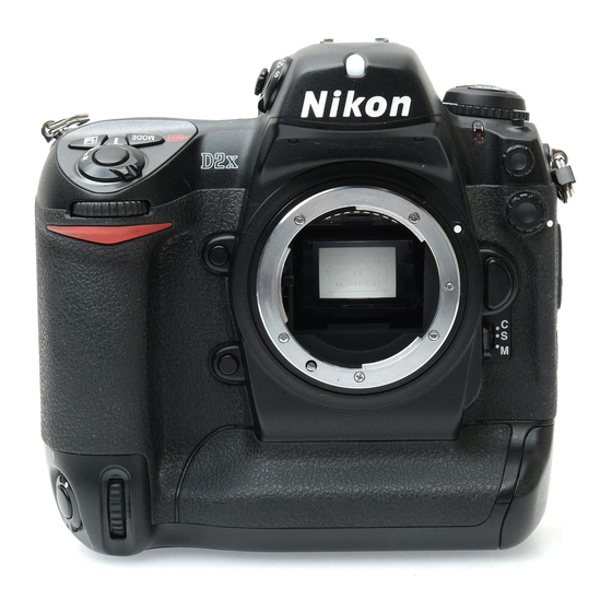
Nikon D2X Repair Manual
Hide thumbs
Also See for D2X:
- User manual (279 pages) ,
- Brochure (14 pages) ,
- Features & comparison chart (1 page)
Summary of Contents for Nikon D2X
- Page 1 VBA10501-R.3657.A 作成承認印 配布許可印 サービス 計画課 M VBA10501 REPAIR MANUAL Copyrigh c 2005 by Nikon Corporation. All Rights Reserved. 無断転載を禁ず !! Printed in Japan February 2005...
-
Page 2: Specifications
4288 × 2848 (L), 3216 × 2136 (M), 2144 × 1424 (S) High-speed crop on I3216 × 2136 (L), 2400 × 1600 (M), 1600 × 1064 (S) Lens mount Nikon F mount (with AF coupling and AF contacts) Compatible lenses* Type G or D AF Nikkor All functions supported... - Page 3 VBA10501-R.3657.A Autofocus TTL phase detection by Nikon Multi-CAM2000 autofocus module Detection range –1 – +19 EV (0 – +19 EV for two focus areas outside high-speed (ISO 100 at 20 °C / 68 °F) crop) AF-area mode Single-area AF, dynamic-area AF, group dynamic-AF, dynamic-area...
- Page 4 VBA10501-R.3657.A Flash Sync contact X-contact only; fl ash synchronization at up to 1⁄2 Flash contrrol TTL flash control by combined five-segment TTL multi sensor with single-component IC and 1,005-pixel AE sensor • SB-800, 600: i-TTL balanced fill-fl ash for digital SLR and standard i-TTL flash for digital SLR •...
-
Page 5: Operating Environment
• Nikon reserves the right to change the specifications of the hardware and software described in this manual at any time and without prior notice. Nikon will not be held liable for damages that may result from any mistakes that this manual may contain. -
Page 6: Precautions For Disassembly/(Re)Assembly
(Refer to Page A28 for the details when replaced.) Note 2: When "Seprating Front and Rear bodies", "Disassembling Image PCB", and "Disassembling Bayonet", be sure to perform "Reset of AF defocus compensation amount" by D2X adjustment software after reassembly. External rubber ・... - Page 7 VBA10501-R.3657.A I/F Block ① Take out 3 screws (#1589). ② Slacken A-part of I/F block. ③ Displace the I/F block downward a little, then unhook B-part. Remove the earth lug plate from the clearance between the back door and I/F PCB, being careful not to bend the plate.
- Page 8 VBA10501-R.3657.A Bottom Cover Unit 1. Remove Vertically position FPC ・ Remove the vertically position FPC from the connector. Vertically position FPC 2. Remove Bottom cover unit ・ Take out 3 screws (#1512) and 3 screws (#1517). ・ Remove the bottom cover unit from the camera body.
- Page 9 VBA10501-R.3657.A Back door unit 1. Remove Back door unit #1514×4 ・ Take out 4 screws (#1514) and detach the back door unit slowly. ・ Remove the TFT (Memory compression PCB Back door unit connection-FPC: #5041) from the connector. (ref. Fig.1 ) Connector Fig.1 #5041...
- Page 10 VBA10501-R.3657.A 3. TFT-PCB, Speaker, Microphone, other small parts #453 #425 #445 #427 � #1513×2 #B428 � TFT PCB #1522×2 #463 Speaker #437 #1560×2 #460 #467 #1508×3 #442 #456 Microphone #B439 #1531×2 TFT & Memory compression PCB connection-FPC ・ Remove the TFT & Memory compression PCB connection-FPC (#5041) from the connector. #5041 Connector - D5 ・...
- Page 11 VBA10501-R.3657.A Battery contacts unit 1. Remove wires ・ Remove the red and black wires that connect from the battery contacts. Black : Battery contact Red : Battery contact 2. Remove Battery contacts and Battery case upper unit ・ Remove the battery contacts connection-FPC from the connector. ・...


Need help?
Do you have a question about the D2X and is the answer not in the manual?
Questions and answers