
Related Manuals for Nikon D200


Summary of Contents for Nikon D200
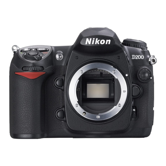
- Page 1 Advanced Digital Imagery System (ADIS) Nikon D200 Camera Kit -Checklist and Operations Manual- V3.0 2/28/2012 Florida Wing, Civil Air Patrol Charlotte County Composite Squadron, FL051...
- Page 2 GPS cable A – camera connector to D9 male connector GPS cable B – D9 female to GPS rectangular connector Garmin etrex GPS AMOD Data Logger Nikon quick charger with spare battery USB cable Spare AA batteries Memory Card (will likely already be installed in the camera) Camera to GPS cables (A&...
- Page 3 Page Button Power Button Battery Indicator 1.1 Nikon D200 Camera Pre-mission Initiation Verify that there is a memory card in the camera. Memory Card – kit includes, 1GB, 4GB and 8 GB cards Push this button to eject card...
- Page 4 Turn Camera on – See shutter switch on top right of camera On Off Switch +/- Button Display Battery Indicator Main Command Dial Look at the LCD display on the top-right of the camera. The battery symbol on the right side of the display should be fully grayed in indicating fully charge batteries.
- Page 5 Qual Button Cursor Control Button Nikon calls it the Multi-Selector Menu Button Enter Battery Button Reset Camera (push QUAL and +/- buttons simultaneously for 4 seconds) [Qual button is on the top left of the camera and has a green spot on it. +/- button is on the right top of the camera and has a green spot on it.
- Page 6 Spot Metering Selector Focus Selector Lock AF Area Mode Selector Look through viewfinder with lens cover on and shutter button depressed half way, Illuminated fields should show left to right: A solid circle inside of a rectangular box [spot metering] Low f3.5 P ISO 500 [898] [ISO set to 500 and 898 photos remaining] Remove lens cover and point camera at a bright outside scene –...
- Page 7 Delete Button Cursor Control Photo View Button Menu Button Take a test photo (adjust zoom as appropriate) Check the photo Press the push button to the upper left of the display screen [the one with the right arrow inside of an outlined box] to view the photo. It should look good.
- Page 8 Go to a place with an unobstructed view overhead. Take the etrex and camera with you. Turn on the etrex GPS. Push the Page Button several times until the SkyView page appears. Wait until the status message “Ready to Navigate” appears. Push the Page Button several times until the Main Menu screen appears.
- Page 9 Turn the camera off when you are done using it! [Turn Camera off – See shutter switch on top right of camera] 1.2 AMOD Data Tracker Install fresh batteries as follows: 1. Remove the back cover 2. Install three AA batteries as shown. The AMOD Tracker can use either rechargeable or non- rechargeable batteries.
- Page 10 It is recommended that the memory be cleared before each flight but only after the data logs for previous flights have been downloaded or considered no longer required. See the following for how to clear the memory. Clear the memory by holding the Mark button down for 5 seconds. All three status lights will illuminate sequentially.
- Page 11 2.0 Pre-Mission Planning 2.1 Identify Customer Requirements The flight crew needs the following information to assure successful acquisition of the aerial photographs required by the customer: Type of mission. The major types are: Spot Photography Route Photography Photographic Mapping Location ...
- Page 12 Camera Pointing Angle Camera pointing angle is the angle below the horizon. In a Cessna 182 or Cessna 172 with a photo window it is not possible to get a pointing angle much greater than 45 degrees. Smaller angles result in the photos being greater in extent perpendicular to the direction of flight and thus lower resolution at ground-level.
- Page 13 Resolution at the center of the photo will be 2.3 inches! Important – Most of the data in the table applies to both the Nikon D90 and Nikon D200 cameras. Resolution values are for the D90; numbers will be reduced slightly for the D200. For other cameras, the data may be way off as other cameras may have different image sensor dimensions.
- Page 14 For shallow camera pointing angles (see the 15 degree entry) the dimensions of each photograph for a 50 mm lens focal length become very large (approximately 2240 feet horizontal by 8900 feet perpendicular to the aircraft). Resolution is lower at the center of the camera axis;...
- Page 15 Determining Number of Photos For spot photography, take multiple photos as appropriate. More are better than less! For route photography and aerial mapping, one must determine the length of each leg. Using a map, determine each leg length in statute miles. Multiply the leg length in statute miles by 5280 feet per mile.
- Page 16 The Myakka Bridge in Charlotte County, FL was located by scrolling around the map. If an address is available for the target, it can be entered to find it on the map using the search feature. The computer cursor is pointed at the center of the bridge. The longitude and latitude of the pointer is listed to the right of the map.
- Page 17 The draw tool has been used surround the target with a square box with each side 1 mile from the center of the target. The cursor is then placed over each corner point, in turn, so that the Lat/long of each corner point can be determined for entry into...
- Page 18 3.0 Flying the Mission 3.1 Pre Engine Start Take the entire D200 kit with you to the aircraft. Get out the camera, the GPS and required cables. Put the rest of the kit in the baggage compartment and secure it. You...
- Page 19 Secure the camera strap to you or the airplane so as to assure the camera cannot be dropped out the window. Turn on the camera. After a minute or so, verify that the GPS is locked onto the satellite network. Point the camera out the photo window and take a picture. Verify that the photo is sharp, properly exposed and that the GPS data has been included in the photo.
- Page 20 Use the cursor (multi-selector) right button to move through the setup parameters. At each entry, use the cursor up or down button to change the value. A photo every 3 seconds is shown in the photo on the left. Continue to scroll right. Select the number of photos you want to shoot.
- Page 21 Use of a laptop while airborne If the mission requires the use of the Panasonic Toughbook laptop for photo download during the flight segment of the mission, use the camera to USB cable to make the connection. See the Panasonic Toughbook Computer ADIS Operations and Checklist Manual for details on computer usage.
- Page 22 4.0 Appendix 4.1 Spot Photography Circular Pattern Worksheet Distance off target Target Exit Entry Point Target description: ________________________________________________ Mission number: _______________ Sortie Number: _________________ Crew: PIC________________ OBS__________________ AP________________ 2 mile from target: altitude _______ft Entry point: Latitude ___________ Longitude ___________ Center of target: Latitude _______________...
- Page 23 4.2 Spot Photography Rectangular Pattern Worksheet Distance from target 2/28/2012...
Need help?
Do you have a question about the D200 and is the answer not in the manual?
Questions and answers