Table of Contents
Advertisement
Quick Links
Download this manual
See also:
Service Manual
Advertisement
Table of Contents

Related Manuals for Alto APM200


Summary of Contents for Alto APM200
- Page 1 User's Manual APM200 POWERED MIXER www.altoproaudio.com Version 1.0 JUNE 2007 English...
- Page 2 IMPORTANT SAFETY INSTRUCTION CAUTION WARNING To reduce the risk of electric shock RISK OF ELECTRIC SHOCK and fire, do not expose this equipment DO NOT OPEN to moisture or rain. TO REDUCE THE RISK OF ELECTRIC SHOCK PLEASE DO NOT REMOVE THE COVER OR Dispose of this product should THE BACK PANEL OF THIS EQUIPMENT.
-
Page 3: Table Of Contents
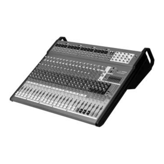
T eam of Audio Engineers and Musicians have developed with their great passion for music. Y our APM200 is a remarkable compact powered mixer that doesn' t find many equals in the market today. With 16 microphone and 2 stereo Line-level inputs... -
Page 5: Quick Start
3. QUICK START This is the fastest way to get something out from your APM200, if you have a keyboard and a microphone. a. Plug the microphone into Channel 1 MIC IN. b. Turn down AUX and LEVEL controls on the input channel. - Page 6 APM200 PHANTOM PHANTOM PHANTOM PHANTOM 20 CHANNEL 1500WATT+1000 WATT POWERED MIXER WITH 24-BIT MULTI-EFFECTS PROCESSOR +48V (CH 1-4) +48V (CH 5-8) +48V (CH 9-12) +48V (CH 13-16) MIC 1 MIC 2 MIC 3 MIC 4 MIC 5 MIC 6 MIC 7...
-
Page 7: Control Elements
Mono and Stereo Input Channels 1 The MONO MIC/LINE Channels Your APM200 is equipped with 16 low-noise microphone preamplifiers with optional phantom power, 45dB of Gain and over 115dB of S/N ratio. You can connect almost any type of microphone. Dynamic microphones do not need phantom power. - Page 8 4. CONTROL ELEMENTS 5 MONO IN GAIN This control is provided with 2 different indications: One is for the MIC and the other for LINE levels. When you use a microphone, you shall read the MIC ring (0~-45dB); when you use a line level instrument, you shall read the LINE ring (+15~-30dB).
- Page 9 4. CONTROL ELEMENTS 9 HI If you turn this control up, you will boost all the frequencies above 12 kHz (shelving filter). You will add transparency to vocals and guitar and also make cymbals crispier. Turn the control down to cut all frequencies above 12 kHz. In such way you can reduce sibilances of human voice or reduce the hiss of a Tape player.
- Page 10 4. CONTROL ELEMENTS 15 PAN/BAL Control Abbreviation of PANORAMA control for mono channels, or the stereo channels, always says, BALANCE control. Keep this control in center position, then the signal will be positioned in the middle of stage. 16 MUTE Switch Each channel is equipped with the MUTE switch.
-
Page 11: Footswitch Jack
4. CONTROL ELEMENTS AUX SEND AUX SEND P. AMP INPUT P. AMP INPUT P. AMP INPUT P. AMP INPUT ST OUT ST OUT LAMP LAMP (12V/0.5A) (12V/0.5A) AUX SEND AUX SEND DFX1 SEND DFX1 SEND ST SUB OUT ST SUB OUT MONO OUT MONO OUT ST SUB IN... - Page 12 4. CONTROL ELEMENTS 28 PHONES Jack This jack will be used to send the signal to a headphone or to a pair of powered studio monitors. 29 LAMP This lovable LAMP is very convenient for your operation, it is located in the top right corner of the front panel, and provides the 12V socket that can drive standard BNC-type lamp.
- Page 13 4. CONTROL ELEMENTS 38 LPF (MONO OUT) - LPF ON/OFF Switch This switch applies a low-pass filter to the signal that is output from the STEREO bus. - LPF Control You can adjust the frequency to the desired position by using a screwdriver to turn the control.
- Page 14 4. CONTROL ELEMENTS EQ OFF EQ OFF EQ ON EQ ON STEREO GRAPHIC EQ ST SUB GRAPHIC EQ 46 STEREO EQ Switch Engage this button to add the stereo graphic EQ into the main mix output circuit. It can be used to modify the frequency "contour" of a sound. If you release the button free, the stereo graphic EQ will be bypassed.
-
Page 15: Gain Control
4. CONTROL ELEMENTS 52 SIGNAL LED This LED will light up when the signal at the output is at least 100mV. 53 CLIP LED This LED will flash when distortion reaches a level of 0.5%, turn the relative GAIN control down so that the CLIP LED only flash occasionally. 54 PROTECTION LED It will light up when the unit is in Protection Mode SIG CLIP PROT... - Page 16 4. CONTROL ELEMENTS REAR PANEL CAUTION CAUTTION MODEL RISK OF ELECTRIC SHOCK LETHAL VOLTAGES MAY APPEAR AT OUTPUT DO NOT OPEN TERMINALS CLASS 1 WIRING IS REOUIRED WARNING: SHOCK HAZARD DO NOT OPEN SPEAKERS C-D SPEAKERS A-B AVIS: RISQUE DE CHOC ELECTRIQUE NE PAS OUVRIR SERIAL CAUTION: BRIDGE...
-
Page 17: Installation And Connection
5. INSTALLATION AND CONNECTION Ok, you have got to this point and you are now in the position to successfully operate your APM Series. However , we advise you to read carefully the following section to be the real master of your own powered mixer . Not paying attention enough to the input signal level, to the routing of the signal and the assignment of the signal will result in unwanted distortion, a corrupted signal or no sound at all. - Page 18 5. INSTALLATION AND CONNECTION Ring=Return Signal Sleeve Ring Strain Clamp Tip=Send Signal Sleeve=Ground/Screen Use for Insert Points 1/4" Stereo (TRS) Jack Plug 2=Hot(+) 2=Hot(+) 1=Ground/Screen 1=Ground/Screen 3=Cold(-) 3=Cold(-) Use for Balanced Mic Inputs Use for Main output (For unbalanced use, leave pin3 unconnected) (For unbalanced use, connect pin 1 to 3) 3-pin XLR Male Plug 3-pin XLR Line Socket...
- Page 19 5. INSTALLATION AND CONNECTION And now some tips how to use the AMPLIFIER MODE switch AMP A - B - MAIN L + MAIN R Mode Main Speaker SPEAKERS A-B BRIDGE MAIN L MAIN R SUB L SUB R BRIDGE AMP MODE MAX.
- Page 20 5. INSTALLATION AND CONNECTION - Bridge Mode Main Speaker SPEAKERS A-B MAIN L MAIN R BRIDGE SUB L SUB R BRIDGE AMP MODE MAX. OUTPUT 1500W/8 (A B,BRIDGE) 1 and 2 = 8 - 16 /SPEAKER MAX. OUTPUT 750W/4 (A,B) 1 or 2 = 4 - 8 /SPEAKER CLASS 2 WIRING WAY BE USED.
- Page 21 5. INSTALLATION AND CONNECTION - AUX1 + AUX2 Mode Stage Monitor SPEAKERS C-D BRIDGE MAIN L MAIN R AUX 1 AUX 2 BRIDGE AMP MODE MAX. OUTPUT 1000W/8 (A B,BRIDGE) 1 and 2 = 8 - 16 /SPEAKER MAX. OUTPUT 500W/4 (A,B) 1 or 2 = 4 - 8 /SPEAKER CLASS 2 WIRING WAY BE USED.
-
Page 22: Preset List
6. PRESET LIST Controllable Parameter Preset Description Parameter Variable range Decay time 0.8~1.1s VOCAL1 Simulate a room with small delay time. Pre-delay 0~79ms 0.8~2.5s Decay time VOCAL2 Simulate a small space with slight decay time 0~79ms Pre-delay Decay time 3.6~5.4s LARGE HALL Simulate a large acoustic space of the sound. -
Page 23: Block Diagram
7. BLOCK DIAGRAM... -
Page 24: Technical Specification
8. TECHNICAL SPECIFICATION Mono input channels Microphone input electronically balanced, discrete input configuration 10 Hz to 55 kHz, +/ 3 dB Frequency response Distortion (THD & N) 0.005% at +4 dBu, 1 kHz Gain 0 dB to 45 dB (MIC) SNR (Signal to Noise Ratio) 115 dB Line input... - Page 25 8. TECHNICAL SPECIFICATION Fuse 115 V : 12 A 230 V : 6.3 A Physical 145 mm Dimension (W Weight (Net) : 16.3 kg (35.9 lb) (Gross) : 21.8 kg (48.6 lb)
-
Page 26: Warranty
9. WARRANTY 1. WARRANTY REGISTRATION CARD To obtain Warranty Service, the buyer should first fill out and return the enclosed Warranty Registration Card within 10 days of the Purchase Date. All the information presented in this Warranty Registration Card gives the manufacturer a better understanding of the sales status, so as to purport a more effective and efficient after-sales warranty service. - Page 27 NO. 1, Lane 17, Sec. 2, Han Shi West Road, Taichung 40151, Taiwan http://www.altoproaudio.com Tel: 886-4-22313737 email: alto@altoproaudio.com Fax: 886-4-22346757 All rights reserved to ALTO. All features and content might be changed without prior notice. Any photocopy, translation, or reproduction of part of this manual without written permission is forbidden. Copyright...
Need help?
Do you have a question about the APM200 and is the answer not in the manual?
Questions and answers