
Subscribe to Our Youtube Channel
Related Manuals for Lennox L30 BF-2


Summary of Contents for Lennox L30 BF-2
-
Page 1: Installation And Operation
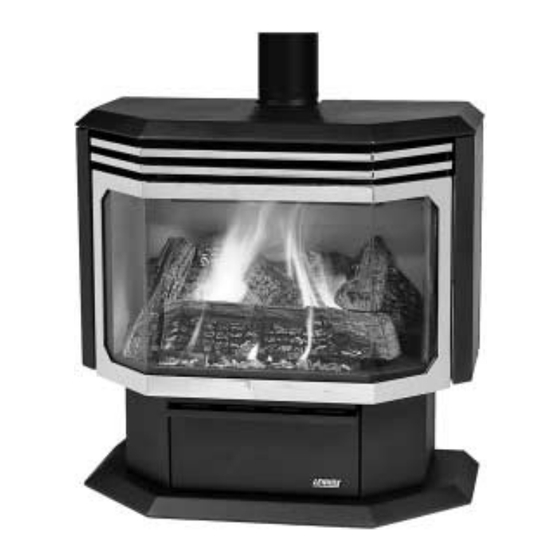
INSTALLATION AND OPERATION MANUAL FREESTANDING VENTED GAS FIREPLACE HEATER RETAIN THESE INSTRUCTIONS FOR FUTURE REFERENCE Shown with optional gold door and brickaded interior 189122-1050009... -
Page 2: Important Warnings
IMPORTANT WARNINGS / CAUTIONS CAUTION: Read this manual thoroughly before starting installation. For your safety, follow the installation, op- eration and maintenance instructions exactly without deviation. Failure to follow these instructions may result in a possible fire hazard and may void the warranty. If this appliance is not properly installed, a house fire may result. -
Page 3: Table Of Contents
The safety tests are conducted in accordance with American National Standards Institute (ANSI) requirements. The L30 BF-2 appliance is tested, certified, and listed by the CSA, AGA, CGA to ANSI Z21.88 - 1998 Vented Gas Fireplace Heaters and CSA 2.33 - 1998 Vented Gas Fireplace Heaters. -
Page 4: Planning Your Installation
PLANNING YOUR INSTALLATION LOCAL AND NATIONAL CODE REQUIREMENTS The installation of these appliances must conform with local codes or, in the absence of local codes, with the National Fuel Gas Code, (for USA) NFPA 54 / ANSI Z223.1-latest edition. Air Circulation Blower: The blower electrical power cord must be electrically grounded per local codes or per electrical codes: In USA, NEC, ANSI / NFPA 70-1987. - Page 5 PLANNING YOUR INSTALLATION QUESTIONS TO ASK THE LOCAL BUILDING OFFI- CIAL Correct installation is critical and imperative for reducing fire hazards and perilous conditions that can arise when gas appliances function improperly. The appliance must be installed per manufacturers’ instructions. Gas appliance equipment and installations must con- form to appropriate local codes and applicable state and federal requirements.
-
Page 6: Clearances To Combustible Materials
PLANNING YOUR INSTALLATION CLEARANCES TO COMBUSTIBLE MATERIALS These appliances can be installed in most residential room configurations, parallel to a rear or adjacent wall, or in an alcove that allows for the minimum clearances to combus- tible surfaces. Your local building inspector should review your plans prior to installation. -
Page 7: Installation
INSTALLATION See Pipe Manufacturers clearances for Pipe Clearances Venting Requirements EXAMPLES OF VENTING INSTALLATION APPLICATIONS Model: L30 BF-2 (B-Vent) Venting Requirements Approved for vertical termination only. Maximum Horizontal Pipe Runs for Given Vertical Pipe Run (in feet) Vertical run in feet 5’... -
Page 8: Gas Supply Hookup
INSTALLATION GAS SUPPLY HOOKUP If using pipe other than black iron pipe see NFPA 54-National Fire Protection Association / ANSI Z223.1-American National Standards Institute; and local code for specific requirements for the type of pipe used. Alternative gas piping systems such as CSST may be used subject to local code and proper sizing. -
Page 9: Door Operation
INSTALLATION DOOR OPERATION After setup of the logs and embers is complete, the glass door must be closed. The glass door is mounted on hinges at the left side of the firebox and is secured in the closed position by two draw latches mounted on the right side of the firebox. -
Page 10: Installing Log Set
INSTALLATION GAS APPLIANCE FINAL ASSEMBLY After the appliance has been properly installed and all gas connections have been made and tested, you can now install the log set. See Door Assembly on page 11 for door removal instructions. INSTALLING LOG SET: WARNING: If logs are not installed according to the directions in this manual, flame impingement and improper combustion could occur and result in ex-... -
Page 11: Installation Checklist
INSTALLATION INSTALLATION CHECK LIST Read and understand these instructions before using appliance. Go through this installation checklist: Ensure that the log set is properly installed. Use cau- tion when handling the logs. See page 10. Reinstall the door frame assembly. See Door Opera- tion on page 9. -
Page 12: Care And Operation
CARE AND OPERATION FOR YOUR SAFETY READ BEFORE LIGHTING WARNING: If you do not follow these instruc- tions exactly, a fire or explosion may result causing property damage, personal injury or loss of life. A. This appliance has a pilot which must be lit. When lighting the pilot, follow these instructions exactly. -
Page 13: Break-In Period
CARE AND OPERATION “BREAK-IN” PERIOD The finish on this appliance is a high temperature paint that requires time and temperature to completely cure. The curing process will take 2 or 3 burns (heat up and cool down periods). We recommend that you ventilate the house during the initial burns. -
Page 14: Propane Conversion
PROPANE CONVERSION PROPANE CONVERSION PROCEDURE (Only required if Propane gas is used) This appliance is designed to operate on natural gas, or propane (LP). It is factory set for use with natural gas and requires field conversion for use with propane. The use of other fuels or combination of fuels will degrade the performance of this system and may be dangerous. -
Page 15: Reference Information
PROPANE CONVERSION 7. High / Low Pressure Regulator Installation Proce- dure: a.Remove regulator cap and conversion screw (see following illustration). b.Install the new conversion screw (Red = Propane LP gas, Blue = Natural Gas). Ensure that the con- version screw is finger tight. Install the new regu- lator cap. -
Page 16: Maintenance
MAINTENANCE Always Turn Off Gas Control Valve Before Cleaning. Annual Maintenance Should Only Be Performed By A Qualified Service Technician: LOG SET Removing & Cleaning Logs - Carefully remove the logs (removing top logs, then lifting front log out, then rear log). -
Page 17: Maintenance
MAINTENANCE Always Turn Off Gas Control Valve Before Cleaning. Annual Maintenance Should Only Be Performed By A Qualified Service Technician: PERIODIC CHECK PILOT FLAMES Check the operation of the pilot and cycle the burner. Visually check the flame of the burner making sure the flames are steady;... -
Page 18: Wiring Diagrams
WIRING DIAGRAMS GAS CONTROL AND SAFETY SYSTEM WIRING DIAGRAM CAUTION: Label all wiring prior to disconnection when servicing controls. Wiring errors can cause improper and dan- gerous operation. Verify proper operation after servicing. The gas control wiring diagram shown here should be used by service technicians for guidance when troubleshooting problems with the pilot safety (millivolt) system or burner remote control system or when locating system components for repair / replacement. -
Page 19: Troubleshooting
TROUBLESHOOTING Qualified Technicians Only PROBLEM 1) Pilot will not light, and Piezo Igniter does not produce a heavy blue spark. 2) Pilot will not light, but Piezo Igniter pro- duces a heavy blue spark. 3) Pilot will not stay lit. 4) Pilot flame stays lit, but main burner will not light. -
Page 20: Replacement Parts
REPLACEMENT PARTS Item # Description Trim, Decorative Window Frame, Charcoal Burner Assembly Blower, Air Circulating Power Cord (blower) Rheostat w / Knob (speed control for blower) On / Off Switch, Burner Spill Switch Model L30-2 BF Item # Catalog # 52L04 17M63 17M61... -
Page 21: Optional Accessories
OPTIONAL ACCESSORIES Item # Description Door Kit, L30 BF-2, Gold Brickaded Interior Kit, L30 Deluxe Remote Control (Thermostatically controlled) Remote Control (Standard On / Off) Wall Thermostat Kit Touch-up Spray Paint Kit, Charcoal (3) Deluxe Remote Features Catalog # 14M09... -
Page 22: Specifications
SPECIFICATIONS: Model L30 BF-2 Approx. Sq. Ft. Heating Capacity 1500 sq. ft. Flue Size 4” - Top Vent Height Overall 29” Height to Flue Outlet 30 3/8” Width 29 7/8” Depth 16 1/8” Fuel Natural Gas (standard) (or) LP Gas (convertible). -
Page 23: Safety / Listing Label
SAFETY / LISTING LABEL: Model L30 BF-2 PAGE 23... -
Page 24: Ownership Records
OWNERSHIP RECORDS Dealer’s Name: Dealer’s Address: City: Serial Number: Notes: SERVICE AND MAINTENANCE LOG Service Service Service Date Technician Description State: Date of Purchase: PAGE 24 Zip Code: Date Installed:... - Page 25 1110 West Taft Avenue Orange, CA 92865...
Need help?
Do you have a question about the L30 BF-2 and is the answer not in the manual?
Questions and answers