Table of Contents
Advertisement
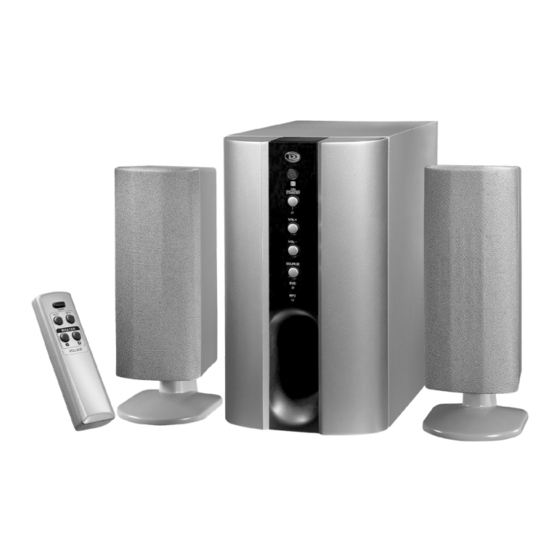
2.1 CHANNEL HOME THEATER SYSTEM
•
Compatible with MP3 & DVD Players, Computers and
Game Consoles
•
Dual Stereo Inputs for Easy Connections - Includes All
Cables
•
Active Subwoofer for Deep Bass
•
Tower Speakers are Wall Mountable with Removable
Pedestals (bases)
•
Remote Control and Batteries Included
•
Operates on 120V AC Power
IB-HT377-WM-E-050405.pmd
PLEASE READ CAREFULLY BEFORE USE
1
MODEL HT-377
IB-HT377-WM-E-050405
6/2/2005, 2:15 PM
Advertisement
Table of Contents

Related Manuals for Durabrand HT-377


Summary of Contents for Durabrand HT-377
- Page 1 • Active Subwoofer for Deep Bass • Tower Speakers are Wall Mountable with Removable Pedestals (bases) • Remote Control and Batteries Included • Operates on 120V AC Power PLEASE READ CAREFULLY BEFORE USE IB-HT377-WM-E-050405.pmd MODEL HT-377 IB-HT377-WM-E-050405 6/2/2005, 2:15 PM...
-
Page 2: Important Safety Instructions
SAFETY INSTRUCTIONS TO PREVENT FIRE OR SHOCK HAZARD, DO NOT USE THE PLUG WITH AN EXTENSION CO RD, RECEPTACLE O R O THER O UTLET UNLESS THE BLADES CAN BE FULLY INSERTED TO PREVENT BLADE EXPOSURE. TO PREVENT FIRE OR SHOCK HAZARD, DO NOT EXPOSE THIS APPLIANCE TO RAIN OR MOISTURE. -
Page 3: Safety Instructions
PRECAUTIONS ON SAFETY Should any solid object or liquid fall into the Home Theater System, unplug the player, and have it checked by qualified personnel before operating it any further. ON PLACEMENT OF YOUR HOME THEATER SYSTEM •... -
Page 4: Introduction
Trouble Shooting Guide at the end of this manual before you contact the Customer Service Department at 1-800-315-5885. Basic Features & Benefits of this Home Theater System: Includes audio inputs for DVD, CD player, VCR, computer, MP3, GAME/CAMERA etc. -
Page 5: Table Of Contents
TABLE OF CONTENTS • Getting Started Safety Instructions--------------------------------------------------------------------------------------------1,2 Introduction-----------------------------------------------------------------------------------------------------3 Location of Controls------------------------------------------------------------------------------------------5,6 Remote Control Operation----------------------------------------------------------------------------------6,7 Positioning Information --------------------------------------------------------------------------------------7 • Connections Speaker System Connections------------------------------------------------------------------------------8,9 TV Connections ----------------------------------------------------------------------------------------------10 TV + DVD Connections ------------------------------------------------------------------------------------11 TV + VCR Connections ------------------------------------------------------------------------------------12 TV + TV Game or Video Camera Connections ----------------------------------------------------------13 MP3/AUX Connections -------------------------------------------------------------------------------------14 •... -
Page 6: Location Of Controls
LOCATION OF CONTROLS FRONT PANEL STAN DBY SOURCE BACK OF MAIN SET (SUBWOOFER) IB-HT377-WM-E-050405.pmd 1. REMOTE SENSOR - Receives the signal from the REMOTE CONTROL (aim the R E M O T E control towards this sensor). 2. ON/STANDBY button - Press to switch the set to on or standby mode. -
Page 7: Location Of Controls
LOCATION OF CONTROLS REMOTE CONTROL ON/STANDBY MUTE S OUR CE REMOTE CONTROL OPERATION Battery Installation Remove the BATTERY COMPARTMENT DOOR of the REMOTE CONTROL and insert 2 size “AAA” alkaline batteries (included) according to the + and - markings inside the BATTERY COMPARTMENT of the REMOTE CONTROL unit, replace the door. -
Page 8: Positioning Information
Point the REMOTE CONTROL unit from less than 20 feet from the remote control sensor and within about 60 of the front of the HOME THEATER SYSTEM (not your TV set or DVD player). REMOT E SENSOR RANGE Distance within 20 feet... -
Page 9: Speaker System Connections
TV’s video input jack. WHITE NOTE: In order to have TV sound come through your home theater system, your TV must have AUDIO OUTPUT jacks. These jacks will always be in the rear of the TV (and not in the front). -
Page 10: Speaker System Connections
SPEAKER SYSTEM CONNECTIONS Tips for connecting the speaker wires Unwind and stretch out the speaker wires attached with each speakers, then push the set terminal tab on the back of the main set to insert each wire. Make sure the wire is fully inserted, but the insulation is not covering the inserted part of the speaker wires. -
Page 11: Tv Connections
Insert the stereo audio cables (included) into the DVD INPUT LEFT and RIGHT jacks on the back of your HOME THEATER SYSTEM, and into the corresponding AUDIO output jacks on your TV, this will allow your TV’s s ound to play through y our HOME THEATER SYSTEM. -
Page 12: Tv + Dvd Connections
Insert the stereo audio cables (included) into the DVD INPUT LEFT and RIGHT jacks on the back of your HOME THEATER SYSTEM, and into the corresponding AUDIO output jacks on your DVD player, this will allow your DVD’s sound to play through your HOME THEATER SYSTEM. -
Page 13: Tv + Vcr Connections
Insert the stereo audio cables (included) into the DVD INPUT LEFT and RIGHT jacks on the back of your HOME THEATER SYSTEM, and into the corresponding AUDIO output jacks on your VCR, this will allow your VCR’s sound to play through your HOME THEATER SYSTEM. -
Page 14: Tv + Tv Game Or Video Camera Connections
Insert the stereo audio cables (included) into the DVD INPUT LEFT and RIGHT jacks on the back of your HOME THEATER SYSTEM, and into the corresponding AUDIO output jacks on your TV Game or Video Camera, this will allow your TV Game or Video Camera’s sound to play through your HOME THEATER SYSTEM. -
Page 15: Mp3/Aux Connections
Insert the green 3.5 mm audio cable (included) into the MP3/AUX INPUT jack on the back of your HOME THEATER SYSTEM, and into the corresponding AUDIO output jack on your MP3, PC, CD player, or other device, this will enable you to hear your components system through your HOME THEATER SYSTEM. -
Page 16: Amplifier In Main Set
AMPLIFIER IN MAIN SET REMOTE CONTROL ON/STANDBY ON/S TA NDB Y button MU TE SOUR CE MUTE SOURCE button button VOLUME + VOLUME - button button General Make sure the POWER switch on the back of the main set is at “ON” position. Next press the ON/STANDBY button on the front of the main set or on the REMOTE CONTROL to turn the set on (or standby). -
Page 17: Blown Fuse
AMPLIFIER IN MAIN SET About fuse replacement NOTE: Before attempting to change the fuse, the system must be unplugged from the wall outlet. In the unusual event that nothing lights up and no sound, your fuse may have blown. To check for a blown fuse, follow the steps below. - Page 18 2.If the batteries are weak or dead, replace them with new ones (size “AAA”). 3.Point the remote control unit at a distance of less than 20 feet from the main unit of the HOME THEATER system. 4.Remove any obstacles between the remote control unit and remote control sensor.
-
Page 19: Ib-Ht377-Wm-E
LACQUER FINISH. For customer service of this Durabrand product Dial: 1-800-315-5885 (MONDAY-THURSDAY 8:00 AM - 5:00 PM, FRIDAY 8:00 AM - 1:00 PM EST) © 2005 LENOXX ELECTRONICS CORP. IB-HT377-WM-E-050405.pmd X 10 inches / 143 X 260 X 251 mm...
Need help?
Do you have a question about the HT-377 and is the answer not in the manual?
Questions and answers
I need the diagram of the electronic board and the power supply, to repair my home teather