Table of Contents
Advertisement
Specifications
lGeneral
Power Source:
Power consumption:
Dimensions (W×H×D):
Mass:
lAmplifier section
RMS Output Power: Dolby Digital Mode
lTotal RMS Dolby Digital
mode Power:
At 1kHz and total harmonic of 10%
lFront:
lCenter:
lSurround:
At 100Hz and total harmonic of 10%
lActive subwoofers:
FTC Output Power: Dolby Digital Mode:
lTotal FTC Dolby Digital mode Power:
At 120Hz-20kHz and total harmonic of 1%
lFront:
lCenter:
AC 120V, 60Hz
25 W
430×68×432 mm
(16-15/16"×2-11/16"×17")
4.1 kg (9.0Ibs)
800 W
70 W/ Channel (4Ω)
260 W/ Channel (4Ω)
70 W/ Channel (4Ω)
260 W/ Channel (4Ω)
470 W
45 W/ Channel (4Ω)
140 W/ Channel (4Ω)
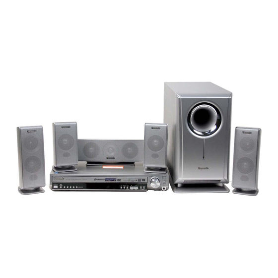
DVD Home Theater Sound System
SA-HT720P
SA-HT720PC
Colour
(S).......................Silver Type
lSurround:
At 45Hz-120Hz and total harmonic of 1%
lSubwoofer:
lFM tuner section
Frequency Range:
Sensitivity:
S/N 26dB
Antenna Terminal:
lAM tuner section
Frequency Range:
AM Sensitivity S/N 20dB at
999kHz:
Phone Jack:
Terminal:
lDisc section
Discs played [8 cm (3") or 12 cm (5")]:
(1) DVD-RAM (DVD-VR compatible, JPEG formatted discs)
(2) DVD-Audio
(3) DVD-Video
© 2004 Panasonic AVC Networks Singapore Pte.
Ltd. All rights reserved. Unauthorized copying and
distribution is a violation of law.
ORDER NO.MD0401026C1
A6
45 W/ Channel (4Ω)
150 W/ Channel (4Ω)
87.9-107.9MHz
(200kHz in step)
87.5-108.0MHz
(100kHz in step)
2.5µV (IHF)
2.2µV
75Ω (non balance)
520-1710kHz (10kHz in step)
560µV/m
Stereo 3.5mm (1/8") jack
Advertisement
Table of Contents

Subscribe to Our Youtube Channel
Related Manuals for Panasonic SA-HT720P


Summary of Contents for Panasonic SA-HT720P
-
Page 1: Specifications
(1) DVD-RAM (DVD-VR compatible, JPEG formatted discs) lFront: 45 W/ Channel (4Ω) (2) DVD-Audio lCenter: 140 W/ Channel (4Ω) (3) DVD-Video © 2004 Panasonic AVC Networks Singapore Pte. Ltd. All rights reserved. Unauthorized copying and distribution is a violation of law. - Page 2 SA-HT720P / SA-HT720PC (4) DVD-R (DVD-Video compatible) S-video output: 1 Vp-p (75 Ω) (5) CD-Audio (CD-DA) Y output level: NTSC; 0.286 Vp-p (75 Ω) (6) Video CD C output level: (7) SVCD (Conforming to IEC62107) Terminal S terminal (1 system)
-
Page 3: Table Of Contents
SA-HT720P / SA-HT720PC CONTENTS Page Page 1 Use of Active Subwoofer 12.1. Optical Pickup Breakdown Diagnosis 1.1. Checking Player when Active Subwoofer is not used 12.2. Service Mode Table 1 2 Safety Precautions 12.3. DVD Self Diagnostic Function-Error Code 2.1. GENERAL GUIDELINES 12.4. -
Page 4: Use Of Active Subwoofer
SA-HT720P / SA-HT720PC 1 Use of Active Subwoofer 1.1. Checking Player when Active Subwoofer is not used 1. This unit uses the active subwoofer to supply the power of the component, and the active subwoofer should be connected to the component to check operational conditions of the component. -
Page 5: Safety Precautions
SA-HT720P / SA-HT720PC 2 Safety Precautions 2.1. GENERAL GUIDELINES 1. When servicing, observe the original lead dress. If a short circuit is found, replace all parts which have been overheated or damaged by the short circuit. 2. After servicing, see to it that all the protective devices such as insulation barriers, insulation papers shields are properly installed. -
Page 6: Before Repair And Adjustment (Using Active Subwoofer)
SA-HT720P / SA-HT720PC Caution Be sure no power is applied to the chassis or circuit, and observe all other safety precautions. 8. Minimize bodily motions when handling unpackaged replacement ES devices. (Otherwise harmless motion such as the brushing together of your clothes fabric or the lifting of your foot from a carpeted floor can generate static electricity (ESD)sufficient to damage an ES device). -
Page 7: Precaution Of Laser Diode
SA-HT720P / SA-HT720PC 6 Precaution of Laser Diode CAUTION: This unit utilizes a class 1 laser. Invisible laser radiation is emitted from the optical pickup lens. Wavelength: 662nm(DVD)/785nm(VCD/CD). Maximum output radiation power from pickup: 100µW/VDE When the unit is turned on: 1. -
Page 8: General Description
SA-HT720P / SA-HT720PC 8 General Description 8.1. Operating instructions STOP/ FM MODE STANDBY/ON INDICATOR DISC EXCHANGE CD MODE/ TUNE MODE OPEN/CLOSE INPUT SELECTOR TUNING OPEN/CLOSE VOLUME DISC EXCHANGE DISC SKIP INPUT POWER SELECTOR C.S.M PROGRESSIVE CD MODE DOWN 5 DISC SELECTOR... -
Page 9: Disc Information
SA-HT720P / SA-HT720PC 8.2. Disc information... -
Page 10: Accessories
SA-HT720P / SA-HT720PC 9 Accessories 5 Speaker cables (4m×3, 10m×2) Remote control AC power supply cord AM loop antenna Antenna plug FM indoor antenna System cable Video Cable... -
Page 11: Handling Precautions For Optical Pickup Unit
SA-HT720P / SA-HT720PC 10 Handling Precautions for Optical Pickup Unit The laser diode in the optical pickup unit may brake down due to static electricity of clothes or human body. Use due caution to electrostatic breakdown when servicing and handling the laser diode. - Page 12 SA-HT720P / SA-HT720PC 10.3.2. Human body grounding 1. Use the anti-static wrist strap to discharge the static electricity form your body.
-
Page 13: Disassembly And Main Component Replacement Procedures
SA-HT720P / SA-HT720PC 11 Disassembly and Main Component Replacement Procedures “ATTENTION SERVICER” Some chassis components may have sharp edges. Be careful when disassembling and servicing. 1. This section describes procedures for checking the operation of the major printed circuit boards and replacing the main components. -
Page 14: Disassembling The Top Cabinet
SA-HT720P / SA-HT720PC 11.1. Disassembling the Top Cabinet Step 1 Remove 7 screws. Step 2 Remove the top cabinet in the direction of arrow. 11.2. Disassembling the Front Panel · Follow the (Step 1) - (Step 2) of Item 11.1. - Page 15 SA-HT720P / SA-HT720PC · Checking of Loading Motor P.C.B. and DVD Module P.C.B. Step 3 Pull out FFC CN6002. Step 5 Upset base assembly in vertical position. Step 4 Remove 4 screws. · Checking of Main P.C.B., Tray Motor and Sensor P.C.B.
-
Page 16: Removal Of The Tray Base Guide (L) And Tray Base Guide
SA-HT720P / SA-HT720PC 11.4. Removal of the Tray Base Guide (L) and Tray Base Guide · Follow the (Step 1) - (Step 2) of Item 11.1. · Follow the (Step 1) - (Step 4) of Item 11.2. · Follow the (Step 1) - (Step 5) of Item 11.3. -
Page 17: Removal Of The Tray Motor P.c.b. And Sensor
SA-HT720P / SA-HT720PC Step 3 Rotate close lock gear to direction of arrow, press claw (b) and pull out close lock gear. 11.8. Removal of the Tray Motor Step 2 Flip the base mecha unit in vertical position. P.C.B. and Sensor P.C.B. -
Page 18: Removal Of The Loading Motor
SA-HT720P / SA-HT720PC push drive gear shaft up. Step 2 Remove Drive Gear (A) and Drive Gear (B). Step 3 Release the 2 claws in the direction of arrow (1), and then push the pulley pin in the direction of arrow (2). -
Page 19: Removal Of The Cam Gear & Support Piece
SA-HT720P / SA-HT720PC 11.14. Removal of the Cam Gear & Support Piece · Follow the (Step 1) - (Step 5) of Item 11.3. Step 1 Rotate (A) in cam gear anti-clockwise. Step 2 Remove slide plate (L) & (R) and change lever as arrow shown. -
Page 20: Assembly Of Tray Base
SA-HT720P / SA-HT720PC 11.16. Assembly of Tray Base Step 1 Rotate cam gear anti-clockwise. Align at position (C) as marking on gear with arrow. Step 2 Make sure drive gear (A) at vertical position. Step 3 Push tray base to the direction of arrow shown. -
Page 21: Dvd-Optical Pick-Up Self-Diagnosis And Replacement Procedure
SA-HT720P / SA-HT720PC 12 DVD-Optical Pick-up Self-Diagnosis and Replacement Procedure 12.1. Optical Pickup Breakdown Diagnosis The optical pickup self-diagnosis function and tilt adjustment check function have been included in this unit. When repairing, use the following procedure for effective Self-diagnosis and tilt adjustment.Be sure to use the self-diagnosis functionbefore replacing the optical pickup when "NO DISC"... -
Page 22: Service Mode Table
SA-HT720P / SA-HT720PC 12.2. Service Mode Table 1 The service modes can be activated by pressing various button combination on the player and remote control unit. Player buttons Remote control unit buttons Application Note STOP Error code display (Refer to the item, “12.3. -
Page 23: Last Error Code Saved During No Play
SA-HT720P / SA-HT720PC Error Code Error Content Additional error explanation F890 Sending message when message is Sending message to AV task being sent to AV task F891 Message couldn’t be sent to AV task Begin sending message to AV task... -
Page 24: Service Mode Table
SA-HT720P / SA-HT720PC 12.5. Service mode table 2 Pressing various button combinations on the player and remote control unit can activate the service modes. - Page 25 SA-HT720P / SA-HT720PC...
-
Page 26: Sales Demonstration Lock Function
SA-HT720P / SA-HT720PC 12.6. Sales demonstration lock function This function prevents discs from being lost when the unit is used for sales demonstrations by disabling the disc eject function. "LOCKED" is displayed on the unit, and ordinary operation is disabled. -
Page 27: Self-Diagnosis Function
SA-HT720P / SA-HT720PC 13 Self-Diagnosis Function 13.2. Memorized Error Codes 13.2.1. Activating Self-Diagnosis Function 13.1. Automatic Displayed Error and Displaying Method Codes 1. Turn on the power. 13.1.1. Automatic Display Function 2. Select DVD/CD function. With no DVD/CD inserted in the... -
Page 28: Service Precautions
SA-HT720P / SA-HT720PC 14 Service Precautions 14.1. Recovery after the DVD player is repaired · When FROM or module P.C.B. is replaced, carry out the recovery processing to optimize the drive. Playback the recovery disk to process the recovery automatically. -
Page 29: Adjustment Procedure
SA-HT720P / SA-HT720PC 15 Adjustment Procedure 15.1. Service Tools and Equipment Application Name Number Tilt adjustment DVD test disc DVDT-S15 or DVDT-S01 Hex wrench Available on sales route. Others Grease RFKXPG641 Confirmation CD test disc PVCD-K06 or any other commercially... -
Page 30: Optical Adjustment
SA-HT720P / SA-HT720PC 15.4. Optical adjustment 15.4.1. Optical pickup tilt adjustment Measurement point Adjustment point Mode Disc Tangential adjustment screw T01 (inner periphery) play DVDT-S15 or DVDT-S01 Tilt adjustment screw T43 (outer periphery) play Measuring equipment Adjustment value None (Main unit display for servicing is used.) Adjust to the minimum jitter value. -
Page 31: Abbreviations
SA-HT720P / SA-HT720PC 16 Abbreviations INITIAL/LOGO ABBREVIATIONS INITIAL/LOGO ABBREVIATIONS A0~UP ADDRESS ERROR TORQUE CONTROL ACLK AUDIO CLOCK ERROR TORQUE CONTROL AD0~UP ADDRESS BUS REFERENCE ADATA AUDIO PES PACKET DATA ENCSEL ENCODER SELECT ADDRESS LATCH ENABLE ETMCLK EXTERNAL M CLOCK (81MHz/40.5MHz) - Page 32 SA-HT720P / SA-HT720PC INITIAL/LOGO ABBREVIATIONS INITIAL/LOGO ABBREVIATIONS READ ENABLE VBLANK V BLANKING RFENV RF ENVELOPE COLLECTOR POWER SUPPLY RF PHASE DIFFERENCE OUTPUT VOLTAGE (CD-ROM) REGISTER SELECT VCDCONT VIDEO CD CONTROL (TRACKING RSEL RF POLARITY SELECT BALANCE) RESET DRAIN POWER SUPPLY VOLTAGE...
-
Page 33: Voltage Chart
SA-HT720P / SA-HT720PC 17 Voltage Chart 17.1. DVD Module P.C.B. IC8001 Ref No. MODE CD PLAY STANDBY IC8001 Ref No. MODE CD PLAY STANDBY IC8001 Ref No. MODE CD PLAY STANDBY IC8001 Ref No. MODE CD PLAY STANDBY Ref No. - Page 34 SA-HT720P / SA-HT720PC IC8451 Ref No. MODE CD PLAY STANDBY IC8451 Ref No. MODE CD PLAY STANDBY Ref No. IC8601 MODE CD PLAY STANDBY IC8605 Ref No. MODE CD PLAY STANDBY IC8611 Ref No. MODE CD PLAY STANDBY IC8651 Ref No.
-
Page 35: Main P.c.b
SA-HT720P / SA-HT720PC 17.2. Main P.C.B. IC2000 Ref No. MODE CD PLAY STANDBY IC2001 Ref No. MODE CD PLAY 13.4 STANDBY 13.5 IC2002 Ref No. MODE CD PLAY 13.5 STANDBY 13.7 IC2004 Ref No. MODE CD PLAY STANDBY Ref No. -
Page 36: Fl P.c.b
SA-HT720P / SA-HT720PC IC2021 Ref No. MODE CD PLAY -6.7 STANDBY -6.7 IC2022 Ref No. MODE CD PLAY -6.7 STANDBY -6.7 Q2000 Q2001 Q2002 Q2004 Q2011 Ref No. MODE CD PLAY 13.5 -3.0 13.5 STANDBY 13.8 -3.0 13.7 Q2012 Q2013... -
Page 37: Sensor P.c.b
SA-HT720P / SA-HT720PC 17.6. Sensor P.C.B. Q9103 Ref No. MODE CD PLAY STANDBY... -
Page 38: Schematic Diagram Notes
SA-HT720P / SA-HT720PC 18 Schematic Diagram Notes · This schematic diagram may be modified at any time Caution! with the development of new technology. IC and LSI are sensitive to static electricity. Notes: Secondary trouble can be prevented by taking care during... -
Page 39: Block Diagram
SA-HT720P / SA-HT720PC 19 Block Diagram IC8001 IC8251 MN2DS0003APH C0GBG0000044 OPTICAL PICK UP UNIT TRACKING COIL/FOCUS COIL/TRAVERSE MOTOR DRIVE PHOTO DETECTOR VIN1 VOL4+ VIN2 VIN3 HEAD VIN4 LEVEL VOL4- SHIFT VIN8 BIAS1 VIN7 VIN6 TRV DRV VIN1 VIN5 PWM1 VOL3+... - Page 40 SA-HT720P / SA-HT720PC IC8051 IC8001 IC8451 C3ABPG000063 MN2DS0003APH C0FBBK000036 64M SDRAM AUDIO DAC OUTPUT AMP AND V OUT7 DVD MIX L LOW-PASS FILTER BCK IN SRCK LRC IN MEMORY MEMORY LRCK ADDRESS ADDRESS D IN1 V OUT8 DVD MIX R...
- Page 41 SA-HT720P / SA-HT720PC TUNER PACK AM ANT FM ANT IC2006 MIXER C9ZB00000431 IF AMP VIDEO DRIVE COIL COIL RF AMP BUFFER BIAS 150K Y/PY/G CY IN 13.5MHz JK2001 CY OUT Y(RED) (FM) BIAS CY SAG 150K CB/PB/B CB IN 13.5MHz...
- Page 42 SA-HT720P / SA-HT720PC IC2013 C0AABB000125 HEADPHONES AMP IC2011 C1BB00000845 (6)2 1(7) APS(INPUT SELECT/DIGITAL SOUND PROCESSOR/ELECTRONIC VOLUME/TONE) (5)3 Q2102 Q2201 TMF L TMF RB TMF LB MUTING (TMFR) (TMF RA) (TMF LA) MUTING CONTROL (L OUT2) L OUT1 JK2001 (60)59 (OUT FR)
- Page 43 SA-HT720P / SA-HT720PC SIGNAL LINES : MAIN SIGNAL LINE : AM SIGNAL LINE : DVD AUDIO SIGNAL LINE : FM SIGNAL LINE : AM OSC SIGNAL LINE : DVD VIDEO SIGNAL LINE : FM OSC SIGNAL LINE : FM /AM SIGNAL LINE : CD-DA (AUDIO /VIDEO) SIGNAL LINE ( ) Indicates the Pin No.
- Page 44 SA-HT720P / SA-HT720PC...
-
Page 45: Schematic Diagram
SA-HT720P / SA-HT720PC 20 Schematic Diagram SCHEMATIC DIAGRAM-1 DVD MODULE(IN/OUT) CIRCUIT : +B SIGNAL LINE : CD-DA SIGNAL LINE : MAIN SIGNAL LINE : DVD(VIDEO) SIGNAL LINE : DVD(AUDIO) SIGNAL LINE IC8271 Spindle Motor Drive SPINDLE MOTOR ASSY IC8251 Tracking Coil/Focus Coil... - Page 46 SA-HT720P / SA-HT720PC SCHEMATIC DIAGRAM-2 DVD MODULE(DV2) CIRCUIT : +B SIGNAL LINE : CD-DA SIGNAL LINE : DVD(VIDEO) SIGNAL LINE : DVD(AUDIO) SIGNAL LINE IC8051 64M SDRAM FLASH ROM WRITING IC8651 RFKFMH81T160 IC8611 C3EBGZ000001 EEPROM IC IC8001 DV2-1 LSI IC8601...
- Page 47 SA-HT720P / SA-HT720PC SCHEMATIC DIAGRAM-3 : +B SIGNAL LINE : MAIN SIGNAL LINE : DVD(VIDEO) SIGNAL LINE : FM/AM SIGNAL LINE MAIN CIRCUIT IC2007 C0GAG0000007 Motor Drive(Tray) CN2010 TRV REV TRV FWD TRV- 11 C+9V TRV+ C2023 C2024 L2003 R2093...
- Page 48 SA-HT720P / SA-HT720PC SCHEMATIC DIAGRAM-4 MAIN CIRCUIT : +B SIGNAL LINE : -B SIGNAL LINE : MAIN SIGNAL LINE : FM/AM SIGNAL LINE C2819 16V47 R2163 R2263 R2505 C2503 C2506 C2818 16V47 0.033 0.01 C2810 220P R2508 C2163 C2263 C2504 R2504 1.8K...
- Page 49 SA-HT720P / SA-HT720PC SCHEMATIC DIAGRAM-5 MAIN CIRCUIT 3 : +B SIGNAL LINE : -B SIGNAL LINE : DVD(VIDEO) SIGNAL LINE R2058 R2056 R2620 R2308 R2166 R2266 R2897 R2057 1.8K 1.8K 1.8K 1.8K C2000 STBY LED Q2600 Q2103 Q2105 Q2201 Q2029...
- Page 50 SA-HT720P / SA-HT720PC SCHEMATIC DIAGRAM-6 MAIN CIRCUIT : +B SIGNAL LINE : -B SIGNAL LINE : MAIN SIGNAL LINE IC2004 IC2000 IC2002 IC2001 C0CBADG00023 C0CBADG00023 C0DBAZG00033 C0DBAZG00033 R2974 Regulator Regulator DC-DC Converter DC-DC Converter DISC2 R2975 DISC1 C2053 L2019 G0A101G00022...
- Page 51 SA-HT720P / SA-HT720PC SCHEMATIC DIAGRAM-7 : +B SIGNAL LINE : MAIN SIGNAL LINE FL CIRCUIT HEADPHONE CIRCUIT FL6901 A2BD00000082 CN6901 JK6901 R6940 0 K2HC103A0023 L6101 R6939 0 J0JBC0000019 FLDA C6903 C6905 R6935 R6936 C6101 50V22 50V22 L6201 0.047 FLCLK J0JBC0000019...
- Page 52 SA-HT720P / SA-HT720PC SCHEMATIC DIAGRAM-8 TRAY MOTOR CIRCUIT SENSOR CIRCUIT M9101 Q9103 (TRAY MOTOR) B3NAB0000027 FC9101 PHOTO INTERRUPTOR TRAY MOTOR- TRAY MOTOR- TRAY MOTOR- TRAY MOTOR+ TRAY MOTOR+ TRAY MOTOR+ PHOTO_DRV/A PHOTO_DR V/A DGND DGND DGND Q9102 PHOTO_DRV/B MAIN PULSE_SENSE...
-
Page 53: Printed Circuit Board Diagram
SA-HT720P / SA-HT720PC 21 Printed Circuit Board Diagram A A A A A A A A DVD MODULE P.C.B. (REP3654G) (SIDE:A) DVD MODULE P.C.B. (REP3654G) (SIDE:B) CP8252 C8254 TP8514 C8255 C8503 LB8502 CP8251 TP8515 TP8517 TP8500 TC8501 TC8502 R8501 TP8511... - Page 54 SA-HT720P / SA-HT720PC A A A A MAIN P.C.B. (REPX0419A) R2884 R2891 C2042 R2885 C2803 C2804 MAIN P.C.B. (REPX0419A) C2802 C2801 C2044 L2022 R2878 R2886 R2879 C2808 R2883 L2025 R2882 R2889 R2880 C2040 C2805 R2881 R2887 C2807 C2608 R2888 IC2007...
- Page 55 SA-HT720P / SA-HT720PC A A A A FL P.C.B. (REPX0415A) W2011 D6903 D6902 D6901 W2018 D6900 W2006 D6905 W2002 D6904 W2021 W2001 W2020 W2005 L6903 W2003 R6944 R6945 R6943 R6942 R6941 W2000 R6926 R6925 R6924 R6923 R6922 IC6902 W2013 R6909...
- Page 56 SA-HT720P / SA-HT720PC A A A A TRAY MOTOR P.C.B. LOADING MOTOR P.C.B. (REP3466A) (REP3465A) M9101 Q9102 M9001 SENSOR P.C.B. (REPX3466A) Q9103 CN9102...
-
Page 57: Wiring Connection Diagram
SA-HT720P / SA-HT720PC 22 Wiring Connection Diagram VOLUME OPTICAL PICKUP CN6901 VR6800 FL P.C.B. JK6801 HEADPHONE P.C.B. CN6801 HEADPHONE FP8501 JACK DVD MODULE P.C.B. (SIDE:A) CN2009 CN2008 M9101 SENSOR P.C.B. TRAY MOTOR CN9102 P.C.B. CN2010 MAIN P.C.B. SSPINDLE MOTOR ASS'Y... - Page 58 SA-HT720P / SA-HT720PC...
-
Page 59: Illustration Of Ic , Transistors And Diodes
SA-HT720P / SA-HT720PC 23 Illustration of IC’s, Transistors and Diodes C0ABCB000052 (14p) C0FBBK000036 (48p) C3FBMD000134 C0AABB000125 C0CBCBD00018 (8p) C0HBB0000040 (48p) C0JBAR000292 (16p) C1BB00000845 (80p) C3ABPG000063 (54p) C2CBHG000137 (100p) No.1 C9ZB00000431 (34p) MN2DS0003APH (256p) No.1 C3EBDG000052 C0GAG0000007 C0GBF0000004 C0CBADG00023 C3EBGZ000001 C0ABBB000118... -
Page 60: Terminal Function Of Ics
SA-HT720P / SA-HT720PC 24 Terminal Function of ICs 24.1. IC2018 (C2CBHG000137): Terminal Function Name Operation CPU Not used, open Analog surround signal output Terminal Function Not used, open Name PARTY Analog surround signal output LOAD UP/DOWN switch signal input Not used, open... -
Page 61: Parts Location And Replacement Parts List
SA-HT720P / SA-HT720PC 25 Parts Location and Replacement Parts List Notes: *Important safety notice: Components identified by mark have special characteristics important for safety. Furthermore, special parts which have purposes of fire-retardant (resistors), high-quality sound (capacitors), low-noise (resistors), etc. are used. -
Page 62: Loading Mechanism, Traverse Unit & Cabinet
SA-HT720P / SA-HT720PC 25.1. Loading Mechanism, Traverse Unit & Cabinet 25.1.1. Loading Mechanism, Traverse Unit & Cabinet Parts Location... - Page 63 SA-HT720P / SA-HT720PC...
- Page 64 SA-HT720P / SA-HT720PC...
- Page 65 SA-HT720P / SA-HT720PC 25.1.2. Traverse and Cabinet Parts List Ref. Part No. Part Name & Description Remarks RMR1447-X MAGNET HOLDER Ref. Part No. Part Name & Description Remarks RMR1596-K MIDDLE CHASSIS RMR1507-X SUPPORT PIECE RMS0789 FIXED PIN CABINET AND CHASSIS...
-
Page 66: Component Parts List
SA-HT720P / SA-HT720PC 25.2. Component Parts List Ref. Part No. Part Name & Description Remarks Ref. Part No. Part Name & Description Remarks Q2027 B1GDCFGA0014 TRANSISTOR PRINTED CIRCUIT BOARD Q2028 B1GBCFJN0021 TRANSISTOR Q2029 B1GBCFJN0021 TRANSISTOR REP3454G DVD MODULE (1) P.C.B. - Page 67 SA-HT720P / SA-HT720PC Ref. Part No. Part Name & Description Remarks Ref. Part No. Part Name & Description Remarks D2035 B0ACCK000005 DIODE S6904 EVQ21405R TACT SWITCH SW DISC3 D2036 B0ACCK000005 DIODE S6905 EVQ21405R TACT SWITCH SW DISC4 D2039 B0ADCJ000020 DIODE...
- Page 68 SA-HT720P / SA-HT720PC Ref. Part No. Part Name & Description Remarks Ref. Part No. Part Name & Description Remarks FL8101 F1H0J1050022 1 6.3V W2058 ERJ6GEY0R00V 0 1/10W FL8102 F1H0J1050022 1 6.3V W2059 ERJ6GEY0R00V 0 1/10W FL8103 F1H0J1050022 1 6.3V W2060...
- Page 69 SA-HT720P / SA-HT720PC Ref. Part No. Part Name & Description Remarks Ref. Part No. Part Name & Description Remarks R2039 ERJ3GEYJ221V 220 1/16W R2124 ERJ3GEYJ223V 22K 1/16W R2040 ERJ3GEYJ221V 220 1/16W R2125 ERJ3GEYJ222V 2.2K 1/16W R2041 ERJ3GEYJ221V 220 1/16W R2126...
- Page 70 SA-HT720P / SA-HT720PC Ref. Part No. Part Name & Description Remarks Ref. Part No. Part Name & Description Remarks R2245 ERJ3GEYJ682V 6.8K 1/16W R2512 ERJ3GEYJ103V 10K 1/16W R2246 D0GB333JA002 33K 1/16W R2513 D0GB273JA002 27K 1/16W R2247 ERJ3GEYJ220V 22 1/16W R2514...
- Page 71 SA-HT720P / SA-HT720PC Ref. Part No. Part Name & Description Remarks Ref. Part No. Part Name & Description Remarks R2857 ERJ3GEYJ153V 15K 1/16W R6915 ERJ3GEYJ102V 1K 1/16W R2858 D0GB393JA002 39K 1/16W R6916 ERJ3GEYJ680V 68 1/16W R2859 ERJ3GEYJ472V 4.7K 1/16W R6917...
- Page 72 SA-HT720P / SA-HT720PC Ref. Part No. Part Name & Description Remarks Ref. Part No. Part Name & Description Remarks R8562 ERJ3GEYJ331V 330 1/16W C2040 ECA0JM102B 1000 6.3V R8563 ERJ3GEYJ102V 1K 1/16W C2041 ECEA0JKA101B 100 6.3V R8564 D0GB100JA002 10 1/16W C2042 ECA0JM102B 1000 6.3V...
- Page 73 SA-HT720P / SA-HT720PC Ref. Part No. Part Name & Description Remarks Ref. Part No. Part Name & Description Remarks C2137 ECUV1H104KBV 0.1 50V C2262 ECJ1VB1C333K 0.033 16V C2138 ECJ1VC1H221J 220P 50V C2263 ECEA1HKA3R3B 3.3 50V C2139 ECJ1VC1H101K 100P 50V C2264...
- Page 74 SA-HT720P / SA-HT720PC Ref. Part No. Part Name & Description Remarks Ref. Part No. Part Name & Description Remarks C2826 ECJ1VB1E103K 0.01 25V C8213 ECJ1ZF1C104Z 0.1 16V C2827 ECJ1VB1E103K 0.01 25V C8214 ECJ1ZF1C104Z 0.1 16V C2828 ECUV1C104KBV 0.1 16V C8215...
-
Page 75: Packing Materials & Accessories Parts List
SA-HT720P / SA-HT720PC Ref. Part No. Part Name & Description Remarks Ref. Part No. Part Name & Description Remarks C8601 ECJ0EF1C104Z 0.1 16V C8622 ECJ1VC1H050D 5P 50V C8605 ECJ0EF1C104Z 0.1 16V C8651 ECJ1ZF1C104Z 0.1 16V C8606 ECJ1VB1A224K 0.22 10V C8652 ECJ1ZF1C104Z 0.1 16V...
Need help?
Do you have a question about the SA-HT720P and is the answer not in the manual?
Questions and answers