Table of Contents
Advertisement
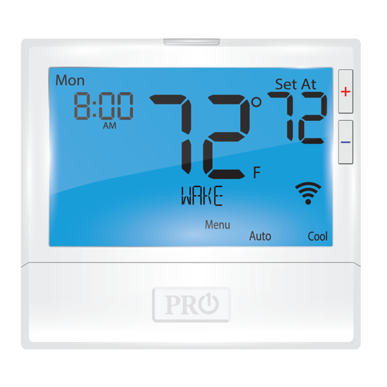
T855
i
Thermostat Applications Guide
Description
Gas or Oil Heat
Electric Furnace
Heat Pump (No Aux. or Emergency Heat)
Heat Pump (with Aux. or Emergency Heat)
Multi-stage Systems
Heat Only Systems
Cool Only Systems
Millivolt
Table of Contents
Patents and Trademarks pending.
Copyright © 2013. All rights reserved.
Power Type
Hardwire (24 VAC Common Wire)
Yes
Yes
Yes
Yes
Yes
Yes
Yes
No
A trained, experienced technician
must install this product.
Page
Carefully read these instructions. You
could damage this product or cause a
hazardous condition if you fail to follow
2
these instructions.
3
4
5-6
7-11
12-15
16
INSTALLATION MANUAL
MENU AUTO HEAT
Una versión en español de este
manual se puede descargar en la
página web de la compañía.
1
Rev. 1429
Advertisement
Table of Contents

Subscribe to Our Youtube Channel
Related Manuals for Pro1 IAQ T855i


Summary of Contents for Pro1 IAQ T855i
-
Page 1: Table Of Contents
INSTALLATION MANUAL T855 MENU AUTO HEAT Power Type Thermostat Applications Guide Hardwire (24 VAC Common Wire) Description Gas or Oil Heat Electric Furnace Heat Pump (No Aux. or Emergency Heat) Heat Pump (with Aux. or Emergency Heat) Multi-stage Systems Heat Only Systems Cool Only Systems Millivolt A trained, experienced technician... -
Page 2: Installation Tips
INSTALLATION TIPS Wall Locations Getting to know your thermostat The thermostat should be installed approximately 4 to 5 feet above the oor. Select an area with average temperature and good air circulation. Displays the user Hold is displayed when Indicates the thermostat program is selectable setpoint current room... -
Page 3: Themostat Quick Reference
THERMOSTAT QUICK REFERENCE Getting to know your thermostat LCD Display 5:23 Glow in the Dark Light Button Temperature Set Point Buttons User Program Buttons Fan Button System Button Menu Auto Button Access Door MENU AUTO HEAT Indicates the current room Days of the temperature. -
Page 4: Subbase Installation
SUBBASE INSTALLATION Caution Caution: Mercury Notice: Electrical Hazard All of our thermostats are Failure to disconnect the mercury free. However, if the power before beginning to product you are replacing install this product can cause contains mercury, dispose of it electric shock or equipment properly. -
Page 5: Wiring
WIRING Power supply Factory-installed jumper. Remove only when installing on 2-transformer systems Use either O or B terminals for changeover valve A 24 VAC common connection is required with this thermostat. Typical 2H/2C system: 1 transformer Typical 2H/2C system: 2 transformer REMOVE JUMPER L1 (HOT) L1 (HOT) - Page 6 WIRING Replacement Thermostat Wiring Warning All components of the control If you are replacing a thermostat, make note system and the thermostat of the terminal connections on the thermo- installation must conform to stat that is being replaced. In some cases the Class II circuits per the NEC wiring connections will not be color-coded.
-
Page 7: Technician Setup Menu
TECHNICIAN SETUP MENU Technician Setup Menu - System Operation Con gure the installer options as desired, using the table below. This thermostat has a technician setup menu for easy installer con guration. To setup the Use the keys to thermostat for your particular application: change settings and the PREV or NEXT key to move from one step to another. - Page 8 TECHNICIAN SETUP MENU Tech Setup Steps (Continued from the previous page) Heating Cooling ºF or ºC 12 or 24 Morning Program Temperature Temperature Time Periods Hour Clock Operation Recovery Options Setpoint Limit Setpoint Limit This feature allows This feature allows This feature allows You can select You can con gure...
- Page 9 TECHNICIAN SETUP MENU Tech Setup Steps (Continued from the previous page) Display Pre Occupancy Contractor System Gas Auxiliary Stages of Heat Heat Pump Beep Light Call Number for Heat Pump and Cool When turned on Allows you to put When any key is This option will turn Set system switch for You can configure this...
- Page 10 TECHNICIAN SETUP MENU Tech Setup Steps (Continued from the previous page) UV Lamp Satisfy Humidity Pad IAQ Cell Cooling Fan Staging Delay IAQ Mode Cycle IAQ Mode Minutes Reminder Setpoint Reminder Reminder Delay This allows you to This feature allows This feature allows a Will remind the user Will remind the user...
-
Page 11: Advanced Settings
TECHNICIAN SETUP MENU - Wi-Fi Technician Setup Menu - Wi-Fi These steps/options are only used for trouble shooting, re-setting or restoring to default the Wi-Fi settings of the thermostat. They are not needed for installation or initial setup. At this point press and hold TECH to enter Press MENU button. -
Page 12: Programming
PROGRAMMING THE THERMOSTAT Set Time Follow the steps below to set the day of the week and current time: Press MENU Press TIME Day of the week will be flashing. Use the key to select the current day of the week. Press NEXT The current hour is flashing. - Page 13 PROGRAMMING THE THERMOSTAT Occupied Unoccupied Occupied Unoccupied Occupied Unoccupied...
- Page 15 Sunday time...
-
Page 16: Features And Speci Cations
FEATURES & SPECIFICATIONS Filter Change and other Reminders Temporary and Permanent Hold Feature If your installing contractor has configured Temporary hold: The thermostat will display the thermostat to remind you when the air HOLD and RUN on the bottom of filter needs changed, you will see FILT in the your screen when you press the display when your air filter needs changed.
Need help?
Do you have a question about the T855i and is the answer not in the manual?
Questions and answers