
Related Manuals for Funkwerk ATR833 - OLED


Summary of Contents for Funkwerk ATR833 - OLED
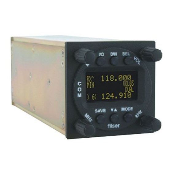
- Page 1 ATR833 - OLED VHF Communication Transceiver P/N 833-(1xx)-(1xx) Operation and Installation (Document-No. 01.1402.010.71e)
- Page 2 ATR833 / P/N 833-(1xx)-(1xx) Operation and Installation Change History Revision Date Description of Change 1.00 11.08.2009 FAV – First Release 1.01 15.10.2009 Changed order of Basic Settings (SW5.6) List of the Service Bulletins (SB) Services bulletins are to be inserted in the manual and to be put down in this table.
-
Page 3: Table Of Contents
ATR833 / P/N 833-(1xx)-(1xx) Operation and Installation Contents General ....................5 Symbols ...................5 Abbreviations ................5 Customer Support ..............6 Features ...................6 Operation ...................7 Controls..................7 ON/OFF..................9 Display ..................9 Basic Settings ................11 2.4.1 VOL – Volume .............12 2.4.2 SQ – Squelch ..............12 2.4.3 VOX – Voice Detection (Intercom Function)....13 2.4.4 DIM –... - Page 4 ATR833 / P/N 833-(1xx)-(1xx) Operation and Installation 2.9.2 Transfer of the user-defined frequency list ....26 2.10 Remote Control Panel............27 Installation ..................28 Advices and Tips..............28 Telecommunication Data ............28 Scope of delivery..............28 Unpacking and Inspecting the Equipment......29 Mounting ................29 Equipment Connections ............30 3.6.1 Microphone-Connection ..........30 3.6.2 Headset-Connection............30 3.6.3 Audio-Input ..............31...
-
Page 5: General
ATR833 / P/N 833-(1xx)-(1xx) Operation and Installation 1 GENERAL This manual contains information about the physical, mechanical and electrical characteristics as well as information about installation and operation of the aeronautical radio device VHF ATR833. 1.1 Symbols Advices whose non-observance can cause radiation damage to the human body or ignition of combustible materials. -
Page 6: Customer Support
Service-Area within the Funkwerk Avionics web portal www.funkwerk- avionics.com. Any suggestions for improvement of our manuals are welcome. Contact: service@funkwerk-avionics.com. Informations on software updates are available at Funkwerk Avionics. 1.4 Features • VHF communication transceiver for aircraft installation • frequency range118,000 to 136,975 MHz •... -
Page 7: Operation
ATR833 / P/N 833-(1xx)-(1xx) Operation and Installation 2 OPERATION 2.1 Controls De- / Selection key for Activate adjusting VOL, dual mode VOX, SQ, etc. … ON/OFF Select from user- Adjusting of defined frequency volume and VOX memory threshold etc. … Rotary knob Rotary knob Rotary knob... - Page 8 ATR833 / P/N 833-(1xx)-(1xx) Operation and Installation Switch On press button for approx. 0,5 s ON/OFF Switch Off press button for approx. 3 s DUAL Activates the mode for mutual interception WATCH of two frequencies 1. Selection of the different pages of the basic settings VOL, SQ, VOX, DIM etc.
-
Page 9: On/Off
ATR833 / P/N 833-(1xx)-(1xx) Operation and Installation 2.2 ON/OFF press button for 0.5 s OFF: press button for 3 s After turning-on the display appears as follows: Device Name ATR833 Software-Version e.g. v5.4 State of the frequency database (if loaded) (Example) e.g. - Page 10 ATR833 / P/N 833-(1xx)-(1xx) Operation and Installation Display Meaning Remark Operational Condition - Indicates when reception Reception takes place. (Squelch open) Operational Condition - Transmitter works properly Transmit Transmitter was automatically switched off after 2 min continuous transmission 135.600 Active Frequency MEMMINGE Name of the Active Assigned name in user-...
-
Page 11: Basic Settings
ATR833 / P/N 833-(1xx)-(1xx) Operation and Installation Display Meaning Remark DATA Access to frequency Selectable with database active Access to Database is Read Only, Search entries by input of airfield name USER Define and Store entries in Selectable with the user-defined frequency store the Standby- list (0-99) Frequency at the currently... -
Page 12: Vol - Volume
ATR833 / P/N 833-(1xx)-(1xx) Operation and Installation 2.4.1 VOL – Volume Normally (not necessarily selected with the button) with the rotation of the key, the reception volume can be adjusted. Range: 01 - 16 The VOL-Setting does only affect the received signal, not the Intercom level, which is pre-configured by factory. -
Page 13: Vox - Voice Detection (Intercom Function)
ATR833 / P/N 833-(1xx)-(1xx) Operation and Installation 2.4.3 VOX – Voice Detection (Intercom Function) By pressing the key twice, with the help of the rotary knob, the threshold value for voice detection can be adjusted. VOX defines the volume threshold at which normal noise during flight is not transferred into the headset. -
Page 14: Int - Intercom-Volume
ATR833 / P/N 833-(1xx)-(1xx) Operation and Installation 2.4.5 INT – Intercom-Volume By pressing the key four times, with help from the rotary knob the Intercom Volume level can be controlled. Range: 01 - 10 2.4.6 EXT – Volume of the external Audio-entrance By pressing the key five times, with help from the rotary knob,... -
Page 15: Frequency Settings
ATR833 / P/N 833-(1xx)-(1xx) Operation and Installation 2.5 Frequency Settings The input of a frequency can be done in three different ways, by: • Direct/manual input (with the lower rotary knobs for the Range). • Selection from the user-defined frequency list (Memory Positions 0-99) rotary knob. -
Page 16: Editing Of The User-Defined Frequency List
ATR833 / P/N 833-(1xx)-(1xx) Operation and Installation Step Display (Example) 1. Change to DATA mode: press until DATA appears on the right in the third line. 2. Searching the Database: Input the first letters of the desired station ... positions the cursor . - Page 17 ATR833 / P/N 833-(1xx)-(1xx) Operation and Installation Step Display (Example) 1. Select memory position: In the direct input mode press to select a memory position. The current entry is now indicated with frequency and the respective designator. 2. Setting Frequency: a) Direct input with b) select frequency in DATA-Mode (see 2.5.3)
-
Page 18: Dual Watch
ATR833 / P/N 833-(1xx)-(1xx) Operation and Installation 2.5.5 DUAL Watch The ATR833 owns one receiver, therefore, DUAL-Watch (listen to two frequencies) happens alternately between the active and the standby frequency. By pressing the key DUAL Watch is activated, pressing again deactivates it. -
Page 19: Transmission
ATR833 / P/N 833-(1xx)-(1xx) Operation and Installation Quick approach: • Select or enter a Standby-Frequency, which should be additionally monitored. • Set SQ with the key and the rotary knob to a value of at least 02. • Activate DUAL Watch with (DUAL is shown) •... -
Page 20: Enhanced Settings
ATR833 / P/N 833-(1xx)-(1xx) Operation and Installation 2.8 Enhanced Settings In the following section configurations beyond the basic settings are explained. In order to save energy and to extent lifetime of the OLED Display an automatic Darkening of the Display “ENERGY SAVING MODE“ can be configured. -
Page 21: Set Up - Menu
ATR833 / P/N 833-(1xx)-(1xx) Operation and Installation 2.8.3 SET UP - Menu The SET UP-Menu is activated by pressing the key and the key simultaneously The following functions are available: • ERASE – To delete data memories (USER, DATA) • Channel Spacing–Setting of the channel spacing(25kHz / 8,33kHz) The selection between the options of the SET UP-Menu is done with the lower row of keys. -
Page 22: Mic - Settings
ATR833 / P/N 833-(1xx)-(1xx) Operation and Installation 2.8.3.2 Channel Space In the SET UP–Menu, by pressing the key, the “Channel Space“ sub menu is opened: This menu enables to select the desired channel spacing. The actual channel spacing is marked with an “(X)“ at the end of the line. 2.8.4 MIC –... -
Page 23: Test Mode
ATR833 / P/N 833-(1xx)-(1xx) Operation and Installation With the rotary knob, it is possible to configure the input sensitivity of the preamplifier “MIC“ (01=insensitivity, 10=max. sensitivity), the so adjusted microphone level is indicated below. To correctly set the microphone level, it must be configured with a running engine and speaking at a normal volume, while doing this the microphone level should be set to approximately 2.00 (bar graph should reach the middle of the scale) -
Page 24: Managing The Database
PC. For that, a suitable cable set (with RS232 connector) as well as the transfer software for PCs (Windows) are required. The transfer software "General Programmer" can be downloaded from www.funkwerk-avionics.com website, under SERVICE INFO as packed file ("ATR_Programmer_v3.5"). -
Page 25: Transfer Of The General Frequency Database
ATR833 / P/N 833-(1xx)-(1xx) Operation and Installation 2.9.1 Transfer of the general frequency database The general frequency database can be updated with "start of transmission “. This overwrites the existing database.. The database file is a text file with fixed sized columns. The frequency names shall never exceed the length of 8 characters. -
Page 26: Transfer Of The User-Defined Frequency List
ATR833 / P/N 833-(1xx)-(1xx) Operation and Installation 2.9.2 Transfer of the user-defined frequency list While transferring a file onto the ATR833, pay attention to the file name which should be "User_Area.txt". Furthermore the contained data must follow the suitable format (see following extract). “Name5678“,“MHz“,“kHz“, Memory Position (0-99) The datasets are transferred in the order as they are given by... -
Page 27: Remote Control Panel
ATR833 / P/N 833-(1xx)-(1xx) Operation and Installation 2.10 Remote Control Panel In Tandem-aircrafts it is possible to control the ATR833 by a second control panel (ATR600RT Remote Control Unit), which is connected to the RS232 interface of the ATR833. This second control panel enables to set frequencies and adjust Volume, Squelch, VOX and other basic settings (see 2.4). -
Page 28: Installation
The assigned installation company could perform wiring. For diagrams refer to section 3.7 Wiring. 3.2 Telecommunication Data The following data may be required when applying for the aircraft radio station license: Manufacturer: Funkwerk Avionics GmbH Type Designation: ATR833 EASA Number: EASA.21O.0193 Transmitter Power Output: 118,000 –... -
Page 29: Unpacking And Inspecting The Equipment
• In cooperation with a maintenance shop, location and kind of the installation are specified. The maintenance shop can supply all cables. Suitable sets of cables are available from Funkwerk Avionics GmbH. • Select a position away from heat sources. Care for adequate convection cooling. -
Page 30: Equipment Connections
ATR833 / P/N 833-(1xx)-(1xx) Operation and Installation 3.6 Equipment Connections One 25 pin D-SUB miniature connector includes all electrical connections, except for the antenna The (+UB)-wire has to protected by circuit breaker (4 Amp. slow-blow)! 3.6.1 Microphone-Connection Microphone Left Right standard Ls.MIC Rs.MIC... -
Page 31: Audio-Input
Therefore connect PIN4 to GND. With cable sets available from Funkwerk Avionics the external audio- input (cinch jack) is already short-circuited by a blind plug. This blind plug can be easily removed in order to use the external audio input... -
Page 32: Wiring Diagram
ATR833 / P/N 833-(1xx)-(1xx) Operation and Installation 3.7.3 Wiring Diagram PIN 24: I = 200 mA (internal fuse) Dokument-Nr.: 01.1402.010.71e / Revision: 1.01... -
Page 33: Antenna
ATR833 / P/N 833-(1xx)-(1xx) Operation and Installation 3.8 Antenna 3.8.1 Antenna Selection • A VHF-COM-Antenna with an impedance of 50 Ohm is required. • Choose an antenna type approved for the aircraft and the mounting location. • Specified features depend on proper installation of the antenna. 3.8.2 Installation Recommendation •... -
Page 34: Microphone Settings
ATR833 / P/N 833-(1xx)-(1xx) Operation and Installation 3.9 Microphone Settings The settings of MIC and VOX values are essential for Intercom. (MIC=Microphone level see 2.8.4, VOX=threshold level see 2.4.3). Using VOX the threshold level is adjusted so that usual flight noise is not transmitted to the headphones, but only an additional signal caused by speaking will start intercom operation. -
Page 35: Starting Up
After that screen the device changes into normal operation (direct input mode). 3.12 Accessories Suitable accessories like antennas, cable sets, connectors or switches can be purchased at our online shop on www.funkwerk-avionics.com. Dokument-Nr.: 01.1402.010.71e / Revision: 1.01... -
Page 36: Drawings
ATR833 / P/N 833-(1xx)-(1xx) Operation and Installation 3.13 Drawings 3.13.1 Dimensions 65 mm 168 mm 20 mm 18 mm 3.13.2 Mounting Advices Connection Area Panel Cut-out For mounting in panels with a thickness of 3 mm to 5 mm longer screws are required. -
Page 37: Appendix
ATR833 / P/N 833-(1xx)-(1xx) Operation and Installation 4 APPENDIX 4.1 Frequency/Channel-Plan In the following table examples for operating and displayed frequencies in the range between 118.000 ... 118.100 MHz are given. This table can be continued to 136.975 MHz following the same scheme. Operating Channel Displayed... -
Page 38: Technical Data
ATR833 / P/N 833-(1xx)-(1xx) Operation and Installation 4.2 Technical Data GENERAL COMPLIANCE ETSO-2C37e,ED-23B Class 4 ETSO-2C38e,ED-23B Class C TSO-C37d, RTCA DO-186A Class 6 TSO-C38d, RTCA DO-186A Class E Height: 65 mm (2,56 in) DIMENSIONS Width: 65 mm (2,56 in) Length: 248 mm (9,76 in) behind the panel WEIGHT 1,32 lbs (0,6 kg) MOUNTING... - Page 39 ATR833 / P/N 833-(1xx)-(1xx) Operation and Installation TRANSMITTER 6 W (nominal) POWER OUTPUT 4 W (minimal) HARMONIC DISTORTION < 10 % bei 70 % modulation SIDETONE OUTPUT >0,5W into 300Ω (per headphone) 2 x standard (50mV…2V) into 100Ω MICROPHONE INPUTS 2 x dynamic microphone HARMONIC CONTENT >60dBc...
-
Page 40: Environmental Conditions
ATR833 / P/N 833-(1xx)-(1xx) Operation and Installation 4.3 Environmental Conditions Characteristic DO–160D Section Cat Condition Temperature / Altitude Low ground survival 4.5.1 – 55°C temperature Low operating temperature 4.5.1 – 20°C High ground survival 4.5.2 + 85°C Temperature High Short-time Operating 4.5.2 + 70°C Temperature... - Page 41 ATR833 / P/N 833-(1xx)-(1xx) Operation and Installation Characteristic DO–160D Section Cat Condition Induced Signal Susceptibility 19.0 Radio Frequency 20.0 Susceptibility Emission of RF Energy 21.0 Lightning Induced Transient 22.0 Susceptibility Lightning Direct Effects 23.0 No test required Icing 24.0 No test required Electrostatic Discharge (ESD) 25.0 Dokument-Nr.: 01.1402.010.71e / Revision: 1.01...
Need help?
Do you have a question about the ATR833 - OLED and is the answer not in the manual?
Questions and answers