
Subscribe to Our Youtube Channel
Related Manuals for Funkwerk ATR500


Summary of Contents for Funkwerk ATR500
- Page 1 ATR500 VHF Communication Transceiver P/N 500-(0XX)-(0XX) P/N 500-(1XX)-(1XX) Operation and Installation (Document-No. 01.1251.010.71e)
- Page 2 ATR500 / P/N 500-(0XX)-(0XX) / 500-(1XX)-(1XX) Operation and Installation Change History Revision Date Description of Change 1.00 09.01.2006 First Release 1.01 07.02.2007 New chapter “Customer Support” 1.02 26.02.2007 Troubleshooting if CON was misadjusted 1.03 21.03.2007 Description of equipment prior to P/N 500(1XX)-(1XX) 1.04...
-
Page 3: Table Of Contents
ATR500 / P/N 500-(0XX)-(0XX) / 500-(1XX)-(1XX) Operation and Installation INHALT General ....................5 Symbols ...................5 Abbreviations ................5 Customer Support ..............6 Features ...................6 Operation ...................7 Controls..................7 ON/OFF..................9 Display ..................9 Basic Settings ................12 2.4.1 VOL – Volume .............12 2.4.2 SQ – Squelch ..............12 2.4.3 VOX –... - Page 4 ATR500 / P/N 500-(0XX)-(0XX) / 500-(1XX)-(1XX) Operation and Installation 3.6.1 Microphone-Connection ..........22 3.6.2 Headset-Connection............22 3.6.3 Background Illumination ..........23 Wiring ..................24 3.7.1 Conductor Cross Section..........24 3.7.2 Wiring Single-Seater............24 3.7.3 Wiring Double-Seater with Intercom......25 Antenna..................26 3.8.1 Antenna Selection ............26 3.8.2 Installation Recommendation ........26 Microphone Settings ..............26...
-
Page 5: General
This manual contains information about the physical, mechanical and electrical characteristics as well as information about installation and operation of the VHF communication transceiver ATR500. The operation is described concerning devices with software release V2.5 or higher. Any deviations from preceding hard- and software releases are highlighted at the end of chapter two under 2.9 “Deviations... -
Page 6: Customer Support
Any suggestions for improvement of our manuals are welcome. Contact: service@funkwerk-avionics.com. Informations on software updates are available at Funkwerk Avionics. Features • VHF Communication Transceiver for installation in aircraft • operating frequency range from 118.000 to 136.975 MHz •... -
Page 7: Operation
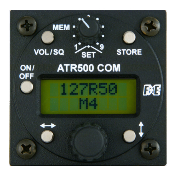
ATR500 / P/N 500-(0XX)-(0XX) / 500-(1XX)-(1XX) Operation and Installation OPERATION Controls Selection of a stored frequency (M1-M9) or manual input Setting of Volume (SET) (VOL), Squelch (SQ) Store user defined MEM/SET etc. frequencies VOL/SQ STORE ON / OFF Cursor Change... - Page 8 ATR500 / P/N 500-(0XX)-(0XX) / 500-(1XX)-(1XX) Operation and Installation Switch On press button for approx. 0,5 s On/Off Switch Off press button for approx. 3 s Navigate through Basic Settings VOL, SQ, VOL/SQ VOX, DIM und CON 1. Toggle between active and standby...
-
Page 9: On/Off
After turning-on the display appears as follows: Device Name Software-Version (Example) The ATR500 starts corresponding to the position of the rotary knob either with a specific memory position (M1-M9) or with manual frequency-entering ( The ATR500 starts with the last settings made. - Page 10 ATR500 / P/N 500-(0XX)-(0XX) / 500-(1XX)-(1XX) Operation and Installation The display of the ATR500 consists of two rows. Apart from the INIT- Menu (see 2.8.1) the upper row always shows the active frequency. The upper row presents the currently active frequency and besides...
- Page 11 ATR500 / P/N 500-(0XX)-(0XX) / 500-(1XX)-(1XX) Operation and Installation The different entries of the basic settings can be accessed with 1. VOL Volume 2. SQ Squelch 3. VOX Configuration of the threshold value in order to activate Intercom 4. DIM Background Illumination 5.
-
Page 12: Basic Settings
ATR500 / P/N 500-(0XX)-(0XX) / 500-(1XX)-(1XX) Operation and Installation Basic Settings 2.4.1 VOL – Volume By pressing once, the volume can be configured by using the lower rotary knob Range: 01 - 16 The VOL-Setting only affects the received signal, not the Intercom level, which is pre-configured by factory. -
Page 13: Dim - Background Illumination
ATR500 / P/N 500-(0XX)-(0XX) / 500-(1XX)-(1XX) Operation and Installation The higher the value, the louder you need to speak in order to activate the Intercom connection. Range: 01 – 10 In case of a noisy background or uncompensated microphones it is possible to deactivate VOX with VOX: 01. -
Page 14: Frequency Settings
ATR500 / P/N 500-(0XX)-(0XX) / 500-(1XX)-(1XX) Operation and Installation Frequency Settings 2.5.1 Manual Input turn in position With the input area (MHz or kHz) can be selected: The selected value is then adjusted with the lower rotary knob Now the modified Standby frequency can be activated by pressing (exchanges active and Standby frequency) 2.5.2... -
Page 15: Transmission
ATR500 / P/N 500-(0XX)-(0XX) / 500-(1XX)-(1XX) Operation and Installation Transmission Pushing PTT starts transmission on the selected frequency shown in the upper line. This operation is indicated by “T”. „T“ indicates correct operation of the transmitter. In order to avoid unintended transmission the transmitter stops after two minutes and the display changes from “T”... -
Page 16: Enhanced Settings
ATR500 / P/N 500-(0XX)-(0XX) / 500-(1XX)-(1XX) Operation and Installation Enhanced Settings In the following section configurations beyond the basic settings are explained. Within the INIT Menu two options are provided: reset to factory settings and the setting of the microphone sensitivity. - Page 17 ATR500 / P/N 500-(0XX)-(0XX) / 500-(1XX)-(1XX) Operation and Installation Therefore the INIT Menu is left with . The device remains powered-on and returns to normal operation. 2.8.1.1 MIC-Settings The microphone level simultaneously affects both MIC 1 and MIC 2. Therefore two equivalent standard microphones must be used to ensure successful intercom operation.
-
Page 18: Return Mode - Menu
ATR500 / P/N 500-(0XX)-(0XX) / 500-(1XX)-(1XX) Operation and Installation 2.8.2 Return Mode – Menu The return mode determines if the display automatically returns to Frequency View after changes by the user (VOL, SQ, VOX, etc.). In frequency view this affects the lower line (Standby frequency or memory position) depending on the position of . -
Page 19: Deviations In Other Variants
Operation and Installation Deviations in other variants Any operation steps described in the preceding sections are referring to ATR500 devices with a software release V2.5 or higher. The following table summarizes the differences to software releases below V2.5. Section within this... -
Page 20: Installation
ATR500 / P/N 500-(0XX)-(0XX) / 500-(1XX)-(1XX) Operation and Installation INSTALLATION Advices The following suggestions should be considered before installing. The assigned installation company will supply wiring. For diagrams refer to 3.7 Wiring. Telecommunication Data Depending on your national telecommunications legislation, the following... -
Page 21: Unpacking And Inspecting Of The Equipment
• In cooperation with a maintenance shop, location and kind of the installation are specified. The maintenance shop can supply all cables. Suitable sets of cables are available from Funkwerk Avionics GmbH. • Select a position away from heat sources. Care for adequate convection cooling. -
Page 22: Equipment Connections
ATR500 / P/N 500-(0XX)-(0XX) / 500-(1XX)-(1XX) Operation and Installation Equipment Connections One 15 pin D-SUB miniature connector includes all electrical connections, except for the antenna The (+UB)-wire has to protected by circuit breaker (2 Amp.)! 3.6.1 Microphone-Connection The device contains two microphone inputs: MIC 1: switchable („Mic.Setting“... -
Page 23: Background Illumination
ATR500 / P/N 500-(0XX)-(0XX) / 500-(1XX)-(1XX) Operation and Installation 3.6.3 Background Illumination • To switch off illumination connect „DISPLAY_LIGHTNING“ (PIN4) to „GND“ or leave it unconnected. • Illumination can be varied using an input voltage (dimmer or switch) from 0 V ... +UB connected to „DISPLAY_LIGHTNING“... -
Page 24: Wiring
ATR500 / P/N 500-(0XX)-(0XX) / 500-(1XX)-(1XX) Operation and Installation Wiring 3.7.1 Conductor Cross Section Power Supply (Power, GND): AWG20 (0,96 mm²) Signals: AWG22 (0,38 mm²) The conductors must be approved for aircraft use. 3.7.2 Wiring Single-Seater The depicted wiring diagram is performed with the cable set BSKS500A, which is available as accessory. -
Page 25: Wiring Double-Seater With Intercom
ATR500 / P/N 500-(0XX)-(0XX) / 500-(1XX)-(1XX) Operation and Installation 3.7.3 Wiring Double-Seater with Intercom The depicted wiring diagram is performed with the cable sets BSKS500M1 (1 PTT-button) or BSKS500M2 (2 PTT buttons), which are available as accessory. Cable sets can be obtained from www.funkwerk-... -
Page 26: Antenna
ATR500 / P/N 500-(0XX)-(0XX) / 500-(1XX)-(1XX) Operation and Installation Antenna 3.8.1 Antenna Selection • A VHF-COM-Antenna with an impedance of 50 Ohm is required. • Choose an antenna type compatible with the vehicle and the mounting location. • Specified features depend on proper installation of the antenna. -
Page 27: Post-Installation Check
ATR500 / P/N 500-(0XX)-(0XX) / 500-(1XX)-(1XX) Operation and Installation GND. Transmission merely operates when PTT is pressed. The suppression of background noise is only possible using differential microphones, as they are usual with modern headsets. Normal electret microphones are not suitable. -
Page 28: Starting Up
(for example M3) or the manual frequency setting mode appears: 3.12 Accessories Suitable accessories like antennas, cable sets, connectors or switches can be purchased at our online shop on www.funkwerk-avionics.com. Dokument-Nr.: 01.1251.010.71e / Revision: 2.01... -
Page 29: Drawings
ATR500 / P/N 500-(0XX)-(0XX) / 500-(1XX)-(1XX) Operation and Installation 3.13 Drawings 3.13.1 Dimensions 61 mm 163 mm 19 mm 20 mm 3.13.2 Mounting Advices Connections Area Panel Cut-out Fixing clips (spring) left / right Connector (plug) has to be clamped with both spring locks... -
Page 30: Appendix
ATR500 / P/N 500-(0XX)-(0XX) / 500-(1XX)-(1XX) Operation and Installation APPENDIX Technical Data GENERAL COMPLIANCE JTSO-2C37e,ED-23B Class 4 JTSO-2C38e,ED-23B Class C TSO-C37d, RTCA DO-186A Class 4 TSO-C38d, RTCA DO-186A Class C LBA.O.10.911/113 JTSO Height: 61 mm (2,4 in) Width: 61 mm (2,4 in) - Page 31 ATR500 / P/N 500-(0XX)-(0XX) / 500-(1XX)-(1XX) Operation and Installation TRANSMITTER 6 W (nominal) POWER OUTPUT 4 W (minimal) 70 % Modulation Capacity with 98% Limitation. MODULATION Distortion Factor< 10 % at 70 % Modulation SIDETONE OUTPUT 100 mW at 500 Ω (Headset Output)
-
Page 32: Environmental Conditions
ATR500 / P/N 500-(0XX)-(0XX) / 500-(1XX)-(1XX) Operation and Installation Environmental Conditions Characteristic DO–160D Section Cat Condition Temperature / Altitude Low ground survival 4.5.1 – 55°C temperature Low operating temperature 4.5.1 – 20°C High ground survival 4.5.2 + 85°C Temperature High Short-time Operating 4.5.2... - Page 33 ATR500 / P/N 500-(0XX)-(0XX) / 500-(1XX)-(1XX) Operation and Installation Characteristic DO–160D Section Cat Condition Induced Signal Susceptibility 19.0 Radio Frequency 20.0 Susceptibility Emission of RF Energy 21.0 Lightning Induced Transient 22.0 Susceptibility Lightning Direct Effects 23.0 No test required Icing 24.0...
- Page 34 Funkwerk Avionics GmbH Gewerbestraße 2 D-86875 Waal Germany phone.: +49-8246 9699 0 fax.: +49-8246 1049 E-mail: service@funkwerk-avionics.com www.funkwerk-avionics.com...
Need help?
Do you have a question about the ATR500 and is the answer not in the manual?
Questions and answers