
Related Manuals for Funkwerk ATR833-LCD


Summary of Contents for Funkwerk ATR833-LCD
- Page 1 ATR833 - LCD VHF Communication Transceiver P/N 833-(3xx)-(3xx) Operation and Installation (Dokument-Nr. 01.1404.010.71e)
- Page 3 ATR833-LCD / P/N 833-(3xx)-(3xx) Operation and Installation Change History Revision Date Description of Change FAV – First Release new LCD-Generation 1.00 22.06.2012 (2-Knob-HMI)- Extended control menue Sw V7.0 1.01 10.06.2013 Information about dual-watch-operation List of the Service Bulletins (SB) Services bulletins are to be inserted in the manual and to be put down in this table.
-
Page 4: Table Of Contents
ATR833-LCD / P/N 833-(3xx)-(3xx) Operation and Installation CONTENTS GENERAL ............................. 5 ........................... 5 YMBOLS .......................... 5 BBREVIATIONS ......................... 6 USTOMER UPPORT ..........................6 EATURES OPERATION ..........................7 ..........................7 ONTROLS ON/OFF ............................ 9 ............................. 9 ISPLAY ........................11 ASIC ETTINGS 2.4.1... - Page 5 ATR833-LCD / P/N 833-(3xx)-(3xx) Operation and Installation ............................ 34 IRING 4.7.1 Conductor Cross Section ..................... 34 4.7.2 Connector – Pin Allocation ................... 34 4.7.3 Wiring with Cable Harness BSKS833S/BSKS833D ............ 36 ..........................38 NTENNA 4.8.1 Antenna Selection ......................38 4.8.2 Installation Recommendation ..................
-
Page 6: General
ATR833-LCD / P/N 833-(3xx)-(3xx) Operation and Installation 1 GENERAL This manual contains information about the physical, mechanical and electrical characteristics, as well as information about installation and operation of the aeronautical VHF voice radio ATR833. 1.1 Symbols Advices whose non-observance can cause radiation damage to the human body or ignition of combustible materials. -
Page 7: Customer Support
Avionics portal www.funkwerk-avionics.com. Any suggestions for improvement of our manuals are welcome. Contact: service@funkwerk-avionics.com. Information on software updates is available at Funkwerk Avionics. 1.4 Features • VHF communication transceiver with 6W output power in 57 mm format • Frequency range 118,000 to 136,975 MHz •... -
Page 8: Operation
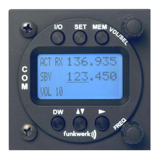
ATR833-LCD / P/N 833-(3xx)-(3xx) Operation and Installation 2 OPERATION 2.1 Controls Use together to adjust volume, squelch or other setting VOL/SEL Rotary knob Short press: Choose item to be adjusted Adjust value or select item given within with the display's lower left corner:... - Page 9 ATR833-LCD / P/N 833-(3xx)-(3xx) Operation and Installation Switch On press button for approx. 0.5 s ON/OFF Switch Off press button for approx. 2 s Activates/deactivates the mode for mutual DUAL reception standby frequency WATCH (display shows DW instead of SBY) 1.
-
Page 10: On/Off
ATR833-LCD / P/N 833-(3xx)-(3xx) Operation and Installation 2.2 ON/OFF Turn the device on with press button for 0.5 s OFF: press button for 2 s After turning-on the display shows the software version as follows: Device Name ATR833 ATR833 v7.0 Software-Version e.g. - Page 11 ATR833-LCD / P/N 833-(3xx)-(3xx) Operation and Installation Display Meaning Remark Fixed label for active frequency Label for standby frequency, Dual watch mode allows when no dual watch intermittent monitoring of activated standby frequency activity Label for standby frequency, Dual watch mode allows...
-
Page 12: Basic Settings
ATR833-LCD / P/N 833-(3xx)-(3xx) Operation and Installation Display Meaning Remark Volume of external audio- Set to 00, if no external signals device attached, to prevent noise pickup Item from user memory Substitutes standby frequency; can have name, if provided by user. Active... -
Page 13: Vol - Volume
ATR833-LCD / P/N 833-(3xx)-(3xx) Operation and Installation 2.4.1 VOL - Volume Can be reached by a long press of the button, but is also automatically chosen by the radio after 12 seconds of user inactivity. Adjusts the volume of received radio signals by turning the knob. -
Page 14: Dim - Backlight On/Off
ATR833-LCD / P/N 833-(3xx)-(3xx) Operation and Installation The default Squelch setting is 05. At higher values, weak signals could be suppressed. 2.4.3 DIM – Backlight ON/OFF By shortly pressing the key twice, with help from the rotary knob the backlight of the display can be switched on and off. -
Page 15: Dwm - Dual Watch Volume Reduction
ATR833-LCD / P/N 833-(3xx)-(3xx) Operation and Installation 2.4.5 DWM – Dual Watch Volume Reduction By shortly pressing the key four times, with help from the rotary knob the lowering of the volume level (“mute”) for receptions on the standby frequency (when having dual watch active) can be controlled. -
Page 16: Ext - Volume Of The External Audio Input
ATR833-LCD / P/N 833-(3xx)-(3xx) Operation and Installation 2.4.7 EXT - Volume of the External Audio Input By shortly pressing the key six times, with help from the rotary knob, the volume from the connected external audio signals (Warning tones, music, etc…) can be set. -
Page 17: Frequency Setting
ATR833-LCD / P/N 833-(3xx)-(3xx) Operation and Installation 2.5 Frequency Setting Frequency setting is always done by the two steps of 1. entering a new standby frequency to the desired value, and then 2. interchanging the new standby frequency and the previous active frequency by using ▲... -
Page 18: Recall A Frequency From The User Memory
ATR833-LCD / P/N 833-(3xx)-(3xx) Operation and Installation In order to speed up the entering of new frequencies, it is possible to configure the radio to allow entering of those frequencies only that are used with 25 kHz channel width. Please refer to chapter 3.1 for information on this configuration. -
Page 19: Recall A Frequency From The List Of The 10 Last Used
ATR833-LCD / P/N 833-(3xx)-(3xx) Operation and Installation 2.5.4 Recall a Frequency from the List of the 10 Last Used The radio automatically keeps track of the last 10 used active frequencies. To access this list, press twice, and select one of the 10 list entries with the turn knob. - Page 20 ATR833-LCD / P/N 833-(3xx)-(3xx) Operation and Installation • Display (Example) Step 1. Have frequency to be stored set 124.350 as active frequency 135.700 VOL 03 2. Enter memory list: 124.350 Press once shortly in order to access the user memory. (This 122.000...
-
Page 21: Dual Watch Operation
ATR833-LCD / P/N 833-(3xx)-(3xx) Operation and Installation 6. Enter the name • by changing the selected character with 124.350 124.350 , and advancing the selection with ► , just as when manually entering a MEM 07 KONSTANZ standby frequency. 7. Store the name 124.350... - Page 22 ATR833-LCD / P/N 833-(3xx)-(3xx) Operation and Installation SQL has to be set to 02 at least, as without proper squelch functionality the radio would not be able to detect whether on the active frequency a reception takes place. In order to have an audible distinction between receptions on the active and the standby frequency, it is possible to receive the receptions from the standby frequency with a lower volume.
-
Page 23: Transmission
ATR833-LCD / P/N 833-(3xx)-(3xx) Operation and Installation 2.7 Transmission By pushing the PTT button, the device starts transmission on the active frequency. The operation of the transmission is indicated by “TX” in front of the frequency used. ACT TX 123.450 135.700... -
Page 24: Configuration
ATR833-LCD / P/N 833-(3xx)-(3xx) Operation and Installation 3 CONFIGURATION A very long press of (5 seconds) accesses the configuration menu. The configuration menu is used for fundamental settings. To choose between the following settings, use the button: 1. SPC ..Channel spacing 2. -
Page 25: Con - Contrast
ATR833-LCD / P/N 833-(3xx)-(3xx) Operation and Installation This configuration item is not used for determining whether a specific frequency is used with 8.33 kHz or 25 kHz channel width, as this is done by the ATR833 automatically depending onto the frequency value entered. -
Page 26: Ptt-Button Selection
ATR833-LCD / P/N 833-(3xx)-(3xx) Operation and Installation when pressing the key again after the display turned on) or when transmitting. A short press of switches to the next configuration item, a long press of exits the configuration menu. This feature should only be used when •... -
Page 27: Behavior
ATR833-LCD / P/N 833-(3xx)-(3xx) Operation and Installation When deactivating one PTT button and microphone for transmissions, e.g. in order to keep passengers from interfering with ATC communication, don’t forget to reactivate the copilot’s PTT after end of the flight. 3.5 EXT – External Audio Input’s Behavior The external audio input can be used to feed a monaural audio signal to the amplifier for the headsets/speaker. -
Page 28: Microphone Input Sensitivity
ATR833-LCD / P/N 833-(3xx)-(3xx) Operation and Installation A short press of switches to the next configuration item, a long press of exits the configuration menu. 3.6 Microphone Input Sensitivity The microphone input sensitivity is part of the configuration menu; the access to it is described in the beginning of section 3. - Page 29 ATR833-LCD / P/N 833-(3xx)-(3xx) Operation and Installation The following microphone inputs are available at the ATR833: Microphone Input Left Right standard (headset) dynamic (glider’s gooseneck microphone) With VOX set to 5 previously, select the microphone to adjust with For each microphone input – if applicable: with running engine – speak...
-
Page 30: Tst - Test Mode
ATR833-LCD / P/N 833-(3xx)-(3xx) Operation and Installation 3.7 TST – Test Mode The last option in the setup mode is the test mode. The test mode is used by maintenance personnel only for factory-internal calibrations. 123.450 118.910 TST mode off... -
Page 31: Installation
ATR833-LCD / P/N 833-(3xx)-(3xx) Operation and Installation 4 INSTALLATION 4.1 Advices and Tips The following suggestions should be considered before installing The assigned installation company could perform wiring. For diagrams refer to section 4.7 Wiring. 4.2 Telecommunication Data The following data may be required when applying for the aircraft radio... -
Page 32: Unpacking And Inspecting The Equipment
• In cooperation with a maintenance shop, location and kind of the installation are specified. The maintenance shop can supply all cables. Suitable sets of cables are available from Funkwerk Avionics GmbH. • Select a position away from heat sources. Care for adequate convection cooling. -
Page 33: Equipment Connections
ATR833-LCD / P/N 833-(3xx)-(3xx) Operation and Installation 4.6 Equipment Connections One 25 pin D-SUB miniature connector includes all electrical connections, except for the antenna. The (+UB)-wire has to protected by circuit breaker (4 Amp. slow-blow)! 4.6.1 Microphone-Connection Microphone Input Left... -
Page 34: Audio-Input
In order to avoid disturbances while this input is not used, the respective wire needs to be short-circuited. With cable sets available from Funkwerk Avionics the external audio- input is already short-circuited by a blind plug. This blind plug can be easily removed in order to use the external audio input. -
Page 35: Wiring
ATR833-LCD / P/N 833-(3xx)-(3xx) Operation and Installation 4.7 Wiring 4.7.1 Conductor Cross Section Power Supply (Power, GND): AWG18 (0.96 mm²) Signals: AWG22 (0.38 mm²) The conductors used must be approved for aircraft installation. 4.7.2 Connector – Pin Allocation SSATR2 25-pin connector at... - Page 36 ATR833-LCD / P/N 833-(3xx)-(3xx) Operation and Installation DATA-RX RS232 RX (for Remote Control) do not connect 11 +12V-PWR Input Power Supply +12V 12 +12V-PWR Input Power Supply +12V 13 GND Ground Side of Power Supply 14 MIC-R-GND MRS− Ground Microphones Copilot/Right MRD−...
-
Page 37: Wiring With Cable Harness Bsks833S/Bsks833D
ATR833-LCD / P/N 833-(3xx)-(3xx) Operation and Installation 4.7.3 Wiring with Cable Harness BSKS833S/BSKS833D 4.7.3.1 Overview Document-No.: 01.1404.010.71e / Revision: 1.01... - Page 38 ATR833-LCD / P/N 833-(3xx)-(3xx) Operation and Installation 4.7.3.2 Connector RMT for Remote Control This connector contains the serial interface and the power supplies for the remote control unit. MSTR = Master Radio Connector for the Remote Control in the cable harness...
-
Page 39: Antenna
ATR833-LCD / P/N 833-(3xx)-(3xx) Operation and Installation 4.8 Antenna 4.8.1 Antenna Selection • A VHF-COM-Antenna with an impedance of 50 Ohm is required. • Choose an antenna type approved for the aircraft and the mounting location. • The antenna should be located far away from ELT-antennas and other VHF antennas. -
Page 40: Microphone / Intercom Settings
ATR833-LCD / P/N 833-(3xx)-(3xx) Operation and Installation 4.9 Microphone / Intercom settings The settings of MIC and VOX values are essential for Intercom. The respective configuration options are described in sections 3.6 (MIC=Microphone level) and 2.4.4 (VOX=threshold level) If the VOX automatism is deactivated with VOX=01 intercom is activated using the intercom switch (not PTT), which connects PIN 7 (intercom) of the equipment connector to GND. -
Page 41: Drawings
ATR833-LCD / P/N 833-(3xx)-(3xx) Operation and Installation 4.11 Drawings 4.11.1 Dimensions 65 mm 168 mm 20 mm 18 mm 4.11.2 Mounting Advices For mounting in panel with a thickness of 3-5 mm longer screws are available (Order- No. ZUB5). Connector Area... - Page 42 ATR833-LCD / P/N 833-(3xx)-(3xx) Operation and Installation No screws may be turned in more than max. 15mm into the device – even if no hard limit is noticeable! The D-Sub-Connector (plug) has to be clamped with both spring locks. It is recommended to additionally secure them with a cable tie.
-
Page 43: Appendix
ATR833-LCD / P/N 833-(3xx)-(3xx) Operation and Installation 5 APPENDIX 5.1 Frequency/Channel-Plan In the following table examples for operating and displayed frequencies in the range between 118.000 ... 118.100 MHz are given. This table can be continued to 136.975 MHz following the same scheme. -
Page 44: Technical Data
ATR833-LCD / P/N 833-(3xx)-(3xx) Operation and Installation 5.2 Technical Data GENERAL COMPLIANCE ETSO-2C37e,ED-23B Class 4, 6 ETSO-2C38e,ED-23B Class C, E STANDARD TSO-C37d, RTCA DO-186A Class 4, 6 TSO-C38d, RTCA DO-186A Class C, E Height: 65 mm (2.56 in) Width: 65 mm (2.56 in) - Page 45 ATR833-LCD / P/N 833-(3xx)-(3xx) Operation and Installation NF (AUDIO) - INPUT 1V/600Ω TRANSMITTER 6 W (nominal) POWER OUTPUT 4 W (minimal) HARMONIC DISTORTION < 10 % bei 70 % modulation SIDETONE OUTPUT >0.5W into 300Ω (per headphone) 2 x standard (50mV…2V) into 100Ω...
-
Page 46: Environmental Conditions
ATR833-LCD / P/N 833-(3xx)-(3xx) Operation and Installation 5.3 Environmental Conditions Characteristic DO–160D Section Cat Condition Temperature / Altitude Low ground survival 4.5.1 – 55°C temperature Low operating temperature 4.5.1 – 20°C High ground survival 4.5.2 + 85°C Temperature High Short-time Operating 4.5.2... - Page 47 ATR833-LCD / P/N 833-(3xx)-(3xx) Operation and Installation Characteristic DO–160D Section Cat Condition Induced Signal Susceptibility 19.0 Radio Frequency 20.0 Susceptibility Emission of RF Energy 21.0 Lightning Induced Transient 22.0 Susceptibility Lightning Direct Effects 23.0 No test required Icing 24.0 No test required Electrostatic Discharge (ESD) 25.0...
- Page 48 ATR833-LCD / P/N 833-(3xx)-(3xx) Operation and Installation Notes: Document-No.: 01.1404.010.71e / Revision: 1.01...
- Page 49 ATR833-LCD / P/N 833-(3xx)-(3xx) Operation and Installation Notes: Document-No.: 01.1404.010.71e / Revision: 1.01...
- Page 50 Funkwerk Avionics GmbH Heinz-Strachowitz-Str. 4 DE-86807 Buchloe Germany phone.: +49-8241 80066 0 fax.: +49-8241 80066 99 E-mail: service@funkwerk-avionics.com www.funkwerk-avionics.com...
Need help?
Do you have a question about the ATR833-LCD and is the answer not in the manual?
Questions and answers