Table of Contents
Advertisement
Quick Links
R/C Model Aircraft
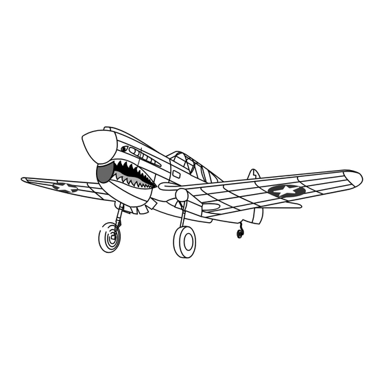
"Curtiss KittyHawk"
READ THROUGH THIS INSTRUCTION
MANUAL FIRST. IT CONTAINS
IMPORTANT INSTRUCTIONS AND
WARNINGS CONCERNING THE
ASSEMBLY
Manufactured by VQ Model Aircraft
INSTRUCTION MANUAL
Semi - Scale
P-4O
Almost ready to fly
WING SPAN APPROX :
WING AREA APPROX :
ENGINE
63 in.
676 sq. in.
: 58-61 2C ~ 70-91 4C
MADE IN VIET-NAM
Advertisement
Table of Contents

Subscribe to Our Youtube Channel
Related Manuals for Vinh Quang P-40 "Curtiss KittyHawk"


Summary of Contents for Vinh Quang P-40 "Curtiss KittyHawk"
-
Page 1: Instruction Manual
R/C Model Aircraft INSTRUCTION MANUAL Semi - Scale P-4O “Curtiss KittyHawk” Almost ready to fly WING SPAN APPROX : 63 in. READ THROUGH THIS INSTRUCTION MANUAL FIRST. IT CONTAINS WING AREA APPROX : 676 sq. in. IMPORTANT INSTRUCTIONS AND WARNINGS CONCERNING THE ASSEMBLY ENGINE : 58-61 2C ~ 70-91 4C... - Page 2 REQUIRED FOR OPERATION (Purchase separately) For 58 ~ 61 ( 2 cycle engine) For 70 ~ 91 (4 cycle engine) 12x6 – 12x7 12x7 – 14x6 Extension for aileron, throttle servo (4pcs) Silicone tube Minimum 6 channel radio for 58 ~ 61 2 cycle 70 ~ 91 4 cycle airplane (with 6 standard servos) Linkage Stopper...
-
Page 3: Bottom View
2- Main wing Securely glue together, If coming off during flights, you lose control of your airplane which leads to accidents ! BOTTOM VIEW Use epoxy glue to bury the opening 4mm Stopper 3-Main wing 3x10mm screw 4mm Stopper Nylon strap Gear mount 3x12 mm screw ..8... - Page 4 4-Main Wing LEFT - BOTTOM Bend wire for smooth “R” For right wing retracting before secure “L” the retract cover with CA For left wing glue. RIGHT- BOTTOM Using a pencil, trace around the shell where it meet the wing, then cut away only the film inside the lines which were drawn.
-
Page 5: Top View
7-Main Wing EXTENDED RETRACTED To retract gear Linkage Stopper Retract push rod Retract push rod To retract gear Retract servo Retract push rod: Cut off excess, If rod interfer, bend “C” linkage rod. 2 x 10 mm screw ....4 TOP VIEW In case of 4T engine. -
Page 6: Side-Bottom View
. Drill the hole for PP pipe. 9-Engine . Insert the Z bend into the hole on Side view throttle lever of your engine. . Use epoxy glue to secure the PP pipe on fire wall. 135 mm To throttle servo IN CASE OF 4CYCLE ENGINE FRONT VIEW... -
Page 7: Horizontal Tail
11-Horizontal Tail A’ Cut away only the film 3x10 mm screw ..2 3x10mm screw 12-Control Surface ! Securely glue together If coming off during fly, you lose control of your air plane. 2x15mm self tapping screw 2x20 mm screw CORRECT 2x20 mm screw ..4 2x15 mm self tapping screw... -
Page 8: Tail Wheel
2 mm I.D.Stopper 13-Tail wheel 3x10 mm self tapping screw Horn Plastic tail gear mount 3x10 mm screw ..2 14- Installing the RC system Fuselage-Bottom view Rudder push rod Rudder servo Switch Fuel tank Elevator push rod Elevator servo Throttle servo Elevator push rod Throttle push rod Elevator pushrod... -
Page 9: Fuel Tank
15- Linkage Bottom view Rudder rod Silicon tube or heat-shrink Elevator rod Elevator rod tube Push rod To rudder servo To elevator servo 16-Fuel tank After confirming the direction . Insert and tighten the screw. To muffler 3x35 mm screw Filler tube To engine 17- Cowling... - Page 10 18- Canopy Canopy frame stickers Instrument panel sticker Do not use to much or it will make the canopy Apply the pilot figure if white residue. you wish, into the cock-pit 19- Sheel...
- Page 11 20- Control Surface 45mm 11mm 11mm 45mm RUDDER STROKE AILERON STROKE ELEVATOR STROKE WARNING ! 21- Balance Securely install the receiver and power pack, ensuring they will not come loose or rattle during flight. 100 ~ 105 mm Never fly before checking the Cg’s required position. In order to obtain the CG specified, reposition the receiver and power pack Decal: The box art can be use for the placement of the decal...
Need help?
Do you have a question about the P-40 "Curtiss KittyHawk" and is the answer not in the manual?
Questions and answers