Table of Contents
Advertisement
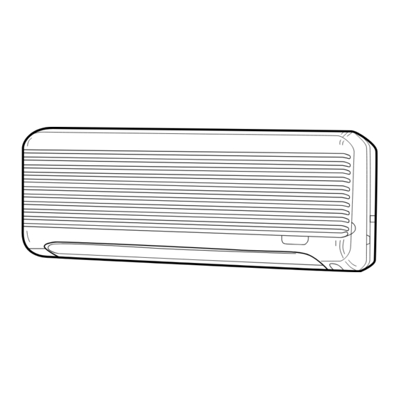
SPLIT-TYPE,HEAT PUMP AIR CONDITIONERS
TECHNICAL & SERVICE MANUAL
Wall Mounted
Series PKFY
<Indoor unit>
PKFY-P20VAM
Models
PKFY-P25VAM
INDOOR UNIT
R407C
CONTENTS
1. FEATURES ·········································2
2. SAFETY PRECAUTION ·····················3
3. PART NAMES AND FUNCTIONS······4
4. SPECIFICATION·································6
5. OUTLINES AND DIMENSIONS ·········8
6. WIRING DIAGRAM·····························9
MODEL NAME
8. TROUBLESHOOTING ······················11
9. DISASSEMBLY PROCEDURE·········16
1 0. PARTS LIST ·····································19
1998
No. OC163
Advertisement
Table of Contents

Related Manuals for Mitsubishi Electric PKFY-P20VAM


Summary of Contents for Mitsubishi Electric PKFY-P20VAM
-
Page 1: Table Of Contents
1998 SPLIT-TYPE,HEAT PUMP AIR CONDITIONERS No. OC163 TECHNICAL & SERVICE MANUAL Wall Mounted R407C Series PKFY <Indoor unit> PKFY-P20VAM Models PKFY-P25VAM CONTENTS 1. FEATURES ·········································2 2. SAFETY PRECAUTION ·····················3 3. PART NAMES AND FUNCTIONS······4 4. SPECIFICATION·································6 5. OUTLINES AND DIMENSIONS ·········8 INDOOR UNIT 6. -
Page 2: Features
FEATURES Wall Mounted Series PKFY Indoor unit Cooling capacity/Heating capacity Models kcal/h P K F Y- P 2 0 VA M 2,300 / 2,600 2,000 / 2,250 P K F Y- P 2 5 VA M 2,900 / 3,300 2,500 / 2,800 1. -
Page 3: Safety Precaution
SAFETY PRECAUTION Precautions for devices that use R407C refriqerant. Cautions for connecting with R407C outdoor unit. .Caution: · Do not use R407C piping after use it for R22. · Do not use the existing refrigerant piping. -The old refrigerant and refrigerator oil in the existing piping contains a large amount of chlorine which may cause the refrigerator oil of the new unit to deteriorate. -
Page 4: Part Names And Functions
PART NAMES AND FUNCTIONS Indoor Unit PKFY-P20VAM PKFY-P25VAM Air intake Air intake grille Filter Aute Vane Guide vane Air Outlet Remote controller [PAR-F25MA] Once the operation of the unit is set, subsequent operations can only be performed by pressing the ON/OFF button repeatedly. -
Page 5: Operation Lamp
Display In this display example on the CENTRALLY CLOCK display bottom left, a condition where all CONTROLLED display display lamps light is shown for The current time , start time and stop time can be displayed in tensecond explanation purposes although this This indicates when the unit is intervals by pressing the time switch controlled by optional features such... -
Page 6: Specification
SPECIFICATION 2-1 Specification Item Unit PKFY-P20VAM PKFY-P25VAM [,V,Hz Power Single phase ,220V-240V,50Hz Cooling capacity 2,000 2,500 Heating capacity 2,250 2,800 Cooling 0.04 Power Supply Heating 0.04 Cooling 0.20 Starting Current Heating 0.20 Exterior <munsell symbol> — Plastic munsell : <2.60Y 8.66/0.69>... - Page 7 2-2 Electrical parts specifications Model Symbol PKFY-P20VAM/PKFY-P25VAM Transformer (Primary) 50/60Hz 220-240V (Secondry) (18.4V 1.2A) Room temperature thermistor Resistance: TH21 0$C / 15k1, 10$C / 9.6k1, 20$C / 6.3k1, 25$C / 5.4k1, 30$C / 4.3k1, 40$C / 3.0k1 Liquid pipe thermistor...
-
Page 8: Outlines And Dimensions
OUTLINES AND DIMENSIONS PKFY-P20VAM,PKFY-P25VAM Unit : mm... -
Page 9: Wiring Diagram
WIRING DIAGRAM PKFY-P20VAM, PKFY-P25VAM Legend Symbol Name Symbol Name Symbol Name Indoor controller board Power supply terminal block Gas pipe thermistor TH23 (0°C / 15k1, 25°C / 5.4k1) CN32 Remote switch connector Transmission terminal block CN41 HA terminal — A connector... -
Page 10: Refrigerant System Diagram
Gas pipe thermistor TH23 Gas pipe Flare Strainer (#50mesh) Liquid pipe thermistor TH22 Heat exchanger Linear expansion valve Strainer (#100mesh) Room temperature thermistor TH21 Refrigeration pipe size (Flare connection size) Models PKFY-P20VAM, PKFY-P25VAM Item {12.7 <1/2F> Gas pipe {6.35 <1/4F> Liquid pipe... -
Page 11: Troubleshooting
TROUBLESHOOTING 6-1. How to check PKFY-P20VAM,PKFY-P25VAM Part Name Check points Room temperature Disconnect the connector, then measure the resistance using a tester. thermistor(TH21) (Sorrounding temperature 10°C~30°C) Liquid pipe thermistor(TH22) Normal Abnormal Gas pipe (Refer to the thermistor) thermistor(TH23) 4.3k ~9.6k Open or short 1Measure the resistance between the terminals using a tester.(Surrounding tempreture 25:.) -
Page 12: Linear Expansion Valve
<Thermistor Characteristic graph> < Thermistor for lower temperature > Room temperature thermistor(TH21) Thermistor for Liquid pipe thermistor(TH22) lower temperature Gas pipe thermistor(TH23) Drain sensor(THD) Thermistor R =15k' ± 3% Fixed number of B=3480k' ± 2% Rt=15exp { 3480( 273+t 15k' 9.6k' 6.3k' 5.2k'... - Page 13 <Output pulse signal and the valve operation> Output Output (Phase) Closing a valve : 1 Opening a valve : 4 The output pulse shift in above order. 1. When linear expasion valve operation stops, all output phase become OFF. 2. At phase interruption or when phase does not shift in order, motor does not rotate smoothly and motor lock, and vibrates.
- Page 14 6-2. FUNCTION OF DIPSWITCH PKFY-P20VAM, PKFY-P25VAM Operation by switch Switch Pole Function Remarks Thermistor<Intake temperature> Indoor unit Built-in remote controller Address board position Filter crogging Provide Not provide <At delivery> Filter sign indication 2,500hr 100hr 1 2 3 4 5 6 7 8 9 10...
- Page 15 Switch Operation by switch Remarks Address board SW11 1st digit Address can be set while the address unit is stopped. SW12 SW11 setting Address setting should be done when network <At delivery> SW12 remote controller (PAR-F25MA) is being used. SW12 SW11 2st digit address...
-
Page 16: Disassembly Procedure
DISASSEMBLY PROCEDURE PKFY-P25VAM Be careful on removing heavy parts. OPERATION PROCEDURE PHOTOS & ILLUSTRATIONS 1. REMOVING THE LOWER SIDE OF THE INDOOR UNIT FROM Figure 1 Figure 2 THE INSTALLATION PLATE When there is removing plate (1) Remove the corner box at right lower side of the indoor unit. - Page 17 OPERATION PROCEDURE PHOTOS & ILLUSTRATIONS 3. REMOVING THE INDOOR MICRO CONTROLLER BOARD Electrical parts box cover Photo 2 AND INDOOR POWER BOARD (1) Remove the front panel (Refer to 2). (2) Remove the electrical box cover (screw 4 (Refer to the photo 2). INDOOR MICRO CONTROLLER BOARD (1) Disconnect the following connectors on the indoor micro controller board.
-
Page 18: Operation Procedure
OPERATION PROCEDURE PHOTOS & ILLUSTRATIONS 5. REMOVING THE NOZZLE ASSEMBLE Photo 5 (1) Remove the front panel (Refer to 2). Heat exchanger Electrical parts box (2) Remove the electrical parts box cover. (3) Disconnect the connector (CN5V) on the indoor micro con Drain hose troller board. -
Page 19: 0. Parts List
PARTS LIST PANEL PARTS PKFY-P20VAM PKFY-P25VAM Q'ty / set Price Wiring Recom- Remarks No. Parts No. Parts Name Specifications PKFY-P20VAM Diagram mended Unit Amount (Drawing No.) Symbol Q'ty PKFY-P25VAM R01 22A 651 FRONT PANEL R01 22A 691 INTAKE GRILLE —... - Page 20 ELECTRICAL PARTS PKFY-P20VAM,PKFY-P25VAM FILTER CHECK MODE TEST RUN Q'ty / set Price Wiring Recom- Remarks Parts No. Parts Name Specifications Diagram PKFY- PKFY- mended Unit Amount (Drawing No.) Symbol P20VAM P25VAM Q'ty NOZZLE R01 22A 530 R01 22A 002 AUTO VANE...
- Page 21 HEAT EXCHANGER PARTS PKFY-P20VAM PKFY-P25VAM Q'ty / set Price Wiring Recom- Remarks Specifications PKFY- PKFY- No. Parts No. Parts Name Diagram mended Unit Amount (Drawing No.) P20VAM P25VAM Symbol Q'ty HEAT EXCHANGER R01 99W 480 HEAT EXCHANGER R01 00Y 480...
- Page 22 HEAD OFFICE MISTUBISHI DENKI BLDG.MARUNOUCHI TOKYO100 TELEX J24532 CABLE MELCO TOKYO cCopyright 1998 MITSUBISHI ELECTRIC ENGINEERING CO., LTD. New publication, effective Jun. 1998 Issued in Jun. 1998. No. OC163 564 Specifications subject to change without notice Printed in Japan...
Need help?
Do you have a question about the PKFY-P20VAM and is the answer not in the manual?
Questions and answers