
Related Manuals for Tweco FABRICATOR 252i


Summary of Contents for Tweco FABRICATOR 252i
- Page 1 FABRICATOR 252i ® 3-IN-1 Multi Process Welding Systems Service Manual English Canadien Français Americas Español Português (Brasil) Revision: AA Issue Date: September 4, 2013 Manual No.: 0-5156 3163339 Tweco.com...
- Page 2 We know you take pride in your work and we feel privileged to provide you with this high performance product that will help you get the job done. For more than 75 years Tweco has provided quality products you can trust, when your reputation is on the line.
- Page 3 While the information contained in this Manual represents the Manufacturer’s best judgment, the Manufacturer assumes no liability for its use. Operating Manual Number 0-5156 for: Tweco Fabricator 252i Inverter Power Supply Part No. W1004400 Tweco Fabricator 252i Inverter System Part No. W1004401...
-
Page 4: Table Of Contents
Power Source Controls, Indicators and Features ..........3-4 3.07 Advanced Features Details ................3-10 3.08 Attaching the Tweco Fusion 250A MIG Gun ..........3-15 3.09 Installing a 12.5 lb spool (8" diameter) ............3-16 3.10 Installing a Standard Spool (12" diameter) ........... 3-17 3.11... - Page 5 Main Power PCB Removal ................7-8 SECTION 8: KEY SPARE PARTS ................8-1 8.01 Fabricator 252 Power Supply Replacement Panels ........8-1 8.02 Tweco Fusion 250A MIG Gun ................8-4 APPENDIX 1: OPTIONS AND ACCESSORIES ............A-1 APPENDIX 2: FABRICATOR 252i CIRCUIT DIAGRAM ..........A-2...
- Page 6 This Page Intentionally Blank...
-
Page 7: Safety Instructions And Warnings
FABRICATOR 252i SECTION 1: SAFETY INSTRUCTIONS AND WARNINGS WARNING PROTECT YOURSELF AND OTHERS FROM POSSIBLE SERIOUS INJURY OR DEATH. KEEP CHILDREN AWAY. PACEMAKER WEARERS KEEP AWAY UNTIL CONSULTING YOUR DOCTOR. DO NOT LOSE THESE INSTRUCTIONS. READ OPERATING/INSTRUCTION MANUAL BEFORE INSTALLING, OPERATING OR SERVICING THIS EQUIPMENT. - Page 8 FABRICATOR 252i 4. Wear protective clothing made from durable, flame-resistant material (wool and leather) and foot protection. WARNING 5. Use approved ear plugs or ear muffs if noise level is ARC RAYS can burn eyes and skin; NOISE can high.
- Page 9 FABRICATOR 252i 8. Connect work cable to the work as close to the welding 2. If inside, ventilate the area and/or use exhaust at the area as practical to prevent welding current from arc to remove welding fumes and gases.
- Page 10 FABRICATOR 252i 6. Reinstall panels or guards and close doors when servicing is finished and before starting engine. WARNING Engines can be dangerous. WARNING SPARKS can cause BATTERY GASES TO EXPLODE; BATTERY ACID can burn eyes and WARNING skin. ENGINE EXHAUST GASES can kill.
-
Page 11: General Safety Information For Victor Cs Regulator
FABRICATOR 252i NOTE 3. Use heat resistant shields or other approved material to protect nearby walls or unprotected flooring from Considerations About Welding And The Effects sparks and hot metal. of Low Frequency Electric and Magnetic Fields 4. Keep an approved fire extinguisher of the proper The following is a quotation from the General Conclusions size and type in the work area. - Page 12 FABRICATOR 252i the Material Safety Data Sheet for the welding/ brazing alloy. D Personal Protection Gas flames produce infrared radiation which may have a harm ful effect on the skin and especially on the eyes. Select goggles or a mask with tempered lenses, shaded 4 or darker, to protect your eyes from injury and provide good visibility of the work.
-
Page 13: Principal Safety Standards
FABRICATOR 252i Recommended Safe Practices for the Preparation for Welding and Cutting of Containers That Have Held WARNING Hazardous Substances, American Welding Society Standard AWS F4.1, from American Welding Society, 550 DO NOT use the cylinder if you find oil, grease N.W. -
Page 14: Symbol Chart
FABRICATOR 252i 1.04 Symbol Chart Note that only some of these symbols will appear on your model. Wire Feed Function Single Phase Wire Feed Towards Workpiece With Three Phase Output Voltage OFF. Three Phase Static Frequency Converter- Welding Gun Dangerous Voltage... -
Page 15: Precautions De Securite En Soudage A L'arc
FABRICATOR 252i 1.05 Precautions De Securite En Soudage A L’arc MISE EN GARDE LE SOUDAGE A L’ARC EST DANGEREUX PROTEGEZ-VOUS, AINSI QUE LES AUTRES, CONTRE LES BLESSURES GRAVES POSSIBLES OU LA MORT. NE LAISSEZ PAS LES ENFANTS S’APPROCHER, NI LES PORTEURS DE STIMULATEUR CARDIAQUE (A MOINS QU’ILS N’AIENT CONSULTE UN MEDECIN). - Page 16 FABRICATOR 252i 12. N’utilisez que des équipements en bon état. Réparez L’arc de soudage produit une chaleur et des rayons ultraviolets intenses, susceptibles de ou remplacez aussitôt les pièces endommagées. brûler les yeux et la peau. Le bruit causé par 13.
- Page 17 FABRICATOR 252i 4. Portez des vêtements en matériaux ignifuges et dura- chauffé peuvent causer un incendie et des bles (laine et cuir) et des chaussures de sécurité. brûlures. Le contact accidentel de l’électrode ou du fil-électrode avec un objet métallique 5.
- Page 18 FABRICATOR 252i 1. Portez un écran facial ou des lunettes protectrices 1. Utilisez l’équipement à l’extérieur dans des aires ouvertes et bien ventilées. approuvées. Des écrans latéraux sont recomman- dés. 2. Si vous utilisez ces équipements dans un endroit confi- né, les fumées d’échappement doivent être envoyées...
- Page 19 FABRICATOR 252i d’autres troubles de la reproduction. Se laver 6. Réinstallez les capots ou les protecteurs et fermez les les mains après toute manipulation. portes après des travaux d’entretien et avant de faire démarrer le moteur. REMARQUE Facteurs relatifs au soudage et aux effets des AVERTISSEMENT champs magnétiques et électriques de basse...
-
Page 20: Informations Générales De Sécurité
FABRICATOR 252i 1.07 Informations Générales de Sécurité Aération Prévention D’incendie Les opérations de soudage utilisent le feu ou la combustion AVERTISSEMENT comme outil de base. Ce processus est très utile quand il est Ventilez les zones de soudage, chauffage et cor rectement contrôlé. - Page 21 FABRICATOR 252i 1. Placez la bouteille (Le schéma 1) là où elle sera utilisée. 3. Entreposez les bouteilles vides à l’écart des bou- Gardez-la en position verticale. Fixez-la sur un chariot teilles pleines. Marquez-les “VIDE” et refermez une cloison, un établi, etc.
-
Page 22: Principales Normes De Securite
FABRICATOR 252i 1.08 Principales Normes De Securite Safety in Welding and Cutting, norme ANSI Z49.1, Ame- rican Welding Society, 550 N.W. LeJeune Rd., Miami, FL 33128. Safety and Health Standards, OSHA 29 CFR 1910, Superintendent of Documents, U.S. Government Printing Office, Washington, D.C. -
Page 23: Graphique De Symbole
FABRICATOR 252i 1.09 Graphique de Symbole Seulement certains de ces symboles apparaîtront sur votre modèle. Déroulement du Fil Sous Tension Mono Phasé Alimentation du Fil Vers la Pièce de Fabrication Hors Tension Trois Phasé Hors Tension Tri-Phase Statique Soudage Torch de Tension dangereuse Fréquence Convertisseur... -
Page 24: Declaration Of Conformity
FABRICATOR 252i 1.10 Declaration Of Conformity Manufacturer: Victor Technologies International, Inc. Address: 82 Benning Street West Lebanon, New Hampshire 03784 The equipment described in this manual conforms to all applicable aspects and regulations of the ‘Low Voltage Direc- tive’ (European Council Directive 2006/95/EC) and to the National legislation for the enforcement of this Directive. -
Page 25: Section 2: Introduction
Additional copies of this manual may be purchased by contacting Tweco at the address and phone number for your location listed in the inside of or back cover of this manual. Include the Owner’s Manual number and equip- ment identification numbers. -
Page 26: Symbol Chart
FABRICATOR 252i 2.04 Symbol Chart Note that only some of these symbols will appear on your model. Wire Feed Function Single Phase Wire Feed Towards Workpiece With Three Phase Output Voltage OFF. Three Phase Static Frequency Converter- Welding Gun Dangerous Voltage... -
Page 27: Description
FABRICATOR 252i 2.07 Transportation Methods 2.05 Description The Tweco Fabricator 252i is a self contained single phase multi process welding power source that is capable of performing MIG (GMAW/FCAW), STICK (SMAW) and Lift WARNING TIG (GTAW) welding processes. The Fabricator 252i is ELECTRIC SHOCK can kill. -
Page 28: Packaged Items
• .035" (0.9 mm) • .045" (1.2 mm) - Victor® Argon Regulator / Gauge & 10 ft. (3M) Hose -Tweco WeldSkill 200 Amp electrode holder with 13 ft. (4 M) lead -Tweco WeldSkill 200 Amp ground clamp with 10 ft. (3 M) lead -Drive Rolls: • .035" / .045" (0.9 to 1.2 mm) V Grooved Lower & Flat Upper (Fitted) • .045" (1.2 mm) Flux Cored Roll... -
Page 29: Duty Cycle
6 minutes of the 10 minute period the Welding Power Source must idle and be allowed to cool. With Factory Fitted Supply Cord and Plug TIG (GTAW) MIG (GMAW) Safe Operating Region STICK (SMAW) Welding Current Max (amps) Art # A-10666 Figure 2-3: Fabricator 252i Duty Cycle with Upgraded Supply Lead and Plug Manual 0-5156 INTRODUCTION... -
Page 30: Specifications
250A @ 40%,20V 200A @ 60%, 18V 150A @ 100%, 16V Table 2-1: Fabricator 252i Specification NOTE Due to variations that can occur in manufactured products, claimed performance, voltages, ratings, all capacities, measurements, dimensions and weights quoted are approximate only. Achievable capacities and ratings in use and operation will depend upon correct installation, use, applications, maintenance and service. -
Page 31: Section 3: Installation Operation And Setup
WARNING 3.02 Location The Fabricator 252i must be electrically con- Be sure to locate the welder according to the following nected by a qualified electrical trades-person. guidelines:... -
Page 32: Electromagnetic Compatibility
208-230/50A 40% @ 250A 40% @ 250A 40% @ 230A Table 3-1: Input Power Source Leads for Fabricator 252i WARNING ELECTRIC SHOCK can kill; SIGNIFICANT DC VOLTAGE is present after removal of input power. DO NOT TOUCH live electrical parts. - Page 33 FABRICATOR 252i 2. Maintenance of Welding Equipment B. Assessment of Area The welding equipment should be routinely maintained Before installing welding equipment, the user shall make according to the manufacturer’s recommendations. All an assessment of potential electromagnetic problems in access and service doors and covers should be closed the surrounding area.
-
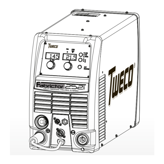
Page 34: Power Source Controls, Indicators And Features
FABRICATOR 252i 3.06 Power Source Controls, Indicators and Features Art # A-10503_AB Figure 3-1: Fabricator Control Panel Art # A-10504 Figure 3-2: Fabricator Front Connections WARNING DO NOT TOUCH the electrode wire while it is being fed through the system. The electrode wire will be at welding voltage potential. - Page 35 FABRICATOR 252i 1. Power Indicator 5. Advanced Features Button Advanced Features The green power indicator will be illuminated when the welder is turned ON and indicates the presence of power. 2. Fault Indicator Press and release the Advanced Features button to enter or exit from the advanced programming mode.
- Page 36 FABRICATOR 252i 6. Left Knob: Amperage Control (Wirespeed) required output settings for a basic range of MIG welding applications. The value may also be adjusted while a weld is in progress – if this occurs, the left display will briefly...
- Page 37 The display is also used for providing error messages to the user and showing other information, which will be The MIG Gun Adapter is the connection point for the Tweco explained in Section 5. Fusion 250A MIG Gun. Refer to section 3.08 for the correct procedure for attaching the Tweco Fusion 250A MIG Gun.
- Page 38 FABRICATOR 252i 11. Remote Control Socket The 8 pin Remote Control Socket is used to connect remote control devices to the welding power source. To make connections, align keyway, insert plug, and rotate threaded collar fully clockwise. Trigger Switch Remote Volts in...
- Page 39 FABRICATOR 252i 12. 10 Pin Accessories Socket The 10 pin Accessories Socket is used to connect remote devices such as a spool gun to the welding power source. To make connections, align keyway, insert plug, and rotate threaded collar fully clockwise.
-
Page 40: Advanced Features Details
FABRICATOR 252i Select the weld process (Control No 3) you wish to view 14. Negative Welding Output Terminal Advanced Features for. The negative welding terminal is used to connect the welding output of the power source to the appropri- Advanced... - Page 41 FABRICATOR 252i Process STICK If the welder is in Advanced Features mode and the Weld Process Selection button (Control No 3) is pressed, the welder will exit Advanced Features mode, saving any change made, and change to the next weld process function in the sequence: MIG, LIFT TIG, STICK.
- Page 42 FABRICATOR 252i Right Display Function Left Display (Factory De- Limits Comments fault Values) LOCL = Local control of the Wirespeed MIG Operator and Voltage with the machines controls. MIG/CNTL LOCL LOCL - REMT Controls REMT = Remote control of the Wirespeed and Voltage with an accessory device.
- Page 43 FABRICATOR 252i Right Display Function Left Display (Factory De- Limits Comments fault Values) Provides Arc On Hours that the power source has Arc Hour Accu- welded. The number displayed is in hours and mulated Run- 0.0 – 9999.9 read only. It will rollover to 0 once 10,000 hours time have been reached.
- Page 44 FABRICATOR 252i "Right Display Function Left Display (Factory De- Limits Comments fault Values)" In “2T” (unlatched), the unit will enter down slope mode as soon as the trigger switch is released (ie if Down Slope is set to 5.0 S, the unit will ramp down from the present welding current to zero over 5 seconds).
-
Page 45: Attaching The Tweco Fusion 250A Mig Gun
2. Push the Tweco Fusion 250A MIG Gun into MIG Gun Adaptor firmly using a twisting action. 3. Lock the Tweco Fusion 250A MIG Gun into the MIG Gun Adaptor by turning the Locking Screw clockwise in the MIG Gun Adapter within the Wire Feed Compartment to secure the Tweco Fusion 250A MIG Gun in posi- tion. -
Page 46: Installing A 12.5 Lb Spool (8" Diameter)
FABRICATOR 252i 4. If equipped, align the keyways of the MIG Gun Switch connector pigtail with the 8 pin receptacle to the right of the MIG Gun cable and plug them together. Secure by turning the locking ring to the right (clockwise ). Refer to Figure 3-8. -
Page 47: Installing A Standard Spool (12" Diameter)
FABRICATOR 252i 3.10 Installing a Standard Spool (12" diameter) As delivered from the factory, the unit is set for a 33 lb. or 12" spool. Installation of wire spool. Refer to Figure 3-10. 1. Remove Wire Spool Hub Retaining Clip. Grasp the loop and pull. -
Page 48: Inserting Wire Into The Feed Mechanism
FABRICATOR 252i 3.11 Inserting Wire into the Feed Mechanism WARNING ELECTRIC SHOCK CAN KILL! Make certain the input power is disconnected from the power source before proceeding. DO NOT reattach the input power until told to do so in these instructions. -
Page 49: Feed Roller Pressure Adjustment
Tension Adjusting knob clockwise. The use of excessive pressure may cause rapid wear of the feed roller, motor shaft and motor bearings. NOTE Genuine TWECO Velocity contact tips and liners should be used. Many non-genuine liners use inferior materials which can cause wire feed problems. 3.13 Feed Roller Alignment The bottom Feed Roll is adjustable in and out to provide for best alignment of wire as it feeds into the outlet guide. -
Page 50: Changing The Feed Roll
NOTE Installation of all styles of feed rolls for the Fabricator 252i are identical. WARNING The welding wire is electrically Hot if it is fed by depressing Fusion 250A MIG Gun switch. Electrode contact to work piece will cause an arc with MIG Gun switch depressed. -
Page 51: Input And Output Wire Guide Installation
Then loosen Output Guide Lock Screw. Install the Output Wire Guide (the longer one) by inserting the conical end part way into the Tweco Adapter from the front of the machine. Now install the MIG Gun pressing the output guide further in until the tip of the guide is as close to the feed rolls as practical. Secure the MIG Gun. Tighten the MIG Adapter Lock Nut, then tighten the Output Guide Lock Screw. -
Page 52: Wire Reel Brake
FABRICATOR 252i 3.16 Wire Reel Brake The wire reel hub incorporates a friction brake which is adjusted during manufacture for optimum braking. If it is considered necessary, adjustment can be made by turning the tri-lobe nut inside the open end of the wire reel hub. - Page 53 FABRICATOR 252i If the equipment is improperly used, hazardous conditions are created that may cause accidents. It is the users responsibility to prevent such conditions. Before handing or using the equipment, understand and comply at all times with the safe practices prescribed in this instruction.
- Page 54 FABRICATOR 252i NOTE All valves downstream of the regulator must be opened to obtain a true flow rate reading on the outlet gauge. (Welding power source must be triggered) Close the valves after the pressure has been set. Installation 1. Remove cylinder valve plastic dust seal. Clean the cylinder valve outlet of impurities that may clog orifices and damage seats before connecting the regulator.
- Page 55 FABRICATOR 252i 3. Purge air or other unwanted welding grade shielding gas from equipment connected to the regulator by indi- vidually opening then closing the equipment control valves. Complete purging may take up to ten seconds or more, depending upon the length and size of the hose being purged.
-
Page 56: Set-Up Mig (Gmaw) Welding With Gas Shielded Mig Wire
3.18 Set-up MIG (GMAW) Welding with Gas Shielded MIG Wire The Fabricator 252i is supplied with a Tweco Fusion 250 AMP air-cooled MIG Gun. The Tweco Fusion 250A MIG Gun is designed with an ergonomic handle and fewer parts to cause performance problems. The Fusion MIG Gun uses standard readily available Tweco Velocity consumable parts. -
Page 57: Set-Up For Mig (Fcaw) Welding With Gasless Mig Wire
3.19 Set-up for MIG (FCAW) Welding with Gasless MIG Wire The Fabricator 252i is supplied with a Tweco Fusion 250 AMP air-cooled MIG Gun. The Tweco Fusion 250A MIG Gun is designed with an ergonomic handle and fewer parts to cause performance problems. The Fusion MIG Gun uses standard readily available Tweco Velocity consumable parts. -
Page 58: Set-Up For Lift Tig (Gtaw) Welding
FABRICATOR 252i 1. Turn the Main ON/OFF switch OFF (located on the rear panel). 2. Check that the MIG wire size, contact tip, MIG Gun liner and drive roll groove are all the same size before fitting the MIG wire into the Power Source. - Page 59 FABRICATOR 252i NOTE The following set up is known as Straight Polarity or DC Electrode Negative. This is commonly used for DC LIFT TIG welding on most materials such as steel and stainless steel. 1. Switch the ON/OFF Switch (located on the rear panel) to OFF.
-
Page 60: Set-Up For Stick Metal Arc Welding (Smaw)
FABRICATOR 252i 3.21 Set-up for STICK Metal Arc Welding (SMAW) WARNING Before any welding is to begin, be sure to wear all appropriate and recommended safety equipment. NOTE The following set up is known as DC Electrode Positive or reverse polarity. Please consult with the STICK electrode manufacturer for specific polarity recommendations. -
Page 61: Basic Welding Guide
FABRICATOR 252i SECTION 4: Shielding Gas Nozzle (Optional) (Optional) BASIC WELDING GUIDE Molten Metal Flux Cored Molten Electrode Slag Slag 4.01 MIG (GMAW/FCAW) Basic Welding Solidified Technique Base Metal Weld Metal Two different welding processes are covered in this sec-... - Page 62 FABRICATOR 252i 10° to 20° Longitudinal 5° to 15° Angle 10° Longitudinal Angle Longitudinal 30° to 60° Angle 30° to 60° Transverse Transverse Angle Angle Direction of 90° Travel Transverse Angle Direction of Travel Vertical Fillet Welds Art # A-08995...
- Page 63 FABRICATOR 252i Secondary Adjustable Variables Direction of Gun Travel These variables cause changes in primary adjustable variables which in turn cause the desired change in the bead formation. They are: 1. Sick-out (distance between the end of the con- tact tube (tip) and the end of the electrode wire).
-
Page 64: Mig (Gmaw/Fcaw) Welding Troubleshooting
FABRICATOR 252i Electrode Wire Size Selection The choice of Electrode wire size and shielding gas used depends on the following: • Thickness of the metal to be welded • Type of joint • Capacity of the wire feed unit and Power Source • The amount of penetration required • The deposition rate required • The bead profile desired • The position of welding • Cost of the wire 4.02 MIG (GMAW/FCAW) Welding Troubleshooting... - Page 65 FABRICATOR 252i Problem 2 - Inconsistent Wire Feed WARNING Disengage the feed roll when testing for gas flow by ear. Wire feeding problems can be reduced by checking the following points. FAULT CAUSE 1 Feed roller driven by motor in the Wire spool brake is too tight.
- Page 66 A Loose welding cable connection. A Check all welding cable connections. B Low primary voltage B Contact supply authority. C Fault in power source C Have an Accredited Tweco Service Provider test then replace the faulty component. 8 Arc does not have The MIG Gun has been con-...
-
Page 67: Stick (Smaw) Basic Welding Technique
If in doubt consult flat, horizontal, vertical and overhead positions. Numer- the electrode data sheet or your nearest Accredited Tweco ous applications call for welds to be made in positions Distributor. - Page 68 FABRICATOR 252i Art # A-07690 Art# A-07693 Figure 4-14: Horizontal-Vertical (HV) Position Figure 4-17: Overhead Position, Butt Weld Art # A-07694 Figure 4-18: Overhead Position, Fillet Weld Art A-07691 Figure 4-15: Vertical Position, Butt Weld Art # A-07692 Figure 4-16: Vertical Position, Fillet Weld Joint Preparations In many cases, it will be possible to weld steel sections without any special preparation.
- Page 69 FABRICATOR 252i Open Square Butt Single Vee Butt Joint Not less than 70° Joint 1/16” (1.6mm) max Gap varies from 1/16” (1.6mm) to 3/16” (4.8mm) depending on plate thickness 1/16” (1.6mm) Not less than Single Vee Butt Joint Double Vee Butt Joint Not less than 45°...
- Page 70 FABRICATOR 252i Striking the Arc Making Welded Joints Practice this on a piece of scrap plate before going on to Having attained some skill in the handling of an electrode, more exacting work. You may at first experience difficulty you will be ready to go on to make up welded joints.
- Page 71 FABRICATOR 252i Heavy plate will require several runs to complete the Art # A-07700_AB joint. After completing the first run, chip the slag out and clean the weld with a wire brush. It is important to do this to prevent slag being trapped by the second run.
- Page 72 FABRICATOR 252i Art # A-07702 Art # A-07704 Figure 4-28: Overhead Fillet Weld Figure 4-26: Multi Run Vertical Fillet Weld Distortion Distortion in some degree is present in all forms of welding. In many cases it is so small that it is barely...
- Page 73 FABRICATOR 252i B. Expansion and Contraction of Parent Metal in B. Distribution of Stresses the Fusion Zone: Distortion may be reduced by selecting a welding While welding is proceeding, a relatively small sequence which will distribute the stresses suitably volume of the adjacent plate material is heated to a so that they tend to cancel each other out.
- Page 74 Cast Iron ENi-Cl Suitable for joining all cast irons except white cast iron. Stainless Steel E318L-16 High corrosion resistances. Ideal for dairy work etc. Table 4-4: Tweco Electrode Selection Chart 4-14 BASIC WELCING Manual 0-5156...
-
Page 75: Stick (Smaw) Welding Troubleshooting
FABRICATOR 252i 4.04 STICK (SMAW) Welding Troubleshooting FAULT CAUSE REMEDY 1 Welding current ARC FORCE is set at a val- Reduce the ARC FORCE until welding current is varying ue that causes the welding reasonably constant while prohibiting the elec-... - Page 76 FABRICATOR 252i FAULT CAUSE REMEDY 4 A groove has been A Welding current is too A Reduce welding current. formed in the base high. metal adjacent to B Welding arc is too long. B Reduce the length of the welding arc.
-
Page 77: Tig (Gtaw) Basic Welding Technique
FABRICATOR 252i 4.05 TIG (GTAW) Basic Welding Technique Gas Tungsten Arc Welding (GTAW) or TIG (Tungsten Inert Gas) as it is commonly referred to, is a welding process in which fusion is produced by an electric arc that is established between a single tungsten (non-consumable) electrode and the work piece. - Page 78 Grey num, magnesium and range, Narrower more their alloys concentrated arc. Table 4-9 NOTE The Fabricator 252i Inverter is not suited for AC TIG welding. TIG Welding Filler Rods Base Metal DC Current DC Current Tungsten Filler Rod Argon Gas...
-
Page 79: Tig (Gtaw) Welding Problems
FABRICATOR 252i 4.06 TIG (GTAW) Welding Problems FAULT CAUSE REMEDY 1 Excessive beard build up Welding current is too Increase weld current and/or faulty joint or poor penetration or poor preparation. fusion at edges of weld. 2 Weld bead too wide and Welding current is too Decrease weld current. - Page 80 9 Arc start is not smooth. A Tungsten electrode is A Select the right size electrode. Refer too large for the weld- to Table 4-7 Tweco Electrode Selection ing current. Chart. B The wrong electrode B Select the right electrode type. Refer...
-
Page 81: Section 5: Theory Of Operation
FABRICATOR 252i SECTION 5: THEORY OF OPERATION 5.01 Theory of Operation Flow Chart Table 5-1: Flow Chart Manual 0-5156 THEORY OF OPERATION... - Page 82 FABRICATOR 252i Power-up sequence of the Fabricator 252i. 1. When the main power switch for the machine is moved to the “On” position the main relays for the machine are open. Current then flows through the inrush resistors. This is a series of resistors that are sized large enough to prevent exceeding the current ratings of the bulk capacitors, but also small enough that the time to charge those capacitors is not excessive.
-
Page 83: Section 6: Trouble Shooting
FABRICATOR 252i SECTION 6: TROUBLE SHOOTING 6.01 Power Source Problems Error Codes Error Code CAUSE REMEDY Over OverTemp signal from A. Decrease duty cycle of welding activity Temperature Power board indicates B. Ensure that air vents are not blocked/obstructed Fault... - Page 84 FABRICATOR 252i 10 Inverter Output Substandard output Check to see that the two wires for voltage sensing are Fault voltage condition connected at both ends. These are from the output of the detected by controller inductor to Pin 6 of P13 and from the Negative weld termi- before weld started nal to pin 3 of P13.
- Page 85 FABRICATOR 252i Calibration An output (current, A. Check integrity of welder cables, MIG Torch or electrode Fault voltage, or motor) fault holder and retry calibration. was detected while B. Check MIG wire spool, feedplate area for wire feed issues, attempting a calibration...
-
Page 86: Tools Needed For Troubleshooting And Servicing
FABRICATOR 252i Remote Current 1. Remote not selected. 1- A. Verify "REMOTE" is selected in the Advanced Features Control not working Menu. 2. 8 pin connector problem 2- A. Verify voltage pot max to min on 8 pin connector pins 5 to 6 3. -
Page 87: Checking Unit Before Applying Power
Pre-Power Check List The following are resistance measurements on the Fabricator 252i power board while it is in an unpowered state. The first location is the placement of the positive terminal of a Digital Multimeter (DMM); the second location is for the negative terminal of the DMM and follows the word “to”... -
Page 88: Routine Service And Calibration Requirements
Section 5 of AS 1674.2 - 2007: Safety in Welding and Allied Processes-Part 2 Electrical. This includes an insulation resistance test and an earthing test to ensure the integrity of the unit is compliant with Tweco's original specifications. If equipment is to be used in a hazardous location or environments with a high risk of electrocution, then the above tests should be carried out prior to entering this location. - Page 89 AS 1674.2 - 2007, then the above tests should be carried out prior to entering this location. B. Calibration Requirements Where applicable, the tests outlined in Table 6-4 below shall be conducted by an accredited Tweco service agent. Periodic calibration of other parameters such as timing functions are not required unless a specific fault has been identified.
-
Page 90: Dip Switch Settings For Calibration
FABRICATOR 252i 6.05 Dip Switch Settings for Calibration DIP Switch SW0, control PCB Dip Switches Figure 6-2: Dip Switch Location SW0 position Function Set to OFF for Normal Operation Set to OFF for Normal Operation Table 6-3 SW0 Dip Switch functions... -
Page 91: Output Current / Amperage Calibration
FABRICATOR 252i menu. Set desired output voltage on machine Disconnect Both Polarity and set load bank for appropriate current. Connections Enable output by shorting pins D to G on 10 pin connector. 6.06 Output Current / Amperage Calibration Follow the previous steps in Sub Section 6.05 for setting the Dip Switch for Calibration before starting these steps. - Page 92 FABRICATOR 252i Left Knob Left Knob WIRESPEED WIRESPEED 13. Press and release the left knob to save the calibra- 8. The left display will show “SET AMPS”. With the tion. right knob set the amperage to just above the highest amperage expected to be used in most jobs.
-
Page 93: Output Voltage Calibration
FABRICATOR 252i 17. Locate the SERVICE Dip switch on the back of the control board and set the number "1" dip switch to the "OFF" position. Left Knob 18. Reinstall the control panel with all (4) screws. 19. Re-connect the input power to the welding power supply. -
Page 94: Wire Speed Calibration
FABRICATOR 252i 13. Press and release the left knob to save the calibra- tion. WARNING DO NOT TOUCH the electrode wire while it is being fed through the system. The electrode wire will be at welding voltage potential. Left Knob Required Equipment/Tools: • Appropriate personal protective gear: gloves, safety... - Page 95 FABRICATOR 252i 6. Pull the gun trigger and hold until wire feeding stops (Approximately 1 meter of wire will be spooled out) If trigger is released before wire stops feeding on its own, the procedure needs to Left Knob be started over. When the wire has stopped spool- ing and the left display is showing the “MEAS /...
- Page 96 FABRICATOR 252i Right Knob Right Knob ARC CONTROL ARC CONTROL 15. Turn the left knob clockwise until the left display NOTE shows “WFS / CAL”. The right display will show the word “SAVE”. The speed which is selected should also be significantly ABOVE the value used for the lower wire feed speed calibration.
-
Page 97: Control Board Quick Check
FABRICATOR 252i 1 Remove the seven top screws including the front & rear mouldings. 2 Remove the three bottom screws securing the cover panel. 3 Slightly spread the front & rear mouldings while lifting the cover. Art # A-10406 6.11 Visually Inspect Figure 6-8: Screw Location 20. - Page 98 FABRICATOR 252i Transformer Secondary Art # A12082 “D” numbers viewed on the oposite side of the PCB. 1 - D39 +15VDC Supply Inductor Transformer 2 - D55 -15VDC Supply Primary 3 - D43 +15VDC Supply 4 - D33 +24VDC Supply Figure 6-10: Connector measured voltage.
- Page 99 FABRICATOR 252i Wire Feed Speed Pot Wiper to GND (No 13.6VDC device attached) Voltage Pot Wiper to GND (No device attached) 13.6VDC 14.9VDC Trigger to GND 15VDC 15V to GND 15VDC 15V to GND 12.5VDC Fault Signal to GND (Fault not present)
-
Page 100: Main Power Pcb Connector P12 / Control Pcb P2 Connector Signals
FABRICATOR 252i Bias supply, 15VDC +/- 0.25V 0VDC Thermal Switch to GND 15VDC 15V Bias to GND -15VDC -15V Bias to GND 0VDC 0VDC Current Sense Input to GND 23.7VDC with VRD on, Weld Output + to GND 0V with VRD off Bias supply. - Page 101 FABRICATOR 252i Motor enable / MOTOR_OFF 15 V off, < 1 V on (low true) Brake enable / BRAKE_OFF Unused Multipurpose / SPARE2 Wire feed speed 1 / M_SENSE1 Unused VRD enable / VRD_SW_OFF 24 V off, < 1 V on (low true)
- Page 102 FABRICATOR 252i Control PCB Art # A-12083 Micro Processor indicator. Blinking when OK. Requires removal of left knob to view. Figure 6-11 Control PCB Signal 3.3 V Ground Program Table 6-6 Control PCB 5 Pin Connector J1 6-20 TROUBLESHOOTING Manual 0-5156...
-
Page 103: Waveforms
FABRICATOR 252i 6.14 Waveforms Voltage and current waveforms for controlled dip transfer algorithm Figure 6-12 Current and voltage for typical GMAW start in short-circuit transfer mode Figure 6-13 Manual 0-5156 TROUBLESHOOTING 6-21... - Page 104 FABRICATOR 252i Flash start for GMAW set in spray transfer range Figure 6-14 Current and voltage waveforms for PWM controlled GMAW wire feed motor Figure 6-15 6-22 TROUBLESHOOTING Manual 0-5156...
- Page 105 FABRICATOR 252i Hot start and arc force help stabilize SMAW current and voltage. Figure 6-16 Touch-sense (VRD) prevents tungsten deposits in weldment. Figure 6-17 Manual 0-5156 TROUBLESHOOTING 6-23...
- Page 106 FABRICATOR 252i Touch-sense (VRD) prevents tungsten deposits in weldment. Figure 6-18 VRD protection automatically reduces potential when no current is detected. Figure 6-19 6-24 TROUBLESHOOTING Manual 0-5156...
-
Page 107: Circuit Diagram
FABRICATOR 252i 6.15 Circuit Diagram See also appendix. Art # A-11808_AB Figure 6-20 Manual 0-5156 TROUBLESHOOTING 6-25... -
Page 108: Cleaning The Welding Power Source
FABRICATOR 252i 6.16 Cleaning the Welding Power Source Warning! Disconnect input power before maintaining. Maintain more often if used under severe conditions Each Use Visual check of torch Visual check of Consumable parts regulator and pressure Weekly Visually inspect the torch... -
Page 109: Cleaning The Feed Rolls
FABRICATOR 252i 6.17 Cleaning the Feed Rolls Clean the grooves in the drive rolls frequently. This can be done by using a small wire brush. Also wipe off, or clean the grooves on the upper feed roll. After cleaning, tighten the feed roll retaining knobs. - Page 110 FABRICATOR 252i This Page Intentionally Blank 6-28 TROUBLESHOOTING Manual 0-5156...
-
Page 111: Disassembly Procedure
FABRICATOR 252i SECTION 7: DISASSEMBLY PROCEDURE 7.01 Safety Precautions for Disassembly Read and follow safety information in Section 6.03 before proceeding. Follow anti static precautions when handling any PCB (Printed Circuit Board). Unplug unit before beginning disassembly procedure. 7.02 Control PCB (Operator Interface) Removal Read and follow safety information in Section 6.03 before proceeding with dis-... - Page 112 FABRICATOR 252i Art # A-10??? Figure 7-2: Control PCB Access 3. Flip the panel assembly over and remove the two knobs. Remove the nuts on the knob shafts. Flip the panel over again and gently spread the three (3) tabs shown below to lift the PCB from the panel surface.
-
Page 113: Input Power Cord And Power Switch / Circuit Breaker Removal
FABRICATOR 252i 7.03 Input Power Cord and Power Switch / Circuit Breaker Removal Read and follow safety information in Section 6.03 before proceeding with disassembly Unplug the unit before beginning disassembly procedure. 1. Disconnect the Input Power Cord ground wire from the Center Chassis (#1). -
Page 114: Mov/Bridge Pcb Removal
FABRICATOR 252i 7.04 MOV/Bridge PCB Removal Read and follow safety information in Section 6.03 before proceeding with disas- sembly. Follow anti static precautions when handling any PCB (Printed Circuit Board). Unplug the unit before beginning disassembly procedure. 1. Remove the two (2) mounting screws shown below (#1). -
Page 115: High Speed (Hs) Fan Shroud Removal
FABRICATOR 252i 7.05 High Speed (HS) Fan Shroud Removal Read and follow safety information in Section 6.03 before proceeding with disas- sembly. Unplug the unit before beginning disassembly procedure. Disconnect and bleed off any pressure from the Shielding Gas line. -
Page 116: Hs And Ls Fan Removal
FABRICATOR 252i 7.06 HS and LS Fan Removal Read and follow safety information in Section 6.03 before proceeding with disassembly Unplug the unit before beginning disassembly procedure. 1. Remove the four (4) screws on the rear panel that hold the two fans in place (#1). -
Page 117: Drive Motor Removal
FABRICATOR 252i 7.07 Drive Motor Removal Read and follow safety information in Section 6.03 before proceeding with disassembly Unplug the unit before beginning Disassembly procedure. 1. Use caution and cut the wire tie holding the red and black motor wires to other harnesses (#1). -
Page 118: Main Power Pcb Removal
FABRICATOR 252i 7.08 Main Power PCB Removal Read and follow safety information in Section 6.03 before proceeding with dis- assembly. Follow anti static precautions when handling any PCB (Printed Circuit Board). Unplug the unit before beginning disassembly procedure. Disconnect and blead off any Shielding Gas pressure from the system before starting this procedure. -
Page 119: Section 8: Key Spare Parts
FABRICATOR 252i SECTION 8: KEY SPARE PARTS 8.01 Fabricator 252 Power Supply Replacement Panels Art # A-10784 Figure 8-1 FABRICATOR 252i POWER SOURCE SPARE PARTS (Panels/Sheet Metal) ITEM PART NUMBER DESCRIPTION W7005323 Latch, Slide W7005366 Door, 252i W7005385 Panel, Rear, 252i... - Page 120 FABRICATOR 252i Art # 10332_AB Figure 8-2 FABRICATOR 252i POWER SOURCE SPARE PARTS (LEFT SIDE) ITEM PART NUMBER DESCRIPTION W7005311 Spool Hub Assembly W7005353 Wire Drive Assembly, 250i. (Does not include motor) 375838-002 Guide, Inlet 0.23 -1 /16" (.6 - 1.6mm)
- Page 121 FABRICATOR 252i Art # A-10668 Figure 8-3: Right side and Front Replacement Parts FABRICATOR 252i POWER SOURCE SPARE PARTS (RIGHT SIDE AND FRONT) ITEM PART NUMBER DESCRIPTION W7005330 PCB, 252i Main Power W7005318 Circuit Breaker, 50A (On Off Switch) W7005316...
-
Page 122: Tweco Fusion 250A Mig Gun
FABRICATOR 252i 8.02 Tweco Fusion 250A MIG Gun Torch Part No: FV215TA-3545 Art# A-11673_AB Figure 8-4: Tweco Fusion 250 A MIG Gun SPARE PARTS Manual 0-5156... - Page 123 MILLER is a registered trademark of Miller Electric Mfg. Co.; ESAB is a registered trademark of ESAB AB; LINCOLN is a registered trademark of LINCOLN Electric Co.; The aforementioned registered trademarks are no way affiliated with Tweco Products, Inc. or Victor Technologies. Tweco is a registered trademark of Victor Technologies.
- Page 124 FABRICATOR 252i This Page Intentionally Blank SPARE PARTS Manual 0-5156...
-
Page 125: Appendix 1: Options And Accessories
FABRICATOR 252i APPENDIX 1: OPTIONS AND ACCESSORIES Description Part Number Tweco Fusion 250A MIG Gun, 15ft 1023-1097 26 TIG torch 12.5ft (3.8m); accessory kit with 1/16”, 3/32”, 1/8” thoriated tungstens with collets, collet bodies No.5,6,7 Alumina W4013600 Nozzle - Gas Hose 9” (230mm) long with 5/8” 18 UNF male fitting, Torch switch &... -
Page 126: Appendix 2: Fabricator 252I Circuit Diagram
FABRICATOR 252i APPENDIX 2: FABRICATOR 252i CIRCUIT DIAGRAM Art # A-12093 Art # A-12093 APPENDIX Manual 0-5156... - Page 127 FABRICATOR 252i Art # A-12093 Manual 0-5156 APPENDIX...
- Page 128 FABRICATOR 252i Notes APPENDIX Manual 0-5156...
-
Page 129: Statement Of Warranty
STATEMENT OF WARRANTY Effective 08/01/2011 This warranty supersedes all previous Victor Technologies International, Inc. warranties. LIMITED WARRANTY: Victor Technologies International, Inc. warrants that its products will be free of defects in workmanship or material. Should any failure to conform to this warranty appear within the time period applicable to the Victor Technologies products as stated below, Victor Technologies shall, upon notification thereof and substantiation that the product has been stored, installed, operated, and maintained in accordance with Victor Technologies’s... -
Page 130: Warranty Schedule
WARRANTY SCHEDULE 5 Years Parts* / 3 Years Labor ArcMaster, Excelarc, Fabricator, Fabstar, PowerMaster Portafeed, Ultrafeed, Ultima 150, WC 100B * 5 years on the Original Main Power Transformer and Inductors not mounted on PCBoards. * 3 years on Power Supply Components 2 Years Parts and Labor Unless specified Auto-Darkening Welding Helmet (electronic Lens), ** 1 Month Harness Assy Victor Regulator for Fabricator 181i (No labor) - Page 132 THE AMERICAS Denton, TX USA U.S. Customer Care Ph: 1-800-426-1888 (tollfree) Fax: 1-800-535-0557 (tollfree) International Customer Care Ph: 1-940-381-1212 Fax: 1-940-483-8178 Miami, FL USA Sales Office, Latin America Ph: 1-954-727-8371 Fax: 1-954-727-8376 Oakville, Ontario, Canada Canada Customer Care Ph: 1-905-827-4515 Fax: 1-800-588-1714 (tollfree) EUROPE Chorley, United Kingdom...
Need help?
Do you have a question about the FABRICATOR 252i and is the answer not in the manual?
Questions and answers