
Related Manuals for Tweco ULTRAFEED VAF-4


Summary of Contents for Tweco ULTRAFEED VAF-4
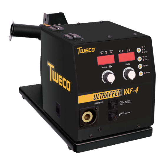
- Page 1 ULTRAFEED VAF-4 ® Wirefeeder Operating Manual English Art # A-12466 Revision: AB Issue Date: June 27, 2014 Manual No.: 0-5329 Tweco.com...
- Page 2 We know you take pride in your work and we feel privileged to provide you with this high performance product that will help you get the job done. For more than 75 years Tweco has provided quality products you can trust, when your reputation is on the line.
- Page 3 While the information contained in this Manual represents the Manufacturer’s best judgement, the Manufacturer assumes no liability for its use. Operating Manual Number 0-5329 for: Tweco ULTRAFEED VAF-4 Wirefeeder Part Number W3400002 Published by: Victor Technologies International, Inc.
-
Page 4: Table Of Contents
Rear Panel Controls and Features ..............3-8 3.08 Advanced Features Mode ................3-9 3.09 Wirefeeder Configuration for Different Power Sources ......... 3-14 3.10 Attaching Tweco No. 4 MIG Torch ..............3-15 3.11 Installing Handle Assembly ................3-16 3.12 Installing Lifting Eye Kit (Optional) ............... 3-17 3.13 Installing Wire Spool Cover (optional) ............ - Page 5 5.01 Equipment Identification ................. 5-1 5.02 How To Use This Parts List ................5-1 5.03 Replacement Parts (without wirefeed plate) ........... 5-2 5.04 Replacement Parts- Wirefeed Plate ..............5-3 APPENDIx 1: CONNECTION DIAGRAM ..............A-1 TWECO - LIMITED WARRANTY TERMS...
-
Page 7: Section 1: Safety Instructions And Warnings
ULTRAFEED VAF-4 SECTION 1: SAFETY INSTRUCTIONS AND WARNINGS WARNING PROTECT YOURSELF AND OTHERS FROM POSSIBLE SERIOUS INJURY OR DEATH. KEEP CHILDREN AWAY. PACEMAKER WEARERS KEEP AWAY UNTIL CONSULTING YOUR DOCTOR. DO NOT LOSE THESE INSTRUCTIONS. READ OPERATING/INSTRUCTION MANUAL BEFORE INSTALLING, OPERATING OR SERvICING THIS EQUIPMENT. - Page 8 ULTRAFEED VAF-4 3. Use protective screens or barriers to protect others from flash and glare; warn others not to watch the arc. WARNING 4. Wear protective clothing made from durable, ARC RAYS can burn eyes and skin; NOISE flame-resistant material (wool and leather) and foot can damage hearing.
- Page 9 ULTRAFEED VAF-4 6. Be aware that welding on a ceiling, floor, bulkhead, 1. Keep your head out of the fumes. Do not breathe or partition can cause fire on the hidden side. the fumes. 7. Do not weld on closed containers such as tanks or 2.
- Page 10 ULTRAFEED VAF-4 7. Keep protective cap in place over valve except when 3. Have only qualified people remove guards or cylinder is in use or connected for use. covers for maintenance and troubleshooting as necessary. 8. Read and follow instructions on compressed 4.
-
Page 11: General Safety Information For Victor Regulator
ULTRAFEED VAF-4 1.02 General Safety Information for victor Regulator WARNING Fire Prevention WARNING: This product contains chemicals, including Welding and cutting operations use fire or combustion lead, known to the State of California to cause birth as a basic tool. The process is very useful when properly defects and other reproductive harm. - Page 12 ULTRAFEED VAF-4 ventilation Compressed Gas Cylinders The Department of Transportation (DOT) approves the design and manufacture of cylinders that contain gases WARNING used for welding or cutting operations. Ade quately ventilate welding, heating, and 1. Place the cylinder (Figure 1-1) where you will cutting work areas to prevent accumula- use it.
-
Page 13: Principal Safety Standards
ULTRAFEED VAF-4 4. NEVER use compressed gas cylinders without 1.03 Principal Safety Standards a pressure reducing regulator attached to the cylinder valve. Safety in Welding and Cutting, ANSI Standard Z49.1, from American Welding Society, 550 N.W. LeJeune Rd., 5. Inspect the cylinder valve for oil, grease, and Miami, FL 33126. -
Page 14: Symbol Chart
ULTRAFEED VAF-4 1.04 Symbol Chart Note that only some of these symbols will appear on your model. Wire Feed Function Single Phase Wire Feed Towards Workpiece With Three Phase Output Voltage Off. Three Phase Static Frequency Converter- Dangerous Voltage Welding Gun... -
Page 15: Precautions De Securite En Soudage A L'arc
ULTRAFEED VAF-4 1.05 Precautions De Securite En Soudage A L’arc MISE EN GARDE LE SOUDAGE A L’ARC EST DANGEREUx PROTEGEZ-vOUS, AINSI QUE LES AUTRES, CONTRE LES BLESSURES GRAvES POSSIBLES OU LA MORT. NE LAISSEZ PAS LES ENFANTS S’APPROCHER, NI LES PORTEURS DE STIMULATEUR CARDIAQUE (A MOINS QU’ILS N’AIENT CONSULTE UN MEDECIN). - Page 16 ULTRAFEED VAF-4 9. N’enroulez pas de câbles électriques autour de votre corps. AvERTISSEMENT 10. N’utilisez qu’une bonne prise de masse pour la mise à la terre de la pièce à souder. LE RAYONNEMENT DE L’ARC PEUT BRÛLER LES YEUX ET LA PEAU; LE BRUIT PEUT 11.
- Page 17 ULTRAFEED VAF-4 2. Portez des lunettes de sécurité approuvées. Des écrans latéraux sont recommandés. AvERTISSEMENT 3. Entourez l’aire de soudage de rideaux ou de cloisons LE SOUDAGE PEUT CAUSER UN INCENDIE pour protéger les autres des coups d’arc ou de OU UNE EXPLOSION l’éblouissement;...
- Page 18 ULTRAFEED VAF-4 8. Lisez et respectez les consignes relatives aux bouteilles de gaz comprimé et aux équipements AvERTISSEMENT connexes, ainsi que la publication P-1 de la CGA, identifiée dans la liste de documents ci-dessous. LES ETINCELLES ET LES PROJECTIONS BRULANTES PEUVENT CAUSER DES BLES- SURES.
- Page 19 ULTRAFEED VAF-4 5. Utilisez la polarité correcte (+ et –) de l’accumulateur. AvERTISSEMENT DES PIECES EN MOUVEMENT PEUVENT AvERTISSEMENT CAUSER DES BLESSURES. LA VAPEUR ET LE LIQUIDE DE REFROID- Des pièces en mouvement, tels des ventila- ISSEMENT BRULANT SOUS PRESSION teurs, des rotors et des courroies peuvent PEUVENT BRULER LA PEAU ET LES YEUX.
-
Page 20: Informations Générales De Sécurité
ULTRAFEED VAF-4 des faits scientifiques visant à atténuer ou éviter des risques potentiels ». AvERTISSEMENT Pour atténuer les champs magnétiques sur les lieux N’effectuez d’opérations de soudage de travail, respectez les procédures qui suivent : JAMAIS sur un récipient qui a contenu des liquides 1. - Page 21 ULTRAFEED VAF-4 manches et poches boutonnés. Il ne faut pas remonter AvIS vos manches ou les pantalons à revers. Ce document CGA p. t peut être obtenu en écrivant à “Compressed Gas Association”, Quand vous travaillez dans un environnement non 4221 Walney Roed, 5th Floor.
-
Page 22: Principales Normes De Securite
ULTRAFEED VAF-4 1.08 Principales Normes De Securite Safety in Welding and Cutting, norme ANSI Z49.1, American Welding Society, 550 N.W. LeJeune Rd., Miami, FL 33128. Safety and Health Standards, OSHA 29 CFR 1910, Superintendent of Documents, U.S. Government Printing Office, Washington, D.C. -
Page 23: Graphique De Symbole
ULTRAFEED VAF-4 1.09 Graphique de Symbole Seulement certains de ces symboles apparaîtront sur votre modèle. Déroulement du Fil Sous Tension Mono Phasé Alimentation du Fil Vers la Pièce de Fabrication Hors Tension Trois Phasé Hors Tension Tri-Phase Statique Soudage Torch de Tension dangereuse Fréquence Convertisseur... - Page 24 ULTRAFEED VAF-4 This Page Intentionally Blank 1-18 Manual 0-5329 SAFETY INSTRUCTIONS AND WARNINGS...
-
Page 25: Section 2: Introduction
Additional copies of this manual may be purchased by contacting Tweco at the address and phone number for your location listed in the inside back cover of this manual. Include the Owner’s Manual number and equipment iden- tification numbers. -
Page 26: Description
Tweco. The user of this equipment shall have the sole The Ultrafeed VAF-4’s sheet metal box totally encloses the responsibility for any malfunction which results from solid state control circuitry. -
Page 27: Specifications
Achievable capacities and ratings in use and operation will depend upon correct installation, use, applications, maintenance and service. In the interest of continuous improvement, Tweco reserves the right to change the specifications or design of any of its products without prior notice. - Page 28 ULTRAFEED VAF-4 Other Accessories Accessories Part Number Description Suitable for spools up to 300mm diameter. Spool Cover Assy W4016301 Contains plastic spool cover and all necessary mounting hardware. Lifting Eye Kit W4016701 Electrically insulated. Heavy duty, large castor wheel trolley for moving the...
-
Page 29: Section 3: Installation, Operation And Setup
ULTRAFEED VAF-4 SECTION 3: INSTALLATION, OPERATION AND SETUP 3.03 ventilation 3.01 Environment These units are designed for use in environments with increased hazard of electric shock as outlined in IEC 60974-5. WARNING Since the inhalation of welding fumes can be A. - Page 30 ULTRAFEED VAF-4 2. Maintenance of Welding Equipment B. Assessment of Area The welding equipment should be routinely maintained Before installing welding equipment, the user shall make according to the manufacturer’s recommendations. All an assessment of potential electromagnetic problems in access and service doors and covers should be closed the surrounding area.
-
Page 31: Front Panel Controls, Indicators And Features
ULTRAFEED VAF-4 3.06 Front Panel Controls, Indicators and Features Art # A-12467 Figure 3-1 Front Panel View WARNING DO NOT TOUCH the electrode wire while it is being fed through the system. The electrode wire will be at welding voltage potential. - Page 32 ULTRAFEED VAF-4 the adjusted value as the knob is turned, and will automatically revert back to show the weld current measurements when the knob is not being turned. Turn the left knob either clockwise to increase WFS or counterclockwise to decrease WFS by increments of 3.94 IPM.
- Page 33 ULTRAFEED VAF-4 8. Left Digital Display Left display is a 4- digit display. In advanced programming mode, this display is used to display advanced features details or simply "----". Please refer to Section 3.08 for Advanced Features Details. When welding, this digital meter will display WFS in Inches Per Minute (IPM) or Metres Per Minute (MPM) and actual welding amperage of the power source; it can also simply display "----" when the VAF-4 is connected to a power source...
- Page 34 ULTRAFEED VAF-4 NOTE In Advanced Features Mode Trigger Mode and SCH1-SCH2 can't be changed. In Spot Mode Stitch Mode is not available. Crater is only available in 4T Trigger Mode. 11. SCH 1-SCH 2 Button This allows the user to save parameter settings in either Schedule 1 (SCH 1) or Schedule 2 (SCH 2) locations. Press the button to select either SCH 1 or SCH 2.
- Page 35 ULTRAFEED VAF-4 15. Remote Control Socket The 8 pin Remote Control Socket is used to connect remote control devices to the welding power source. To make connections, align keyway, insert plug, and rotate threaded collar fully clockwise. Trigger Switch Remote Volts in...
-
Page 36: Rear Panel Controls And Features
ULTRAFEED VAF-4 Keyway 3.07 Rear Panel Controls and Features Figure 3-5 Pin Identification Art # A-12468 Control Cable Function Figure 3-4 Rear Panel View Contactor + (Shorted to B 17. ON/ OFF Switch to turn ON Power Source) Contactor- (Shorted to A to Press this switch to turn ON or turn OFF the Wirefeeder. -
Page 37: Advanced Features Mode
ULTRAFEED VAF-4 3.08 Advanced Features Mode Enter Advanced Features Mode by pressing both the left knob and right knob at the same time for more than 1.2 seconds. NOTE In Advanced Features Mode the Trigger Mode Control Button, SCH 1-SCH 2 button is inactive. - Page 38 ULTRAFEED VAF-4 Advanced Feature Left Display Right Display Feature Description Parameter / Selection Ramp Time This is used to set the time to ramp from the creep wire feed speed to the selected wirefeed speed setting. 0.1 to 1.0 seconds Default Ramp Time = 0.2 sec...
- Page 39 ULTRAFEED VAF-4 Advanced Feature Left Display Right Display Feature Description Parameter / Selection Crater Wirefeed Speed (only if Crater mode is ON) This sets the reduced wire speed during crater operation in 4T at the 0 – 100% of end of the weld.
- Page 40 ULTRAFEED VAF-4 Advanced Feature Left Display Right Display Feature Description Parameter / Selection Wirefeed Speed Units This allows setting of the Wirefeed Speed Meter to display in IPM or MPM units. Default Wirefeed Speed = IPM IPM (inches per minute)
- Page 41 ULTRAFEED VAF-4 Advanced Feature Left Display Right Display Feature Description Parameter / Selection Restore Factory Defaults This resets all the user adjustable values in this table (except Arc Hour Accumulated Runtime) to the Factory Default Values. Restore Factory Default No / YES CAUTION Schedule SCH1 &...
-
Page 42: Wirefeeder Configuration For Different Power Sources
When S6=ON(1), calibration functions in Advanced Features Mode is enabled; when S6=OFF(0), calibration functions are disabled. NOTE When S1=OFF(0),S2=ON(1), WFS Setting is applicable for Ultrafeed VAF-4 and it ranges from 50 IPM to 875 IPM. 3-14 INSTALLATION, OPERATION AND SETUP... -
Page 43: Attaching Tweco No. 4 Mig Torch
1. Insert the 4 pin plug into the 4 Pin Trigger Socket, and rotate threaded collar fully clockwise to lock the plug into position. 2. Fit the Tweco No. 4 MIG torch to the Wirefeeder by pushing the MIG Torch Connector into the Tweco No. 4 Torch Adaptor and secure it by tightening the Thumb Screw supplied. -
Page 44: Installing Handle Assembly
ULTRAFEED VAF-4 3.11 Installing Handle Assembly WARNING This handle is not designed to lift wirefeeder by mechanical means. Handle is to be used for Lifting by Hand Only. For Mechanical Lifting use Lifting Eye Kit W4016700. The following components are included:... -
Page 45: Installing Lifting Eye Kit (Optional)
ULTRAFEED VAF-4 3.12 Installing Lifting Eye Kit (Optional) The following components are included: Description Quantity Lifting Eye Insulator Plate Bolt, M8 × 40 (with torque 45~59 N.m.) Flat Washer (smaller), M8 (with torque 45~59 N.m.) Flat Washer (larger), M8 (with torque 45~59 N.m.) Insulator Washer, M8 (with torque 45~59 N.m.) -
Page 46: Installing Wire Spool Cover (Optional)
ULTRAFEED VAF-4 3.13 Installing Wire Spool Cover (optional) The following components are included in this kit: Item Description Quantity Bolt, M12 x 30 Star Washer, M12 Flat Washer, M12 Screw, Countersunk, M5 x 12 Spool Cover Mounting Bracket Spool Cover... - Page 47 ULTRAFEED VAF-4 Spool cover is assembled in the following steps: 1. Remove the spool hub assembly. a. Remove the clip from the spool hub. b. Unscrew the 3-lobe screw. c. Remove the spool hub parts and the spacer in the following sequence. Note that the spacer is not required when fitting the spool cover.
- Page 48 ULTRAFEED VAF-4 4. Install the spool hub component parts over the spool hub shaft in the following sequence. Spool Hub Spring 3-lobe Screw Flat Washer Retaining Clip Keyed Washer Friction Washer Art # A-12478 Figure 3-15 Spool Hub Assembly WARNING Fully tighten all fasteners.
-
Page 49: Installing Welding Wire Spool
ULTRAFEED VAF-4 3.14 Installing Welding Wire Spool WARNING Fully tighten all fasteners. There are 3 holes on the spool hub support. The top screw hole is for installing a coil of 16" (66lbs) diameter. In this case a 66lbs coil holder must be used. The 66lbs coil holder is attached to the spool hub in the same way as for a 12" spool, then the coil is placed over the 66lbs coil holder & locked in place. The middle hole is for installing a spool of 12" diameter (as shown in Figure 3-17). The bottom hole is for installing a spool of 8" diameter. As delivered from the factory, the unit has the spool hub fitted into the middle (12" spool) position. -
Page 50: Wire Reel Brake
ULTRAFEED VAF-4 3.15 Wire Reel Brake The wire reel hub incorporates a 3-lobe screw which is adjusted during manufacture for optimum braking. If it is considered necessary, adjustment can be made by turning the 3-lobe Screw inside the open end of the hub clockwise to tighten the brake. -
Page 51: Inserting Wire Into Feed Mechanism
ULTRAFEED VAF-4 3.16 Inserting Wire into Feed Mechanism WARNING ELECTRIC SHOCK CAN KILL! Make certain the input power is disconnected from the power source before proceeding. Do not reattach the input power until told to do so in these instructions. -
Page 52: Installing And Changing The Feed Roll / Removing Inlet Guide & Torch Adaptor
10. To remove the Tweco No. 4 torch adaptor remove the thumb screw as shown in the figure below then use the 3mm allen key to remove the set screw that fixes the torch adaptor. -
Page 53: Shielding Gas Regulator Operating Instructions
ULTRAFEED VAF-4 NOTE All grooved Feed Rolls have their wire size or range stamped on the side of the roll. On rolls with different size grooves, the outer (visible when installed) stamped wire size indicates the groove in use. WARNING The welding wire is electrically Hot if it is fed by depressing MIG Gun switch. - Page 54 ULTRAFEED VAF-4 User Responsibilities This equipment will perform safely and reliable only when installed, operated and maintained, and repaired in accordance with the instructions provided. Equipment must be checked periodically and repaired, replaced, or reset as necessary for continued safe and reliable performance. Defective equipment should not be used. Parts that are broken, missing, obviously worn, distorted, or contaminated should be replaced immediately.
- Page 55 ULTRAFEED VAF-4 Operation With the regulator connected to cylinder or pipeline, and the adjustment screw/knob fully disengaged, pressurize as follows: 1. Stand to one side of regulator and slowly open the cylinder valve. If opened quickly, a sudden pressure surge may damage internal regulator parts.
-
Page 56: Wire Feeder Set Up Mig (Gmaw) Welding With Gas Shielded Mig Wire
ULTRAFEED VAF-4 3.20 Wire Feeder Set Up MIG (GMAW) Welding with Gas Shielded MIG Wire Power Source Connections A. Remove all packaging materials. Do not block the air vents at the front or rear of the Power Source. B. Connect the work lead to the negative welding terminal (-) [positive welding terminal(+) for flux cored electrode wire]. - Page 57 ULTRAFEED VAF-4 WARNING DO NOT WEAR GLOVES WHILE THREADING THE WIRE OR CHANGING THE WIRE SPOOL. H. Lower the pressure levers and with the gun lead reasonably straight, feed the electrode wire through the gun. Fit the appropriate contact tip, eg a .035" tip for .035" wire. Press the INCH button to feed the wire through the gun.
-
Page 58: Wire Feeder Set Up Mig (Gmaw) Welding With Gasless Mig Wire
ULTRAFEED VAF-4 3.21 Wire Feeder Set Up MIG (GMAW) Welding with Gasless MIG Wire Power Source Connections A. Remove all packaging materials. Do not block the air vents at the front or rear of the Power Source. B. Connect the work lead to the positive welding terminal(+). If in doubt, consult the electrode wire manufacturer. - Page 59 ULTRAFEED VAF-4 WARNING If the Gun Trigger is used to feed wire through the gun, the electrode wire will be at welding voltage potential while it is being fed through the wirefeeder system. WARNING Before connecting the work clamp to the work piece make sure the mains power supply is switched off.
-
Page 60: Prewelding Procedure
Follow all installation instructions for the wire feeder, the welding power source, and the welding gun before attempt- ing to operate the Ultrafeed VAF-4. 1. Make sure all necessary connections have been made (Refer to Section 3.01 of this manual). -
Page 61: Welding- 2T Operation
ULTRAFEED VAF-4 3.24 Welding- 2T Operation Position the welding gun above the workpiece and depress the gun switch trigger. Depressing the gun switch trigger enables the gas valve. When preflow ends, wire feed motor and power source are enabled; the welding process begins. -
Page 62: Welding- 4T Operation
ULTRAFEED VAF-4 3.26 Welding- 4T Operation Welding- 4T Operation (Crater=ON) Position the welding gun above the workpiece, depress the gun switch trigger, it enables power source and gas valve, and the wire will begin feeding. Welding arc is established. Release the gun switch trigger and the welding process continues. -
Page 63: Stitch Operation
ULTRAFEED VAF-4 3.27 Stitch Operation After selecting stitch operation in advanced features menu, select 2T Stitch or 4T Stitch by pressing 2T/ 4T button on front panel. 2T Stitch Operation Position the welding gun above the workpiece and depress the gun switch trigger. Depressing the gun switch trigger enables the gas valve. -
Page 64: Ptc (Positive Temperature Coefficient) Protection Of Power Source Contactor Control Output
Control Output The Power Source Contactor control circuit on the Ultrafeed VAF-4 provides a relay closure to the power source through pins A and B of the 19 pin control cable. This allows the welding wire to become electrically ‘HOT’ when the gun switch trigger on the welding gun is pulled. -
Page 65: Section 4: Service
ULTRAFEED VAF-4 SECTION 4: SERvICE 4.04 Troubleshooting Guide 4.01 Cleaning The Unit NOTE Periodically, clean the inside of the wire feeder and feedhead assembly by using a vacuum cleaner or clean, Refer to the Connection Diagram in the Ap- dry compressed air of not more than 25 psi (172 kPa) pendix chapter of this manual for graphical as- pressure. -
Page 66: Error Codes And Remedies
2. If ERR 01 appears again with Fault light flashes the next weld or metallic dust at a rate of build up cannot be located then approximately 0.5 contact your Accredited TWECO second ON, 0.5 Service Provider to investigate second OFF. the fault. 02-- Control cable 1. - Page 67 Tachometer and motor control PCB is correctly connected. Reconnect Wirefeeder to Power Source and if ERR 05 appears again with the next weld then contact your Accredited TWECO Service Provider to investigate the fault. 06-- Output current of 1. Current running through 1.
-
Page 68: Mig (Gmaw/Fcaw) Basic Welding Technique
ULTRAFEED VAF-4 4.06 MIG (GMAW/FCAW) Basic Welding Technique Two different welding processes are covered in this section (GMAW and FCAW), with the intention of providing the very basic concepts in using the Mig mode of welding, where a MIG Torch is hand held, and the electrode (welding wire) is fed into a weld puddle, and the arc is shielded by an inert welding grade shielding gas or inert welding grade shielding gas mixture. - Page 69 ULTRAFEED VAF-4 Preselected variables 5° to 15° Preselected variables depend upon the type of material Longitudinal Angle being welded, the thickness of the material, the welding 30° to 60° Transverse Angle position, the deposition rate and the mechanical proper- ties. These variables are:...
- Page 70 ULTRAFEED VAF-4 Nozzle Angle and can be either trailing (pulling) Setting of the Power Source or leading (pushing). Whether the operator is left Power source and Wirefeeder setting requires some prac- handed or right handed has to be considered to...
-
Page 71: Mig (Gmaw/Fcaw) Welding Troubleshooting
ULTRAFEED VAF-4 4.07 MIG (GMAW/FCAW) Welding Troubleshooting Solving Problems Beyond the Welding Terminals The general approach to fix Gas Metal Arc Welding (GMAW) problems is to start at the wire spool then work through to the MIG Torch. There are two main areas where problems occur with GMAW; Porosity and Inconsistent wire feed. - Page 72 ULTRAFEED VAF-4 Problem 2 - Inconsistent Wire Feed WARNING Disengage the feed roll when testing for gas flow by ear. Wire feeding problems can be reduced by checking the following points. FAULT CAUSE Feed roller driven by motor in the cabinet Wire spool brake is too tight.
- Page 73 Check all welding cable connections. Low primary voltage Contact supply authority. Fault in power source Have an Accredited TWECO Service Provider test then replace the Arc does not have a crisp Torch been Connect the MIG torch to the positive (+) welding terminal...
-
Page 74: Troubleshooting
Table in Section 4.05. fault indicator is lit when Wirefeeder is turned ON. Power Indicator light Faulty Indicator light on display Have an Accredited TWECO Service is not lit but welding PCB. Provider investigate the fault. arc can be established. Power ON Indicator... - Page 75 Torch conduit liner or worn contract torch trigger switch is jam). tip. Replace faulty components. depressed. Have an Accredited TWECO Service Faulty motor control PCB. Provider investigate the fault. Wire feeds when the Poor or no work lead contact. Clean work clamp area and ensure torch trigger switch good electrical contact.
- Page 76 Refer to Section 4.05 Error Codes feed the yellow Fault operated. and Remedies ERR 01. indicator is lit and ERR Have an Accredited TWECO Service 01 is displayed Provider investigate the fault. 14 Circuit breaker/s has Short circuit on the 42 or 115VAC...
-
Page 77: Section 5: Parts List
ULTRAFEED VAF-4 SECTION 5: PARTS LIST 5.01 Equipment Identification All identification numbers as described in the Introduction Chapter must be furnished when ordering parts or making inquiries. This information is found on the nameplate attached to the equipment. Be sure to include any dash numbers following the Specification or Assembly numbers. -
Page 78: Replacement Parts (Without Wirefeed Plate)
Socket, 19 Pin, Male, Panel Mtg W7005715 Socket Panel, Dinse, Male, 50mm W7005716 SPOOL HUB ASSY W7005609 Wire Guide, Outlet, 0.8-1.2, WF W4017700 Adaptor, Tweco No. 4 W4017800 Handle Kit W7005717 Art # A-12485 Figure 5-1 Replacement Parts (without wirefeed plate) PARTS LIST Manual 0-5329... -
Page 79: Replacement Parts- Wirefeed Plate
ULTRAFEED VAF-4 5.04 Replacement Parts- Wirefeed Plate Item # Description Part Number Motor, 42V, WF W7005713 Wire Drive Assy, 4R, WF W7005707 Wire Guide, Inlet, 0.8-1.6, WF W7005710 Wire Guide, Centre, 0.8-1.6, WF W7005711 Feed Roll Refer to Section 2.09... - Page 80 ULTRAFEED VAF-4 This page intentionally blank PARTS LIST Manual 0-5329...
-
Page 81: Appendix 1: Connection Diagram
ULTRAFEED VAF-4 APPENDIx 1: CONNECTION DIAGRAM Manual 0-5329 APPENDIX... -
Page 82: Tweco - Limited Warranty Terms
“Purchaser” that its products will be free of defects in workmanship or material. Should any failure to conform to this warranty appear within the time period applicable to the Tweco products as stated below, Tweco shall, upon notification thereof and substantiation that the product has been stored, installed, oper- ated, and maintained in accordance with Tweco’s specifications, instructions, recommendations and recognized... -
Page 83: Warranty Schedule
Warranty SCHEDULE 5 Years Parts* / 3 Years Labor ArcMaster, Excelarc, Fabricator, Fabstar, PowerMaster Portafeed, Ultrafeed, Ultima 150, WC 100B * 5 years on the Original Main Power Transformer and Inductors not mounted on PCBoards. * 3 years on Power Supply Components 2 Years Parts and Labor Unless specified Auto-Darkening Welding Helmet (electronic Lens), ** 1 Month Harness Assy Victor Regulator for Fabricator 141i (No labor) - Page 84 THE AMERICAS Denton, TX USA U.S. Customer Care Ph 1-800-426-1888 (tollfree) Fax: 1-800-535-0557 (tollfree) International Customer Care Ph 1-940-381-1212 Fax: 1-940-483-8178 Miami, FL USA Sales Office, Latin America Ph 1-954-727-8371 Fax: 1-954-727-8376 Oakville, Ontario, Canada Canada Customer Care Ph 1-905-827-4515 Fax: 1-800-588-1714 (tollfree) EUROPE Chorley, United Kingdom...
Need help?
Do you have a question about the ULTRAFEED VAF-4 and is the answer not in the manual?
Questions and answers