
Related Manuals for Tweco fabricator 211i


Summary of Contents for Tweco fabricator 211i
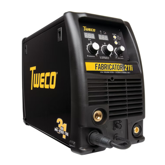
- Page 1 FABRICATOR 211i ® 3-IN-1 Multi Process Welding Systems Service Manual Revision: AD Issue Date: June 19, 2015 Manual No.: 0-5226 Tweco.com...
- Page 2 We know you take pride in your work and we feel privileged to provide you with this high performance product that will help you get the job done. For more than 75 years Tweco has provided quality products you can trust, when your reputation is on the line.
- Page 3 While the information contained in this Manual represents the Manufacturer’s best judgment, the Manufacturer assumes no liability for its use. Service Manual Number 0-5226 for: Tweco Fabricator 211i Inverter Power Supply Part Number W1004206 Tweco Fabricator 211i Inverter System Part Number W1004207 Published by: Victor Technologies International, Inc.
-
Page 4: Table Of Contents
TABLE OF CONTENTS SECTION 1: SAFETY INSTRUCTIONS AND WARNINGS ............1-1 1.01 Arc Welding Hazards ..................1-1 1.02 Principal Safety Standards ................1-5 1.03 Symbol Chart ....................1-6 1.04 Servicing Hazards ................... 1-7 1.05 EMF Information ..................... 1-9 SECTION 2: INTRODUCTION .................. - Page 5 Installing Case ....................7-6 SECTION 8: KEY SPARE PARTS ................... 8-1 8.01 Power Source Spare Parts ................8-1 SECTION 9: OptionAL Accessories ................9-1 9.01 Optional Accessories ..................9-1 TWECO - LIMITED WARRANTY TERMS TERMS OF WARRANTY - JANUARY 2011...
- Page 6 This Page Intentionally Blank...
-
Page 7: Safety Instructions And Warnings
SAFETY INSTRUCTIONS FABRICATOR 211i SECTION 1: SAFETY INSTRUCTIONS AND WARNINGS WARNING PROTECT YOURSELF AND OTHERS FROM POSSIBLE SERIOUS INJURY OR DEATH. KEEP CHIL- DREN AWAY. PACEMAKER WEARERS KEEP AWAY UNTIL CONSULTING YOUR DOCTOR. DO NOT LOSE THESE INSTRUCTIONS. READ OPERATING/INSTRUCTION MANUAL BEFORE INSTALLING, OPERATING OR SERVICING THIS EQUIPMENT. - Page 8 FABRICATOR 211i SAFETY INSTRUCTIONS 2. Wear approved safety glasses. Side shields recommended. WARNING 3. Use protective screens or barriers to protect others ARC RAYS can burn eyes and skin; NOISE from flash and glare; warn others not to watch the can damage hearing.
- Page 9 SAFETY INSTRUCTIONS FABRICATOR 211i 3. Remove all flammables within 35 ft (10.7 m) of the welding arc. If this is not possible, tightly cover them with approved covers. WARNING 4. Be alert that welding sparks and hot materials from FUMES AND GASES can be hazardous to welding can easily go through small cracks and your health.
- Page 10 FABRICATOR 211i SAFETY INSTRUCTIONS 5. Use only correct shielding gas cylinders, 1. Keep all doors, panels, covers, and guards regulators, hoses, and fittings designed for the closed and securely in place. specific application; maintain them and associated 2. Stop engine before installing or connecting parts in good condition.
-
Page 11: Principal Safety Standards
SAFETY INSTRUCTIONS FABRICATOR 211i 1.02 Principal Safety Standards WARNING Safety in Welding and Cutting, ANSI Standard Z49.1, WARNING: This product contains chemi- from American Welding Society, 550 N.W. LeJeune cals, including lead, known to the State Rd., Miami, FL 33126. -
Page 12: Symbol Chart
FABRICATOR 211i SAFETY INSTRUCTIONS 1.03 Symbol Chart Note that only some of these symbols will appear on your model. Wire Feed Function Single Phase Wire Feed Towards Workpiece With Three Phase Output Voltage OFF. Three Phase Static Frequency Converter- Welding Gun... -
Page 13: Servicing Hazards
SAFETY INSTRUCTIONS FABRICATOR 211i 1.04 Servicing Hazards • Use proper static-proof bags and boxes to store, move, or ship PC boards. WARNING WARNING The symbols shown below are used throughout this manual to call attention to FIRE OR EXPLOSION hazard. and identify possible hazards. When you see the symbol, watch out, and follow the • Do not place unit on, over, or near combustible... - Page 14 FABRICATOR 211i SAFETY INSTRUCTIONS WARNING WARNING FALLING UNIT can cause injury. H.F. RADIATION can cause interference. • Use lifting eye to lift unit only, NOT running gear, • High-frequency (H.F.) can interfere with radio gas cylinders, or any other accessories. navigation, safety services, computers, and • Use equipment of adequate capacity to lift and communications equipment.
-
Page 15: Emf Information
SAFETY INSTRUCTIONS FABRICATOR 211i 1.05 EMF Information Considerations About Welding And The Effects Of Low Frequency Electric And Magnetic Fields Welding current, as it flows through welding cables, will cause electromagnetic fields. There has been and still is some concern about such fields. However, after examining more than 500 studies spanning 17 years of research, a special blue ribbon committee of the National Research Council concluded that: “The body of... - Page 16 FABRICATOR 211i SAFETY INSTRUCTIONS This Page Intentionally Blank SAFETY INSTRUCTIONS AND WARNINGS 1-10 Manual 0-5226...
-
Page 17: Introduction
CAUTION 2.04 Description A CAUTION refers to possible equipment The Tweco Fabricator 211i is a self contained single damage. phase multi process welding inverter that is capable of performing MIG (GMAW/FCAW), STICK (MMA) and LIFT NOTE TIG (GTAW) welding processes. -
Page 18: User Responsibility
This equipment or any of its parts should not be altered Fabricator 211i Power Source (Part No. W1004206) from standard specification without prior written ap- proval of Tweco. The user of this equipment shall have • Fabricator 211i Inverter Power Source the sole responsibility for any malfunction which results • Shielding Gas hose assembly... -
Page 19: Safety And Installation
(MIG, TIG & STICK) 100 110 120 130 140 150 160 170 180 190 200 210 220 Welding Current (AMPS) Art # A-10935 Figure 3-1: Fabricator 211i Duty Cycle on 230VAC FABRICATOR 211i STICK SAFE OPERATING REGION (MIG, TIG & STICK) -
Page 20: Specifications
FABRICATOR 211i SAFETY/INSTALLATION 3.02 Specifications Description Fabricator 211i Multi Process Welding Inverter Power Source Plant Part No. W1004206 Power Source Dimensions H435mm x W266mm x D617mm Power Source Mass 26kg Cooling Fan Cooled Welder Type Multi Process Inverter Power Source... -
Page 21: Location
25%@200A 25%@200A 2.5mm² 110V/32A 20%@140A 35%@150A 25%@125A Table 3-2: Input Power Source Leads for Fabricator 211i WARNING ELECTRIC SHOCK can kill; SIGNIFICANT DC VOLTAGE is present after removal of input power. DO NOT TOUCH live electrical parts. Manual 0-5226 SAFETY/INSTALLATION... -
Page 22: Electrical Input Connections
FABRICATOR 211i SAFETY/INSTALLATION SHUT DOWN welding power source, disconnect input Do not connect an input (WHITE or BLACK) conductor power employing lockout/tagging procedures. Lock-out/ to the ground terminal. tagging procedures consist of padlocking line discon- Do not connect the ground (GREEN) conductor to an nect switch in open position, removing fuses from fuse input line terminal. - Page 23 SAFETY/INSTALLATION FABRICATOR 211i B. Assessment of Area 3. Welding Cables The welding cables should be kept as short as Before installing welding equipment, the user shall make possible and should be positioned close together an assessment of potential electromagnetic problems but never coiled and running at or close to the floor in the surrounding area.
-
Page 24: Volt-Ampere Curves
FABRICATOR 211i SAFETY/INSTALLATION 3.09 Volt-Ampere Curves Voltage-Amperage Curves shows maximum voltage and amperage output capabilities of welding power source. Curves of other settings fall between curves shown. Art # A-10435_AB Figure 3-3: Fabricator 211i Volt-Ampere Curves SAFETY/INSTALLATION Manual 0-5226... -
Page 25: Operation
OPERATION FABRICATOR 211i SECTION 4: OPERATION 4.01 Power Source Controls, Indicators and Features Art # A-10937_AB Figure 4-1: Fabricator Front and Control Panel Figure 4-2: Fabricator Front Connections 1. Power Indicator The power indicator is illuminated when the correct mains power is applied to the power source and when the ON/OFF switch located on the rear panel is in the ON position. - Page 26 FABRICATOR 211i OPERATION When welding, this digital meter will display actual welding amperage in all modes. At the completion of welding, the digital meter will hold the last recorded amperage value for a period of approximately 10 seconds in all modes. The amperage meter will hold the value until; (1) any of the front...
- Page 27 OPERATION FABRICATOR 211i CAUTION Loose welding terminal connections can cause overheating and result in the male plug being fused in the bayonet terminal. 8. Negative Welding Output Terminal The negative welding terminal is used to connect the welding output of the power source to the appropriate welding accessory such as the MIG gun (via the MIG polarity lead), TIG torch or work lead.
- Page 28 FABRICATOR 211i OPERATION 10. Multifunction Control - Voltage, Down Slope & Arc Force The multifunction control knob is used to adjust Voltage (MIG Mode), Down slope (LIFT TIG Mode) and Arc Force (STICK Mode) depending on the welding mode selected.
- Page 29 OPERATION FABRICATOR 211i 4T Latch Mode This mode of welding is mainly used for long welding runs to reduce operator fatigue. In this mode the opera- tor can press and release the torch trigger and the output will remain active. To deactivate the power source, the trigger switch must again be depressed and realised, thus eliminating the need for the operator to hold the torch trigger.
- Page 30 FABRICATOR 211i OPERATION 16. On / Off Switch This Single Phase circuit breaker performs a dual function. It is used to turn the unit on/off and it will also trip in the event of a fault. WARNING When the front digital displays are lit, the machine is connected to the Mains supply voltage and the internal electrical components are at Mains voltage potential.
-
Page 31: Attaching Mig Gun
21. Cooling Fan The Fabricator 211i is fitted with a fan as needed feature. Fan as needed automatically switches the cooling fan off when it is not required. This has two main advantages; (1) to minimize power consumption, and (2) to minimise the amount of contaminants such as dust that are drawn into the power source. -
Page 32: Installing 15Kg Spool (300Mm Diameter)
FABRICATOR 211i OPERATION 4.03 Installing 15kg Spool (300mm diameter) As delivered from the factory, the unit is fitted with a Wire Spool Hub which accepts a Spool of 300mm diameter. Remove the locking pin from the spool hub. Install the wire spool over the spool hub, locating the hole in the spool, with the alignment pin on the spool hub.Insert the locking pin back into the spool hub. -
Page 33: Inserting Wire Into The Wire Feed Mechanism
OPERATION FABRICATOR 211i 4.05 Inserting Wire into the Wire Feed Mechanism Release the tension from the pressure roller by turning the adjustable wire drive tension screw in an anti-clockwise direction. Then to release the pressure roller arm push the tension screw toward the front of the machine which releases the pressure roller arm (Figure 4-8). -
Page 34: Feed Roller Pressure Adjustment
FABRICATOR 211i OPERATION 4.06 Feed Roller Pressure Adjustment The pressure (top) roller applies pressure to the grooved feed roller via an adjustable pressure screw. These devices should be adjusted to a minimum pressure that will provide satisfactory WIREFEED without slippage. If slipping occurs, and inspection of the wire contact tip reveals no wear, distortion or burn back jam, the conduit liner should be checked for kinks and clogging by metal flakes and swarf. -
Page 35: Wire Reel Brake
OPERATION FABRICATOR 211i 4.08 Wire Reel Brake The wire reel hub incorporates a friction brake which is adjusted during manufacture for optimum braking. If it is considered necessary, adjustment can be made by turning the Thumb Screw inside the open end of the hub clockwise to tighten the brake. - Page 36 FABRICATOR 211i OPERATION CAUTION Loose welding terminal connections can cause overheating and result in the male plug being fused in the terminal. Remove any packaging material prior to use. Do not block the air vents at the front or rear of the Weld- ing Power Source.
-
Page 37: Setup For Mig (Fcaw) Welding With Gasless Mig Wire
OPERATION FABRICATOR 211i 4.10 Setup for MIG (FCAW) Welding with Gasless MIG Wire A. Select MIG mode with the process selection control (refer to Section 4.01.13 for further information). B. Connect the MIG polarity lead to the negative welding terminal (-). If in doubt, consult the electrode wire manu- facturer. -
Page 38: Setup For Spool Gun Mig (Gmaw) Welding With Gas Shielded Mig Wire
FABRICATOR 211i OPERATION 4.11 Setup for SPOOL GUN MIG (GMAW) Welding with Gas Shielded MIG Wire A. Select MIG mode with the process selection control (refer to Section 4.01.13 for further information). B. Connect the MIG polarity lead to the positive welding terminal (+). If in doubt, consult the electrode wire manu- facturer. -
Page 39: Setup For Tig (Gtaw) Welding
OPERATION FABRICATOR 211i 4.12 Setup for TIG (GTAW) Welding A. Select LIFT TIG mode with the process selection control (refer to Section 4.01.13 for further information). B. Connect the TIG Torch to the negative welding terminal (-). Welding current flows from the power source via heavy duty bayonet type terminals. - Page 40 FABRICATOR 211i OPERATION Positive Welding Terminal (+) Work Lead Negative Welding Terminal (-) TIG Torch Art # A-10432_AB TIG Remote Control Figure 4-16: Setup for TIG Welding OPERATION 4-16 Manual 0-5226...
-
Page 41: Setup For Stick (Mma) Welding
OPERATION FABRICATOR 211i 4.13 Setup for STICK (MMA) Welding A. Connect the Electrode Holder lead to the positive welding terminal (+). If in doubt, consult the electrode manu- facturer. Welding current flows from the Power Source via heavy duty bayonet type terminals. It is essential, however, that the male plug is inserted and turned securely to achieve a sound electrical connection. -
Page 42: Leak Testing The System
FABRICATOR 211i OPERATION 4.14 Leak Testing the System Leak test the system before putting into operation. 1. Be sure that there is a valve in the downstream equipment to turn off the gas flow. 2. With the cylinder valve open, adjust the regulator to deliver the maximum required delivery flow rate. -
Page 43: Troubleshooting
TROUBLESHOOTING FABRICATOR 211i SECTION 5: TROUBLESHOOTING 5.01 Basic Troubleshooting-Power Source Faults The following table is a guide for analysing problems and making repairs to the Power Source. Fault Possible Cause Remedy There is no weld The main Power Switch is set to OFF... -
Page 44: Routine Service And Calibration Requirements
There are extremely dangerous voltage and power levels present inside this Inverter Power Source. Do not attempt to open or repair unless you are an accredited Tweco Service Provider. Disconnect the Welding Power Source from the Mains Supply Voltage before disassembling. - Page 45 2. The earth terminal of the associated plug of a transportable power source Note that due to the dangers of stray output currents damaging fixed wiring, the integrity of fixed wiring sup- plying Tweco welding power sources should be inspected by a licensed electrical worker in accordance with the requirements below - 1.
-
Page 46: Check Unit Before Applying Power
EN 60974-1, then the above tests should be carried out prior to entering this location. B. Calibration Requirements Where applicable, the tests outlined in Table 5-4 below shall be conducted by an accredited Tweco service agent. Testing Requirements Output current (A) to be checked to ensure it falls within applicable Tweco power source specifications... -
Page 47: Test Equipment And Tools Needed For Troubleshooting And Servicing
TROUBLESHOOTING FABRICATOR 211i Check DC bus voltage according to Section 5.06 after removing case. Before troubleshooting or applying power to unit, complete the following checks to avoid causing further damage. 5.04 Test Equipment and Tools Needed for Troubleshooting and Servicing • Digital Multimeter... -
Page 48: Preliminary Dc Bus Measurement Of The Main Inverter Board
FABRICATOR 211i TROUBLESHOOTING 5.06 Preliminary DC Bus Measurement of the Main Inverter Board WARNING Check DC bus voltage has discharged to less than 5VDC before servicing. Ensure the mains supply plug is disconnected from receptacle Art # A-10750 Voltage with Supply... -
Page 49: Preliminary Check Of The Main Inverter Board
TROUBLESHOOTING FABRICATOR 211i 5.07 Preliminary Check of the Main Inverter Board Read and follow safety information in Section 5.03 before proceeding. Art # A-10751 IGBT Testing Multimeter Lead Placement Diode Voltage Positive meter lead to testpoint 3 IGBT V8 & V8-1 0.2 –... -
Page 50: Check Main Input Rectifier
FABRICATOR 211i TROUBLESHOOTING DIODE Testing Multimeter Lead Placement Diode Voltage Positive meter lead to testpoint 10 DIODE V7 & V7-1 0.2 – 0.8 VDC Negative meter lead to testpoint 11 Positive meter lead to testpoint 12 DIODE T18, T19, T20, T21 0.2 –... -
Page 51: Dc Bus Voltage Measurement
TROUBLESHOOTING FABRICATOR 211i 5.09 DC Bus Voltage Measurement Apply voltage to the Power Source. There are extremely dangerous voltage and power levels present inside these Power Sources. Do not attempt to diagnose or repair unless you have had training in power electronics measurement and trouble- shooting techniques. -
Page 52: Pcb Connectors
FABRICATOR 211i TROUBLESHOOTING 5.10 PCB Connectors Inverter PCB Art # A-10753 IN Header Pin Pin function Signal +15V 15 VDC IGBT 1 pwm drive signal, 15V p-p square wave 15 VDC pk IGBT 2 pwm drive signal, 15V p-p square wave... - Page 53 TROUBLESHOOTING FABRICATOR 211i DY2 Header Pin Pin function Signal +24V 24 VDC 0 VDC -24V -24 VDC Table 5-15 DY2 Header pin function (connects to SOURCE header on control PCB) DY1 Header Pin Pin function Signal +24V (solenoid positive) 24 VDC...
- Page 54 FABRICATOR 211i TROUBLESHOOTING Motor PCB Art # A-10754 MT-IN Header Pin Pin function Signal Motor positive from Inverter PCB 24 VDC Motor negative from Inverter PCB 0 VDC Motor negative 0 VDC Motor positive 24 VDC Table 5-22 MT-IN Header pin function (Connects to MD header on Inverter PCB & to Motor)
- Page 55 TROUBLESHOOTING FABRICATOR 211i Display PCB Art # A-10755 GUN Header Pin Pin function Signal +24V trigger positive (0V when trigger closed) 24 VDC 0VDC 0 VDC Table 5-27 GUN Header pin function (connects to GUN header on control PCB) GUN1 Header Pin...
- Page 56 FABRICATOR 211i TROUBLESHOOTING R-G Header Pin Pin function Signal Spool gun motor negative 24 VDC +24V trigger positive (0V when trigger closed) 24 VDC 0VDC 0 VDC Spool gun motor 0 VDC -12VDC -12 VDC +12VDC +12 VDC Remote amps...
- Page 57 TROUBLESHOOTING FABRICATOR 211i QF/DY Header Pin Pin function Signal +24V (VRD positive) 24 VDC Solenoid negative 0 VDC +24V (solenoid positive) 24 VDC 0 VDC Table 5-37 QF/FJ Header pin function (Connects to QF/FJ header on inverter PCB) FUNs Header Pin...
-
Page 58: Dip Switch Settings, Control Pcb
5.11 DIP Switch Settings, Control PCB DIP Switch SW0, control PCB Art # A-12073 SW0 No. SW0 Position Set to OFF for Fabricator 211i Set to OFF for Fabricator 211i Table 5-47 SW0 Dip Switch Position TROUBLESHOOTING 5-16 Manual 0-5226... -
Page 59: Calibration
TROUBLESHOOTING FABRICATOR 211i 5.12 Calibration Calibration Art # A-12073 Set SW0 position 1 to ON while the power source is turned off, to allow calibration of output volts & amps. Output Current Calibration Select STICK mode on the front panel. - Page 60 FABRICATOR 211i TROUBLESHOOTING Wire Speed Calibration NOTE: these adjustments are on the wiring side of the main inverter module circuit board. Art # A-10758 Select MIG mode on the front panel. Remove the load from the output terminals. Set MIG output voltage to maximum.
-
Page 61: Circuit Diagram
TROUBLESHOOTING FABRICATOR 211i 5.13 Circuit Diagram 1 +24VDC BLACK BLACK +24CDC 1 N/A 2 WHITE WHITE +24VDC WHITE WHITE 2 +5VDC INPUT 230V/115V YELLOW OUTPUT CONTROL SIGNAL 2 PWM (MOTOR DRIVER 5VDC PEAK) BLACK 1 PWM RETURN WHITE +24VDC 1... -
Page 62: Main Circuit Description
FABRICATOR 211i TROUBLESHOOTING 5.14 Main Circuit Description Turn off power and disconnect mains supply plug from receptacle before working on the unit. Allow two minutes for capacitors to discharge after disconnection from mains supply voltage. The mains supply voltage is connected via a double pole switch to the input rectifier Q1 through an EMC filter. Overvolt- age protection is provided by varistor CY1. -
Page 63: Disassembly Procedure
DISASSEMBLY PROCEDURE FABRICATOR 211i SECTION 6: DISASSEMBLY PROCEDURE 6.01 Safety Precautions for Disassembly Read and follow safety information in Section 5.03 before proceeding. Unplug unit before beginning Disassembly procedure. Manual 0-5226 DISASSEMBLY PROCEDURE... -
Page 64: Control Board Removal
FABRICATOR 211i DISASSEMBLY PROCEDURE 6.02 Control Board Removal Read and follow safety information in Section 5.03 before proceeding with disassembly Remove case before remove control board. 1. M4 Screw. Remove 4 screws from Control panel. 2. Disconnect DRIVE harness from DRIVE connector. -
Page 65: Front Panel Assembly Removal
DISASSEMBLY PROCEDURE FABRICATOR 211i 6.03 Front Panel Assembly Removal Read and follow safety information in Section 5.03 before proceeding with disassembly 1. Screws on front panel. 2. Positive output terminal bolts. Unscrew output terminal bolts. 3. Negative output terminal bolts. Unscrew Negative output terminal bolts. -
Page 66: Front Panel (Operator Interface) Circuit Board Pcb3 Removal
FABRICATOR 211i DISASSEMBLY PROCEDURE 6.04 Front Panel (Operator Interface) Circuit Board PCB3 Removal Read and follow safety information in Section 5.03 before proceeding with disassembly 1. Remove Control Panel screw (4). 2. Front Panel PCB. 3. Disconnect the harnesses from the connectors... -
Page 67: Back Panel Removal
DISASSEMBLY PROCEDURE FABRICATOR 211i 6.05 Back Panel Removal Read and follow safety information in Section 5.03 before proceeding with disassembly 1. Remove the screws on the back . 2. Remove Rear Panel screws . 3. Remove The Ground Wire. 4. Wire from Main PCB1. -
Page 68: Power Switch S1 And Power Cord Removal
FABRICATOR 211i DISASSEMBLY PROCEDURE 6.06 Power Switch S1 and Power Cord Removal Read and follow safety information in Section 5.03 before proceeding with disassembly 1. Gas inlet. Remove gas inlet from rear panel. 2. Remove The Ground Wire. 3. Remove the screws which control the supply cord. -
Page 69: Base Panel Removal
DISASSEMBLY PROCEDURE FABRICATOR 211i 6.07 Base Panel Removal Read and follow safety information in Section 5.03 before proceeding with disassembly 1. Remove Wire Feeder Screws. 2. Remove inductor assembly Screws. 3. Remove Main PCB assembly Screws. 4. Remove Central Panel Screws. - Page 70 FABRICATOR 211i DISASSEMBLY PROCEDURE This Page Intentionally Blank DISASSEMBLY PROCEDURE Manual 0-5226...
-
Page 71: Assembly Procedures
ASSEMBLY PROCEDURE FABRICATOR 211i SECTION 7: ASSEMBLY PROCEDURES 7.01 Installing Base Board 1. Main Power PCB assembly. 2. Install main PCB assembly screws 3. Install inductor assembly Screws. 4. Install Wire Feeder Screws. 5. Install Central Panel Screws. Art # A-10766... -
Page 72: Installing Back Panel
FABRICATOR 211i ASSEMBLY PROCEDURES 7.02 Installing Back Panel 1. Install gas inlet. 2. Install the power supply cord and the screws. 3. Install fan. 4. Reconnect the pipe to gas inlet and the screw. 5. Reconnect the supply wires. 6. Reconnect the supply wires which connect to main PCB. -
Page 73: Installing Front Panel
ASSEMBLY PROCEDURE FABRICATOR 211i 7.03 Installing Front Panel 1. Reinstall output Dinse on front panel with 27mm wrench. Reconnect positive output terminal bolts and tighten with 17mm wrench. ( Note: reconnect wires, pay attention to the wire colour.) Reconnect negative output terminal bolts and tighten with 17mm wrench. (note: reconnect wires and pay attention to the wire colour.) -
Page 74: Installing Main Control Panel And Clear Cover Sheet
FABRICATOR 211i ASSEMBLY PROCEDURES 7.04 Installing Main Control Panel and Clear Cover Sheet Refer to diagram on page 7-5. 1. Install 4 screws. 2. Plug harness into DRIVE connector. 3. Plug harness into SOURCE connector. 4. Plug harness into CR connector. - Page 75 ASSEMBLY PROCEDURE FABRICATOR 211i Art # A-10760_AB Art # A-10769 Manual 0-5226 ASSEMBLY PROCEDURES...
-
Page 76: Installing Case
FABRICATOR 211i ASSEMBLY PROCEDURES 7.05 Installing Case 1. Install Ground Screw, which connects the ground wire to the cover. 2. Install case. Install Screws. Tighten screws. Art # A-11363_AC Install Screws Art # A-11193_AB Tighten Screws Front & Rear ASSEMBLY PROCEDURES... -
Page 77: Key Spare Parts
KEY SPARE PARTS FABRICATOR 211i SECTION 8: KEY SPARE PARTS 8.01 Power Source Spare Parts Art # A-11234 Item Part Number Description W7005600 PCB Power W7005639 PCB Control W7005602 PCB Display W7005607 PCB Spool Gun W7004902 PCB EMC Filter W7005603 Wiredrive Assembly W7004906 Feed Roll Retaining Thumbscrew Feed Roll 0.6/0.8mm V groove (fitted as standard) - Page 78 FABRICATOR 211i KEY SPARE PARTS This Page Intentionally Blank KEY SPARE PARTS Manual 0-5226...
-
Page 79: Optional Accessories
Pendant Control ........Part No. 10-4014 Tweco WeldSkill Helmet ......Part No. WHF41001 Feed Roll 0.6/0.8mm V groove (hard), (fitted) . - Page 80 FABRICATOR 211i OPTIONAL ACCESSORIES This Page Intentionally Blank OPTIONS/ACCESSORIES Manual 0-5226...
-
Page 81: Tweco - Limited Warranty Terms
Tweco whether arising out of contract, negligence, strict tort, or under any warranty, or otherwise, shall not, except as expressly provided herein, exceed the price of the goods upon which such liability is based. - Page 82 This Page Intentionally Blank...
- Page 83 Victor Technologies will repair or replace, at its discretion, any warranted parts or components that fail due to defects in material or workmanship within the warranty period. The warranty period begins on the date of sale to the end user. Tweco Fabricator 211i Component Warranty Period...
- Page 84 THE AMERICAS Denton, TX USA U.S. Customer Care Ph 1-800-426-1888 (tollfree) Fax: 1-800-535-0557 (tollfree) International Customer Care Ph 1-940-381-1212 Fax: 1-940-483-8178 Miami, FL USA Sales Office, Latin America Ph 1-954-727-8371 Fax: 1-954-727-8376 Oakville, Ontario, Canada Canada Customer Care Ph 1-905-827-4515 Fax: 1-800-588-1714 (tollfree) EUROPE Chorley, United Kingdom...
Need help?
Do you have a question about the fabricator 211i and is the answer not in the manual?
Questions and answers