
Related Manuals for Tweco ARCMASTER 401MST


Summary of Contents for Tweco ARCMASTER 401MST
- Page 1 ARCMASTER 401MST Operating Manual Art # A-12449_AB Revision: AB Issue Date: June 17, 2014 Manual No.: 0-5287 3163339 Tweco.com...
- Page 2 We know you take pride in your work and we feel privileged to provide you with this high performance product that will help you get the job done. For more than 75 years Tweco has provided quality products you can trust, when your reputation is on the line.
- Page 3 While the information contained in this Manual represents the Manufacturer’s best judgment, the Manufacturer assumes no liability for its use. Operating Manual Number 0-5287 for: Tweco ArcMaster 401MST Power Source Part Number W1009500 Published by: Victor Technologies, Inc.
-
Page 4: Table Of Contents
High Frequency Introduction ................3-3 3.06 High Frequency Interference ................3-4 3.07 Electromagnetic Compatibility ................ 3-4 3.08 ArcMaster 401MST Power Source Controls, Indicators and Features ..... 3-6 3.09 Welding Parameters ..................3-11 3.10 Setup for LIFT TIG (GTAW) Welding ............. 3-14 3.11 Setup for STICK (SMAW) Welding .............. - Page 5 Routine Inspection, Testing & Maintenance ............ 5-4 5.05 Cleaning the Welding Power Source ............... 5-4 SECTION 6: KEY SPARE PARTS ................6-1 6.01 401MST Power Source Spare Parts ..............6-1 APPENDIX A: CIRCUIT DIAGRAM ................ A-1 Tweco - LIMITED WARRANTY TERMS...
-
Page 7: Section 1: Safety Instructions And Warnings
ARCMASTER 401MST POWER SOURCE SECTION 1: SAFETY INSTRUCTIONS AND WARNINGS WARNING PROTECT YOURSELF AND OTHERS FROM POSSIBLE SERIOUS INJURY OR DEATH. KEEP CHILDREN AWAY. PACEMAKER WEARERS KEEP AWAY UNTIL CONSULTING YOUR DOCTOR. DO NOT LOSE THESE INSTRUCTIONS. READ OPERATING/INSTRUCTION MANUAL BEFORE INSTALLING, OPERATING OR SERVICING THIS EQUIPMENT. - Page 8 ARCMASTER 401MST POWER SOURCE 3. Use protective screens or barriers to protect others from flash and glare; warn others not to watch the arc. WARNING 4. Wear protective clothing made from durable, ARC RAYS can burn eyes and skin; NOISE flame-resistant material (wool and leather) and foot can damage hearing.
- Page 9 ARCMASTER 401MST POWER SOURCE 6. Be aware that welding on a ceiling, floor, bulkhead, 1. Keep your head out of the fumes. Do not breathe or partition can cause fire on the hidden side. the fumes. 7. Do not weld on closed containers such as tanks or 2.
- Page 10 ARCMASTER 401MST POWER SOURCE 7. Keep protective cap in place over valve except when 3. Have only qualified people remove guards or cylinder is in use or connected for use. covers for maintenance and troubleshooting as necessary. 8. Read and follow instructions on compressed gas cylinders, associated equipment, and CGA 4.
-
Page 11: General Safety Information For Victor Regulator
ARCMASTER 401MST POWER SOURCE 1.02 General Safety Information for Victor Regulator WARNING Fire Prevention WARNING: This product contains chemicals, including Welding and cutting operations use fire or combustion lead, known to the State of California to cause birth as a basic tool. The process is very useful when properly defects and other reproductive harm. - Page 12 ARCMASTER 401MST POWER SOURCE Ventilation Compressed Gas Cylinders The Department of Transportation (DOT) approves the design and manufacture of cylinders that contain gases WARNING used for welding or cutting operations. Ade quately ventilate welding, heating, and 1. Place the cylinder (Figure 1-1) where you will cutting work areas to prevent accumula- use it.
-
Page 13: Principal Safety Standards
ARCMASTER 401MST POWER SOURCE 1.03 Principal Safety Standards 4. NEVER use compressed gas cylinders without a pressure reducing regulator attached to the Safety in Welding and Cutting, ANSI Standard Z49.1, cylinder valve. from American Welding Society, 550 N.W. LeJeune Rd., 5. -
Page 14: Symbol Chart
ARCMASTER 401MST POWER SOURCE 1.04 Symbol Chart Note that only some of these symbols will appear on your model. Wire Feed Function Single Phase Wire Feed Towards Workpiece With Three Phase Output Voltage Off. Three Phase Static Frequency Converter- Welding Gun... -
Page 15: Precautions De Securite En Soudage A L'arc
ARCMASTER 401MST POWER SOURCE 1.05 Precautions De Securite En Soudage A L’arc MISE EN GARDE LE SOUDAGE A L’ARC EST DANGEREUX PROTEGEZ-VOUS, AINSI QUE LES AUTRES, CONTRE LES BLESSURES GRAVES POSSIBLES OU LA MORT. NE LAISSEZ PAS LES ENFANTS S’APPROCHER, NI LES PORTEURS DE STIMULATEUR CARDIAQUE (A MOINS QU’ILS N’AIENT CONSULTE UN MEDECIN). - Page 16 ARCMASTER 401MST POWER SOURCE 9. N’enroulez pas de câbles électriques autour de votre corps. AVERTISSEMENT 10. N’utilisez qu’une bonne prise de masse pour la mise à la terre de la pièce à souder. LE RAYONNEMENT DE L’ARC PEUT BRÛLER LES YEUX ET LA PEAU; LE BRUIT PEUT 11.
- Page 17 ARCMASTER 401MST POWER SOURCE 2. Portez des lunettes de sécurité approuvées. Des écrans latéraux sont recommandés. AVERTISSEMENT 3. Entourez l’aire de soudage de rideaux ou de cloisons LE SOUDAGE PEUT CAUSER UN INCENDIE pour protéger les autres des coups d’arc ou de OU UNE EXPLOSION l’éblouissement;...
- Page 18 ARCMASTER 401MST POWER SOURCE 8. Lisez et respectez les consignes relatives aux bouteilles de gaz comprimé et aux équipements AVERTISSEMENT connexes, ainsi que la publication P-1 de la CGA, identifiée dans la liste de documents ci-dessous. LES ETINCELLES ET LES PROJECTIONS BRULANTES PEUVENT CAUSER DES BLES- SURES.
- Page 19 ARCMASTER 401MST POWER SOURCE 5. Utilisez la polarité correcte (+ et –) de l’accumulateur. AVERTISSEMENT DES PIECES EN MOUVEMENT PEUVENT AVERTISSEMENT CAUSER DES BLESSURES. LA VAPEUR ET LE LIQUIDE DE REFROID- Des pièces en mouvement, tels des ventila- ISSEMENT BRULANT SOUS PRESSION teurs, des rotors et des courroies peuvent PEUVENT BRULER LA PEAU ET LES YEUX.
-
Page 20: Informations Générales De Sécurité
ARCMASTER 401MST POWER SOURCE des faits scientifiques visant à atténuer ou éviter des risques potentiels ». AVERTISSEMENT Pour atténuer les champs magnétiques sur les lieux de travail, respectez les procédures qui suivent : N’effectuez d’opérations de soudage JAMAIS sur un récipient qui a contenu des liquides 1. - Page 21 ARCMASTER 401MST POWER SOURCE manches et poches boutonnés. Il ne faut pas remonter AVIS vos manches ou les pantalons à revers. Ce document CGA p. t peut être obtenu en écrivant à “Compressed Gas Association”, Quand vous travaillez dans un environnement non 4221 Walney Roed, 5th Floor.
-
Page 22: Principales Normes De Securite
ARCMASTER 401MST POWER SOURCE 1.08 Principales Normes De Securite Safety in Welding and Cutting, norme ANSI Z49.1, American Welding Society, 550 N.W. LeJeune Rd., Miami, FL 33128. Safety and Health Standards, OSHA 29 CFR 1910, Superintendent of Documents, U.S. Government Printing Office, Washington, D.C. -
Page 23: Graphique De Symbole
ARCMASTER 401MST POWER SOURCE 1.09 Graphique de Symbole Seulement certains de ces symboles apparaîtront sur votre modèle. Déroulement du Fil Sous Tension Mono Phasé Alimentation du Fil Vers la Pièce de Fabrication Hors Tension Trois Phasé Hors Tension Tri-Phase Statique... - Page 24 ARCMASTER 401MST POWER SOURCE This Page Intentionally Blank SAFETY INSTRUCTIONS AND WARNINGS 1-18 Manual 0-5287...
-
Page 25: Section 2: Introduction
ARCMASTER 401MST POWER SOURCE SECTION 2: INTRODUCTION 2.02 Equipment Identification 2.01 How To Use This Manual The unit’s identification number (specification or part To ensure safe operation, read the entire manual, includ- number), model, and serial number usually appear on ing the chapter on safety instructions and warnings. -
Page 26: Description
This equipment or any of its parts should not be altered from standard specification without prior written ap- proval of Tweco. The user of this equipment shall have the sole responsibility for any malfunction which results from improper use or unauthorized modification from... -
Page 27: Duty Cycle
ARCMASTER 401MST POWER SOURCE 2.08 Duty Cycle The rated duty cycle of a Welding Power Source, is a statement of the time it may be operated at its rated weld- ing current output without exceeding the temperature limits of the insulation of the component parts. To explain the 10 minute duty cycle period the following example is used. -
Page 28: Specifications
ARCMASTER 401MST POWER SOURCE 2.09 Specifications Description ArcMaster 401MST Power Source Part Number W1009500 Power Source Mass 55lb (25kg) Power Source Dimensions 16.5"(H) x 8.3"(W) x 17.7(D) H420mm x W210mm x D450mm Cooling Fan Cooled Welder Type Inverter Power Source... - Page 29 Due to large variations in performance and specifications of different brands and types of generators, Tweco cannot guarantee full welding output power or duty cycle on every brand or type of generator. Tweco recommends that when selecting a generator, that the particular power source / generator com- bination be adequately tested to ensure the combination performs to the users expectations.
- Page 30 ARCMASTER 401MST POWER SOURCE This Page Intentionally Blank INTRODUCTION Manual 0-5287...
-
Page 31: Section 3: Installation, Operation And Setup
ARCMASTER 401MST POWER SOURCE SECTION 3: INSTALLATION, OPERATION AND SETUP exceed the stated conditions. For further information 3.01 Environment please refer to EN 60529. These units are designed for use in environments with H. Precautions must be taken against the power source increased hazard of electric shock as outlined in EN toppling over. - Page 32 ARCMASTER 401MST POWER SOURCE WARNING ELECTRIC SHOCK can kill; SIGNIFICANT DC VOLTAGE is present after removal of input power. DO NOT TOUCH live electrical parts. SHUT DOWN welding power source, disconnect input power employing lockout/tagging procedures. Lockout/ tagging procedures consist of padlocking line disconnect switch in open position, removing fuses from fuse box, or shutting off and red-tagging circuit breaker or other disconnecting device.
-
Page 33: High Frequency Introduction
ARCMASTER 401MST POWER SOURCE Welding Power Source Ground Conductor Ground Terminal Line Disconnect Switch Line Fuse Primary Power Cable Art # A-12451 Figure 3-1 Electrical Input Connections Input Power Each unit incorporates an INRUSH circuit and input voltage sensing circuit. When the MAIN SWITCH is turned ON, the inrush circuit provides a pre-charging of the input capacitors. -
Page 34: High Frequency Interference
ARCMASTER 401MST POWER SOURCE below. In other cases it could involve constructing 3.06 High Frequency Interference an electromagnetic screen enclosing the Welding Power Source and the work, complete with Interference may be transmitted by a high frequency associated input filters. In all cases, electromagnetic... - Page 35 ARCMASTER 401MST POWER SOURCE C. Methods of Reducing Electromagnetic Emissions emissions in some, but not all instances. Care should be taken to prevent the earthing of the 1. Main Power Supply workpiece increasing the risk of injury to users, or damage to other electrical equipment. Where...
-
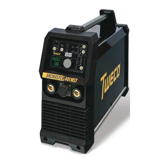
Page 36: Arcmaster 401Mst Power Source Controls, Indicators And Features
ARCMASTER 401MST POWER SOURCE 3.08 ArcMaster 401MST Power Source Controls, Indicators and Features Art # A-12452_AC Figure 3-2 INSTALLATION, OPERATION AND SETUP Manual 0-5287... - Page 37 ARCMASTER 401MST POWER SOURCE 1 VRD (Voltage Reduction Device) Indicator Lights A VRD (voltage reduction device) is a hazard reducing device designed to reduce electric shock hazards present on the output of welding power source when operating in SMAW (STICK) mode. Note that the presence of VRD should not be used as a substitute for the use of appropriate safety practices as indicated in section one of this manual.
- Page 38 ARCMASTER 401MST POWER SOURCE 6 Save/Load Buttons By using the Save & Load buttons the operator can easily save up to 10 welding parameter programs (including welding process, current/ voltage and other parameters such as arc force, inductance and hot start).
- Page 39 ARCMASTER 401MST POWER SOURCE 9 Contactor Control Local Control Remote Control Contactor Control either enables the weld output or assigns this function to a remote device. Refer to 3.14 Special Function for more info. 10 Positive Welding Terminal Welding current flows from the Power Source via heavy duty Dinse type terminal. It is essential, however, that the male plug is inserted and turned securely to achieve a sound electrical connection.
- Page 40 ARCMASTER 401MST POWER SOURCE 14 19 Pin Remote Control Socket The 19 pin Remote Control Socket is used to connect Remote Control devices or wire feeders that use a 19 pin connection to the welding Power Source. To make connections, align keyway, insert plug, and rotate threaded collar fully clockwise.
-
Page 41: Welding Parameters
ARCMASTER 401MST POWER SOURCE 3.09 Welding Parameters Parameter Description This parameter provides an adjustable short circuit current in STICK welding to improve electrode sticking and arc stability. Arc Force This parameter operates in STICK weld mode and is used to improve the start characteristics for stick electrodes. - Page 42 ARCMASTER 401MST POWER SOURCE Weld Process Selection Weld Mode LIFT Weld Parameter STICK Description WELD (V) Weld voltage MIG Mode. × √ × INDUCTANCE × √ × Inductance control in MIG Mode. HOT START Start current in amps is added or subtracted.
- Page 43 ARCMASTER 401MST POWER SOURCE In general, having the Arc Force set at 200% (maximum) allows greater penetration to be achieved. With the ARC set at 0% (minimum) the Power Source has a constant current characteristic. In other words, varying the arc length does not significantly affect the welding current.
-
Page 44: Setup For Lift Tig (Gtaw) Welding
ARCMASTER 401MST POWER SOURCE 3.10 Setup for LIFT TIG (GTAW) Welding For TIG welding a TIG torch with valve is required for this power source. A. Remove all packaging materials. Do not block the air vents at the front or rear of the Power Source. - Page 45 ARCMASTER 401MST POWER SOURCE Graphic for TIG Current Welding current Hot start current Short circuit Time Hot start Art # A-12456 Figure 3-5 TIG Current Routing Diagram Positive Welding Terminal (+) Work Lead Negative Welding Terminal (-) Art # A-12550...
-
Page 46: Setup For Stick (Smaw) Welding
ARCMASTER 401MST POWER SOURCE 3.11 Setup for STICK (SMAW) Welding A. Remove all packaging materials. Do not block the air vents at the front or rear of the Power Source. B. Connect the Electrode Holder to the positive welding terminal (+) (or negative welding terminal (-)). If in doubt, consult the electrode manufacturer. - Page 47 ARCMASTER 401MST POWER SOURCE Graphic for SMAW (STICK) Current Welding current Hot start current Time Hot start time Art # A-12457 Figure 3-7 STICK Current Routing Diagram Positive Welding Terminal (+) Electrode Holder Negative Welding Terminal (-) Work Lead Art # A-12551...
-
Page 48: Setup For Mig (Gmaw) Welding With Gas Shielded Mig Wire
ARCMASTER 401MST POWER SOURCE 3.12 Setup for MIG (GMAW) Welding with Gas Shielded MIG Wire A wire feeder (optional) is required for MIG welding. NOTE NOTE 1: The operations required may differ depending on the version and the configuration of the... - Page 49 ARCMASTER 401MST POWER SOURCE Positive Welding Terminal (+) ARCMASTER 401MST Negative Welding Terminal (-) Work Lead 19 Pin Control Socket Art # A-12552 Wirefeeder Tweco No. 4 MIG Torch Figure 3-9 Setup for MIG (GMAW) Welding with Gas Shielded MIG Wire...
-
Page 50: Setup For Fcaw Flux Core Arc Welding
ARCMASTER 401MST POWER SOURCE 3.13 Setup for FCAW Flux Core Arc Welding A wire feeder (optional) is required for MIG welding. NOTE NOTE 1: The operations required may differ depending on the version and the configuration of the wirefeeder! NOTE 2: Please read the wire feed operating manual! Power Source Connections A. - Page 51 ARCMASTER 401MST POWER SOURCE WIREFEEDER CONNECTIONS A. Connect the welding power cable to the negative welding terminal (-). If in doubt, consult the electrode wire manufacturer. Welding current flows from the Power Source via dinse type connectors. It is essential, however, that the male plug is inserted and turned securely to achieve a sound electrical connection.
-
Page 52: Special Function
ARCMASTER 401MST POWER SOURCE 3.14 Special Function Amphenol Selector Contactor Control Parameter Selection Button Remote Control Encoder Control Process Selection Button Art # A-12458_AB Figure 3-11 Gouging In Stick mode hold the Process Selection Button for 2 seconds and the LED will blink indicating Gouging mode is enabled. -
Page 53: Shielding Gas Flowmeter/ Regulator Operating Instructions
ARCMASTER 401MST POWER SOURCE 3.15 Shielding Gas Flowmeter/ Regulator Operating Instructions WARNING This equipment is designed for use with welding grade (Inert) shielding gases only. Shielding Gas Flowmeter/ Regulator Safety Designed to reduce and control high pressure gas from a cylinder or pipeline to the working pressure required for the equipment using it. - Page 54 ARCMASTER 401MST POWER SOURCE NOTE The flowmeter/ regulator used with argon based and carbon dioxide shielding gases are different. The flowmeter/ regulator supplied is for argon based shielding gases. If carbon dioxide is to be used a suitable carbon dioxide flowmeter/ regulator will need to be fitted.
- Page 55 ARCMASTER 401MST POWER SOURCE With the flowmeter/ regulator ready for operation, adjust working flow rate as follows: 1. Slowly turn adjusting screw/knob in (clockwise) direction until the outlet gauge indicates the required flow rate. NOTE It may be necessary to re-check the shielding gas flowmeter/ regulator flow rate following the first weld sequence due to back pressure present within shielding gas hose assembly.
- Page 56 ARCMASTER 401MST POWER SOURCE This Page Intentionally Blank INSTALLATION, OPERATION AND SETUP 3-26 Manual 0-5287...
-
Page 57: Section 4: Basic Welding Guide
Electrodes are generally connected to the ELECTRODE HOLDER with the Electrode Holder connected positive polarity. The WORK LEAD is connected negative polarity and is connected to the work piece. If in doubt consult the electrode data sheet or your nearest Accredited Tweco Distributor. Effects of Arc Welding Various Materials A. - Page 58 ARCMASTER 401MST POWER SOURCE Welding Position The electrodes dealt with in this publication can be used in most positions, i.e. they are suitable for welding in flat, horizontal, vertical and overhead positions. Numerous applications call for welds to be made in positions intermediate between these.
- Page 59 ARCMASTER 401MST POWER SOURCE Joint Preparations In many cases, it will be possible to weld steel sections without any special preparation. For heavier sections and for repair work on castings, etc., it will be necessary to cut or grind an angle between the pieces being joined to ensure proper penetration of the weld metal and to produce sound joints.
- Page 60 ARCMASTER 401MST POWER SOURCE clamp is making good electrical contact with the work, either directly or through the work table. For light gauge material, always clamp the work lead directly to the job, otherwise a poor circuit will probably result.
- Page 61 ARCMASTER 401MST POWER SOURCE Making Welded Joints Having attained some skill in the handling of an electrode, you will be ready to go on to make up welded joints. A. Butt Welds Set up two plates with their edges parallel, as shown in Figure 4-11, allowing 1/16" to 3/32" gap between them and tack weld at both ends.
- Page 62 ARCMASTER 401MST POWER SOURCE from the perpendicular position to prevent slag accumulate in the centre of the weld. Figure from running ahead of the weld. Refer to Figure 4-16 illustrates multi-run technique and Figure 4-13. Do not attempt to build up much larger than...
- Page 63 ARCMASTER 401MST POWER SOURCE 2. Vertical Down The tip of the electrode is held in light contact with the work and the speed of downward travel is regulated so that the tip of the electrode just keeps ahead of the slag. The electrode should point upwards at an angle of about 45º.
- Page 64 ARCMASTER 401MST POWER SOURCE not resume its former shape, and the contraction of the new shape exerts a strong pull on adjacent metal. Several things can then happen. The metal in the weld area is stretched (plastic deformation), the job may be pulled out of shape by the powerful contraction stresses (distortion), or the weld may crack, in any case, there will remain "locked-up"...
- Page 65 ARCMASTER 401MST POWER SOURCE Art # A-07707 Figure 4-21: Principle of Presetting Art # A-07428_AB Figure 4-26: Chain Intermittent Welding Art # A-07708 Art # A-07713_AB Preheat Preheat Weld Dotted lines show effect if no preheat is used Figure 4-22: Reduction of Distortion by Preheating...
-
Page 66: Stick (Smaw) Welding Troubleshooting
ARCMASTER 401MST POWER SOURCE 4.02 Stick (SMAW) Welding Troubleshooting FAULT CAUSE REMEDY 1 Welding current ARC FORCE parameter is Reduce the ARC FORCE parameter until welding fluctuations set at a value that causes current is reasonably constant while prohibit- the welding current to vary... - Page 67 ARCMASTER 401MST POWER SOURCE 4 A groove has been A Welding current is too A Reduce welding current. formed in the base high. metal adjacent to B Welding arc is too long. B Reduce the length of the welding arc.
-
Page 68: Tig (Gtaw) Basic Welding Technique
ARCMASTER 401MST POWER SOURCE 7 Crack occurring in A Rigidity of joint. A Redesign to relieve weld joint of severe stresses weld metal soon or use crack resistance electrodes. after solidification B Insufficient throat thick- B Travel slightly slower to allow greater build up in commences ness. - Page 69 ARCMASTER 401MST POWER SOURCE Tungsten Electrode Current Ranges Electrode Diameter DC Current (Amps) 0.040” (1.0mm) 30-60 1/16” (1.6mm) 60-115 3/32” (2.4mm) 100-165 1/8” (3.2mm) 135-200 5/32” (4.0mm) 190-280 3/16” (4.8mm) 250-340 Table 4-2: Current Ranges for Various Tungsten Electrode Sizes...
-
Page 70: Tig (Gtaw) Welding Problems
TIG Welding is generally regarded as a specialized process that requires operator competency. While many of the principles outlined in the previous Arc Welding section are applicable a comprehensive outline of the TIG Welding process is outside the scope of this Operating Manual. For further information please refer to www.tweco.com or contact Tweco. - Page 71 9 Arc start is not smooth. A Tungsten electrode is A Select the right size tungsten electrode. too large for the weld- Refer to Table 4-3 Tweco Tungsten Elec- ing current. trode Selection Chart. B The wrong electrode B Select the right tungsten electrode type.
- Page 72 ARCMASTER 401MST POWER SOURCE This Page Intentionally Blank BASIC WELDING GUIDE 4-16 Manual 0-5287...
-
Page 73: Section 5: Power Source Problems And Routine Service Requirements
If major complex subassemblies are faulty, then the Welding Power Source must be returned to an accredited Tweco Service Provider for repair. The basic level of troubleshooting is that which can be performed without special equipment or knowledge. Refer also to section 4 for solving welding problems. -
Page 74: Power Source Status Messages
There are extremely dangerous voltage and power levels present inside this Inverter Power Source. Do not attempt to open or repair unless you are an accredited Tweco Service Provider. Disconnect the Welding Power Source from the Mains Supply Voltage before disassembling. - Page 75 ARCMASTER 401MST POWER SOURCE Code Error Cause Possible Remedy E08-11 V/I Acquisition Voltage/current measuring Take to an accredited Tweco Service systems faulty Center for repair. E08-13 CAN Identification Unknown device connected Check connected devices and CAN connections Output Voltage Voltage measuring system Take to an accredited Tweco Service faulty.
-
Page 76: Routine Inspection, Testing & Maintenance
The inspection and testing of the power source and associated accessories shall be carried out by a licensed elec- trician. Safety in Welding and Allied Processes-Part 2 Electrical. This includes an insulation resistance test and an earthing test to ensure the integrity of the unit is compliant with Tweco original specifications. A. Testing Schedule 1. -
Page 77: Section 6: Key Spare Parts
ARCMASTER 401MST POWER SOURCE SECTION 6: KEY SPARE PARTS 6.01 401MST Power Source Spare Parts Art # A-12459 Figure 6-1 ArcMaster 401MST Spare Parts ArcMaster 401MST Spare Parts Item Description Des. Ref. Quantity Part Number Side Panel Left W7006700 Side Panel Right... - Page 78 Cooling Fan W7006742 Display Protection Cover W7006743 Label +/- Tweco W7006744 Label 401MST W7006745 Warning Sticker W7006746 Cover Plate (not shown) W7006747 Sticker Tweco 261 x 93 (not shown) W7006748 Table 6-1 ArcMaster 401MST Spart Parts KEY SPARE PARTS Manual 0-5287...
-
Page 79: Appendix A: Circuit Diagram
ARCMASTER 401MST POWER SOURCE APPENDIX A: CIRCUIT DIAGRAM MF-07 S00.0069.7 X7/2 X5/2 DMR05 X5/3 X5/4 X5/5 LP11 X7/1 X5/1 LP12 blue X1/4 X1/3 NEFI X1/2 X1/1 X2/1 X2/2 DRV02 X10/1 SF02 X10/2 X8/1 X8/2 X8/3 X2/1 X8/4 X2/2 X5/8 DC01... - Page 80 ARCMASTER 401MST POWER SOURCE This Page Intentionally Blank APPENDIX Manual 0-5287...
-
Page 81: Tweco - Limited Warranty Terms
“Purchaser” that its products will be free of defects in workmanship or material. Should any failure to conform to this warranty appear within the time period applicable to the Tweco products as stated below, Tweco shall, upon notification thereof and substantiation that the product has been stored, installed, oper- ated, and maintained in accordance with Tweco’s specifications, instructions, recommendations and recognized... - Page 82 This Page Intentionally Blank...
-
Page 83: Warranty Schedule
WARRANTY SCHEDULE 5 Years Parts* / 3 Years Labor ArcMaster, Excelarc, Fabricator, Fabstar, PowerMaster Portafeed, Ultrafeed, Ultima 150, WC 100B * 5 years on the Original Main Power Transformer and Inductors not mounted on PCBoards. * 3 years on Power Supply Components 2 Years Parts and Labor Unless specified Auto-Darkening Welding Helmet (electronic Lens), ** 1 Month Harness Assy Victor Regulator for Fabricator 141i (No labor) - Page 84 THE AMERICAS Denton, TX USA U.S. Customer Care Ph 1-800-426-1888 (tollfree) Fax: 1-800-535-0557 (tollfree) International Customer Care Ph 1-940-381-1212 Fax: 1-940-483-8178 Miami, FL USA Sales Office, Latin America Ph 1-954-727-8371 Fax: 1-954-727-8376 Oakville, Ontario, Canada Canada Customer Care Ph 1-905-827-4515 Fax: 1-800-588-1714 (tollfree) EUROPE Chorley, United Kingdom...
Need help?
Do you have a question about the ARCMASTER 401MST and is the answer not in the manual?
Questions and answers