Table of Contents
Advertisement
Quick Links
www.helivol.com
INSTRUCTION MANUAL
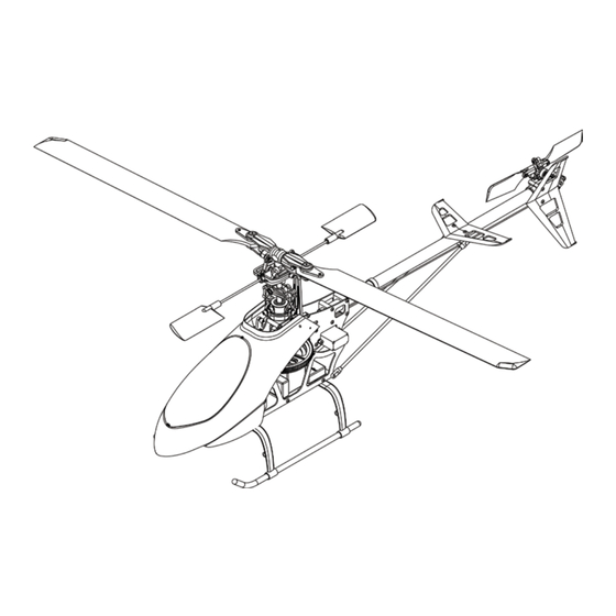
Specifications:
Length: 630mm
Height: 225mm
Main Rotor: 558mm
Tail Rotor: 150mm
Weight: 300g
Flying Weight 580-620g
Motor Gear: Variable
Main Gear: 138T
Hold Rotation Gear: 105T
Tail Gear: 1:9.85:5
PLEASE READ THROUGH THIS INSTRUCTION
MANUAL CAREFULLY. IT CONTAINS IMPOR-
TANT INSTRUCTIONS AND WARNINGS CON-
CERNING THE ASSEMBLY AND USE OF THIS
MODEL.
www.helivol.com
Advertisement
Table of Contents

Subscribe to Our Youtube Channel
Related Manuals for helivol Interceptor 400

Summary of Contents for helivol Interceptor 400
-
Page 1: Instruction Manual
INSTRUCTION MANUAL Specifications: Length: 630mm Height: 225mm Main Rotor: 558mm Tail Rotor: 150mm Weight: 300g Flying Weight 580-620g Motor Gear: Variable Main Gear: 138T Hold Rotation Gear: 105T Tail Gear: 1:9.85:5 PLEASE READ THROUGH THIS INSTRUCTION MANUAL CAREFULLY. IT CONTAINS IMPOR-... -
Page 2: Parts List
IntroductIon........2 The Interceptor 400 is an aerobatic capable helicopter, offering the performance and fly- EssEntIal EquIpmEnt.....3 ing abilities of 30 - sized nitro helicopter but within a smaller package. BuIld GuIdE........5-12 This is not a toy helicopter. It features a opEratIonal procEdurEs...13... - Page 3 Equipment needed: Motor Transmitter Electronic Speed Controller Tools: Receiver and Servos (3 Collective, 1 Tail) Pitch Gauge Blade Balancer Gyro Ball Link Pliers Cross Wrench Allen Wrench Philips Screwdriver Box Drive 4mm Battery and Charger...
-
Page 4: Radio Equipment
This will deliver the power needed to be used with an Alien command. They are get the most from the INTERCEPTOR 400 also a perfect fit for the frame. Please note but you can use any motor within the range that digital servos can not be used in con- 2800-3500kv with a suitable pinion. - Page 5 BuIld GuIdE: Measure the flybar so that is it equal on both sides of the head. Approx 60mm on The INTERCEPTOR 400 is a kit helicopter each side. this guide covers the INT-401 ARF. In this section we will take you through the process to ensure that you correctly assemble your model.
- Page 6 skIds Place the washer onto the collar of the Assemble skids - the uprights with the wider main gear. Insert the main shaft through the frame and into place. attachments points are located at the front. Screw the uprights into place and align the Place the main gear into the frame and push the shaft through - the washer should skid tubes.
- Page 7 Boom Align the hole on the end of the boom with the plastic pin inside the tail rotor assembly. You will need to feed the belt through the It will clip into place and hold firm. boom. Slide the tail push rod holder on to the We recommend taping the tail push rod to boom.
- Page 8 In order to easily place the belt over the Pull the boom back through and into place. gear it is recommended that you unscrew This should result in optimum belt tension. the bolt and screws on the boom holder. It To test the tension apply pressure onto one is then possible to push the boom further side of the belt.
-
Page 9: Installing The Motor
InstallInG tHE motor Cut out vertical tail fin decal and stick into place. Screw vertical tail fin onto tail mount. Attach a suitable pinion to motor shaft, use a drop of thread lock on the grub screw. Screw the motor into place on the helicop- ters frame - use a drop of thread lock on the mounting screws. -
Page 10: Installing Servos
Once your receiver is securely placed you can route your wires carefully across the frame of the INTERCEPTOR 400 ensur- ing that they clear of all moving parts and secured firmly with cable ties. The placing and wiring is dependent on the components you choose to use on your helicopter. - Page 11 Attach the servo arms to the elevator and aileron servos at 90° once their neutral points have been set. Then connect the push rods. At this point the swashplate should be completely flat. Consult the dia- gram on page 22. conFIGurInG sErVos Check that push rod lengths match the dia- gram on page 21.
- Page 12 7mm = ± 7° Pitch 8mm = ± 8° Pitch That completes the configuration and as- sembly of the INTERCEPTOR 400. Please follow guidelines for the individual compo- Fit the shield to the window with the screws nents regarding installation and setup. You supplied.
- Page 13 BEForE startInG a FlIGHt: parts lIst: modEls: 1. Pay attention to your surroundings: INT-400 INTERCEPTOR 400 KIT • Do not fly the helicopter in strong winds, INT-401 INTERCEPTOR 400 ARF rain or at night. sparEs: • Do not fly the helicopter near roads, rail- ways or electrical lines.
- Page 14 Elevator mount For an up to date and complete list of all of the upgrades INT-056 Flush head screw M2x15 please visit: INT-057 Collective pitch lever set (w/bearing) www.helivol.com INT-058 Servo mount INT-059 Aileron lever powEr EquIpmEnt: INT-060 Gyro mount...
- Page 15 INT-001 INT-002 INT-003 INT-004 INT-005 INT-009 INT-006 INT-008 INT-007 INT-010 INT-011 INT-012 INT-016 INT-013 INT-014 INT-015 INT-017 INT-018 INT-002 INT-001 INT-019 INT-020 Stabilizer blade and stabilizer control arm must be assembled so that they are parallel to one another INT-021...
- Page 16 (Int-023) INT-022 INT-002 INT-001 INT-024 INT-025 INT-026 INT-023 INT-031 INT-011 INT-029 INT-021 INT-028 INT-014 INT-027 INT-001 INT-002 INT-030 INT-015 INT-026 INT-027 INT-038 INT-024 INT-032 INT-039 INT-040 INT-033 INT-034 INT-036 INT-035 INT-041 INT-042 INT-043 INT-044 INT-025 INT-037...
- Page 17 INT-045 INT-044 INT-046 INT-047 INT-050 INT-048 INT-002 INT-001 INT-049 INT-038 INT-053 INT-039 INT-051 INT-052 INT-012 INT-012 INT-054 INT-055 INT-056 INT-012 INT-047 INT-032 INT-012 INT-057 INT-058 INT-047 INT-012 INT-002 INT-059 INT-024 INT-001 INT-066 INT-061 INT-067 INT-064 INT-066 INT-063 INT-064 INT-044 INT-012 INT-060 INT-065 INT-012...
- Page 18 INT-068 INT-052 INT-066 INT-052 INT-047 INT-047 INT-069 INT-069 Balance the main rotor blade. Stick tracking tape onto the lighter of the two blades to compensate the weight difference. INT-070...
- Page 19 INT- INT-014 INT-074 INT-072 INT-071 INT-075 INT-076 INT-078 INT-034 INT-079 INT-080 INT-077 INT-081 INT-083 INT-082 INT-085 INT-084...
- Page 20 INT-086 INT-087 INT-088 INT-089 INT-090 INT-091 INT-092 INT-085 INT-086 INT-087 INT-088 INT-093...
- Page 21 INT-090 INT-092 INT-091 INT-089...
- Page 22 INT-095 INT-094...
-
Page 23: Warranty
HELIVOL guarantees this kit to be free from de- As HELIVOL has no control over use, setup, fects in both material and workmanship at the final assembly, modification or misuse, no li- date of purchase. This warranty does not cover... - Page 24 Helivol © Copyright 2009 MADE IN TAIWAN www.helivol.com...
Need help?
Do you have a question about the Interceptor 400 and is the answer not in the manual?
Questions and answers