Sony HCD-EC69i Service Manual
Hide thumbs
Also See for HCD-EC69i:
- Operating instructions (2 pages) ,
- Service manual (68 pages) ,
- Service manual (68 pages)
Table of Contents
Advertisement
HCD-EC69i/EC79i/EC99i
QQ
3 7 63 1515 0
SERVICE MANUAL
Ver. 1.1 2009.05
• HCD-EC69i is the amplifi er, CD player, tuner
and iPod section in MHC-EC69i.
• HCD-EC79i is the amplifi er, CD player, tuner
and iPod section in MHC-EC79i.
• HCD-EC99i is the amplifi er, CD player, tuner
and iPod section in MHC-EC99i.
iPod is a trademark of Apple Inc., registered in the U.S.
and other countries.
MPEG Layer-3 audio coding technology and patents
licensed from Fraunhofer IIS and Thomson.
All other trademarks and registered trademarks are of
their respective holders. In this manual,
are not specified.
TE
L 13942296513
Main unit
AUDIO POWER SPECIFICATIONS
POWER OUTPUT AND TOTAL HARMONIC DISTORTION:
(HCD-EC99i, HCD-EC79i The United States model only)
Low channel
With 8 ohm loads, both channels driven, from 120 – 10,000 Hz; rated 60 watts
per channel minimum RMS power, with no more than 0.7% total harmonic
distortion from 250 milliwatts to rated output.
High channel
With 8 ohm loads, both channels driven, from 2,000 – 13,000 Hz; rated
60 watts per channel minimum RMS power, with no more than 0.7% total
harmonic distortion from 250 milliwatts to rated output.
AUDIO POWER SPECIFICATIONS
POWER OUTPUT AND TOTAL HARMONIC DISTORTION:
(HCD-EC69i The United States model only)
With 6 ohm loads, both channels driven, from 120 – 10,000 Hz; 30 watts
per channel minimum RMS power, with no more than 0.7% total harmonic
distortion from 250 milliwatts to rated output.
Amplifier section
HCD-EC99i
Front Speaker
RMS output power (reference):
Low channel
95 W + 95 W (per channel at 8 Ω, 1 kHz, 10% THD)
High channel
95 W + 95 W (per channel at 8 Ω, 8 kHz, 10% THD)
Subwoofer
RMS output power (reference):
150 W (at 4 Ω, 80 Hz, 10% THD)
HCD-EC79i
RMS output power (reference):
Low channel
95 W + 95 W (per channel at 8 Ω, 1 kHz, 10% THD)
High channel
95 W + 95 W (per channel at 8 Ω, 8 kHz, 10% THD)
HCD-EC69i
RMS output power (reference):
50 W + 50 W (per channel at 6 Ω, 1 kHz, 10% THD)
Inputs (except for HCD-EC69i)
PC IN (stereo mini jack): Sensitivity 800 mV, impedance 22 kilohms
Outputs
PHONES (stereo mini jack): Accepts headphones with an impedance of 8 Ω
or more
SPEAKER: impedance
HCD-EC99i/EC79i: 8 Ω
HCD-EC69i: 6 Ω
SUBWOOFER OUT (HCD-EC99i only): impedance 4 Ω
www
.
Sony Corporation
9-889-427-02
2009E05-1
Audio&Video Business Group
©
2009.05
Published by Sony Techno Create Corporation
http://www.xiaoyu163.com
Model Name Using Similar Mechanism
Mechanism Type
®
TM
and
marks
Base Unit Name
Optical Pick-up Block Name
CD player section
System: Compact disc and digital audio system
Laser Diode Properties
Emission Duration: Continuous
Laser Output*: Less than 44.6μW
* This output is the value measurement at a distance of 200mm from the
objective lens surface on the Optical Pick-up Block with 7mm aperture.
Frequency response: 20 Hz 20 kHz
Signal-to-noise ratio: More than 90 dB
Dynamic range: More than 88 dB
Tuner section
FM stereo, FM/AM superheterodyne tuner
Antenna:
FM lead antenna
AM loop antenna
FM tuner section:
Tuning range
North American model: 87.5 108.0 MHz (100 kHz step)
Other models: 87.5 108.0 MHz (50 kHz step)
Intermediate frequency: 10.7 MHz
AM tuner section:
Tuning range
North American model:
530 1,710 kHz (with 10 kHz tuning interval)
531 1,710 kHz (with 9 kHz tuning interval)
Australian model:
531 1,710 kHz (with 9 kHz tuning interval)
530 1,710 kHz (with 10 kHz tuning interval)
UK model:
531 1,602 kHz (with 9 kHz tuning interval)
Intermediate frequency: 450 kHz
x
ao
u163
y
i
http://www.xiaoyu163.com
2 9
8
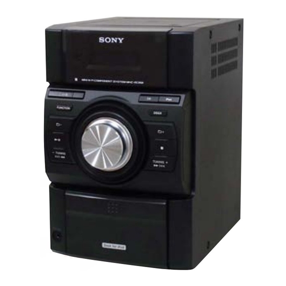
Photo: HCD-EC69i
CDM76A-K6BD90-WOD
EC79i: UK, Australian/EC99i
EC69i/EC79i: US, Canadian
EC79i: UK, Australian/EC99i
EC69i/EC79i: US, Canadian
EC79i: UK, Australian/EC99i
Q Q
3
6 7
1 3
1 5
SPECIFICATIONS
iPod section
Compatible iPod models:
iPod nano 4th
iPod touch 2nd
generation
(video)
generation
iPod nano 3rd
generation
iPod classic
(video)
iPod nano 1st
iPod 5th
generation
generation
(video)
iPod mini
iPod 4th
generation
COMPACT DISC RECEIVER
co
.
9 4
2 8
US Model
Canadian Model
UK Model
Australian Model
NEW
CDM76A-K6BD90-WOD
BU-K8BD90-WOD
BU-K6BD90-WOD
KSM-213CDP
KSM-213DCP
0 5
8
2 9
9 4
2 8
General
Power requirements:
North American model: AC 120 V, 60 Hz
Australian model: AC 230 240 V, 50/60 Hz
UK model: AC 230 V, 50/60 Hz
Power consumption:
HCD-EC99i
250 W
(0.5 W at the Power Saving Mode)
HCD-EC79i
200 W
iPod touch 1st
(0.5 W at the Power Saving Mode)
generation
HCD-EC69i
80 W
(0.5 W at the Power Saving Mode)
Dimensions (w/h/d) (excl. speakers):
HCD-EC99i
Approx. 200 × 311 × 375 mm
HCD-EC79i (Australian and UK models only)
Approx. 200 × 311 × 375 mm
iPod nano 2nd
HCD-EC79i (North American model only)
generation
Approx. 200 × 306 × 375 mm
(aluminum)
HCD-EC69i
Approx. 200 × 306 × 305 mm
Mass (excl. speakers):
HCD-EC99i
Approx. 6.2 kg
HCD-EC79i (Australian and UK models only)
Approx. 6.0 kg
HCD-EC79i (North American model only)
Approx. 5.7 kg
iPod 4th
HCD-EC69i
generation
Approx. 3.8 kg
(color display)
Design and specifications are subject to change without notice.
m
9 9
9 9
Advertisement
Table of Contents

Related Manuals for Sony HCD-EC69i


Summary of Contents for Sony HCD-EC69i
-
Page 1: Service Manual
Canadian Model Ver. 1.1 2009.05 UK Model Australian Model • HCD-EC69i is the amplifi er, CD player, tuner and iPod section in MHC-EC69i. • HCD-EC79i is the amplifi er, CD player, tuner and iPod section in MHC-EC79i. • HCD-EC99i is the amplifi er, CD player, tuner and iPod section in MHC-EC99i. - Page 2 LES DIAGRAMMES SCHÉMATIQUES ET LA LISTE DES PIÈCES SONT CRITIQUES POUR LA SÉCURITÉ DE FONC- TIONNEMENT. NE REMPLACER CES COMPOSANTS QUE PAR DES PIÈCES SONY DONT LES NUMÉROS SONT DON- NÉS DANS CE MANUEL OU DANS LES SUPPLÉMENTS PUBLIÉS PAR SONY.
-
Page 3: Table Of Contents
3-11. Top Panel Block 7-2. Overall Section (HCD-EC79i/EC99i) ......47 (HCD-EC79i: UK, Australian/EC99i) ......15 7-3. Top Panel Section (HCD-EC69i/EC79i: US, CND) ..48 3-12. CD Mechanism Deck (CDM76A-K6BD90-WOD) 7-4. Top Panel Section (HCD-EC79i: UK, AUS/EC99i) ..49 (HCD-EC79i: UK, Australian/EC99i) ......15 7-5. -
Page 4: Servicing Notes
HCD-EC69i/EC79i/EC99i Ver. 1.1 SECTION 1 SERVICING NOTES 3 7 63 1515 0 MODEL IDENTIFICATION NOTES ON HANDLING THE OPTICAL PICK-UP - Back Panel - BLOCK OR BASE UNIT The laser diode in the optical pick-up block may suffer electro-... - Page 5 HCD-EC69i/EC79i/EC99i 3 7 63 1515 0 HOW TO REMOVE THE KNOB (VOL) knob (VOL) front panel block (back view) hole Push the knob (VOL) by flat-head screwdriver. L 13942296513 CAPACITOR DISCHARGE FOR ELECTRIC SHOCK PREVENTION Note: Please take out the top panel block and side panel (L/R) from a set refer to DISASSEMBLY (from Page 10).
- Page 6 HCD-EC69i/EC79i/EC99i 3 7 63 1515 0 HOW TO OPEN THE TRAY WHEN POWER SWITCH TURN OFF (HCD-EC79i: UK, Australian/EC99i only) Note: Please take out the top panel block from a set refer to DISASSEMBLY (from Page 15). top panel block...
-
Page 7: General
To use the remote Slide and remove the battery compartment lid, and insert the two R6 (size AA) batteries (supplied, except for HCD-EC69i), side first, matching the polarities shown below. Notes on using the remote With normal use, the batteries should last for about six months. - Page 8 To use an iPod, refer to the user’s guide of your iPod. The system offers the following display modes. Sony cannot accept responsibility in the event that data recorded to iPod is lost or damaged when using an iPod with this unit.
-
Page 9: Disassembly
DISASSEMBLY 3 7 63 1515 0 • This set can be disassembled in the order shown below. 3-1. DISASSEMBLY FLOW • HCD-EC69i/EC79i: US, Canadian ORNAMENT PLATE (DOCK) OR iPod ASSY (Page 11) 3-2. SIDE PANEL (L)/(R) BASE (DOCK) (Page 10) (Page 12) 3-3. -
Page 10: Side Panel (L)/(R) (Hcd-Ec69I/Ec79I: Us, Canadian)
HCD-EC69i/EC79i/EC99i 3 7 63 1515 0 Note: Follow the disassembly procedure in the numerical order given. 3-2. SIDE PANEL (L)/(R) (HCD-EC69i/EC79i: US, Canadian) 3 two claws 2 two screws (BVTP3 3 two claws 1 three screws (case3 TP2) 2 two screws... -
Page 11: Ornament Plate (Dock) Or Ipod Assy
HCD-EC69i/EC79i/EC99i 3 7 63 1515 0 3-4. ORNAMENT PLATE (DOCK) OR iPod ASSY Note: This illustration sees the front panel from bottom side. Press the iPod dock in the direction of arrow four claws Push the gap by the flat-head screwdriver. -
Page 12: Base (Dock)
(B2.6) Left up the IP board. boss base (dock) boss L 13942296513 3-6. MAIN BOARD (HCD-EC69i/EC79i: US, Canadian) connector (EC69i: CN102, EC79i: CN101) fan motor connector (CN601) MAIN board two screws (BVTP3 × 10) two screws (BVTP3 × 10) -
Page 13: Front Panel Block (Hcd-Ec69I/Ec79I: Us, Canadian)
HCD-EC69i/EC79i/EC99i 3 7 63 1515 0 3-7. FRONT PANEL BLOCK (HCD-EC69i/EC79i: US, Canadian) 1 flexible flat cable (25 core) (CN607) 2 flexible flat cable (11 core) 5 front panel block (CN653) 3 flexible flat cable (7 core) (EC69i: CN606),... -
Page 14: Optical Pick-Up Block (Ksm-213Cdp) (Hcd-Ec69I/Ec79I: Us, Canadian)
HCD-EC69i/EC79i/EC99i 3 7 63 1515 0 3-9. OPTICAL PICK-UP BLOCK (KSM-213CDP) (HCD-EC69i/EC79i: US, Canadian) optical pick-up block (KSM-213CDP) wire (flat type) (16 core) (optical pick-up, CD board: CN201) CD board Remove the four solders. L 13942296513 3-10. SIDE PANEL (L)/(R) -
Page 15: Top Panel Block (Hcd-Ec79I: Uk, Australian/Ec99I)
HCD-EC69i/EC79i/EC99i 3 7 63 1515 0 3-11. TOP PANEL BLOCK (HCD-EC79i: UK, Australian/EC99i) two claws two screws (BVTP3 × 10) top panel block flexible flat cable (5 core) (CN302) screw (BVTP3 × 10) screw (KTP3 × 10) flexible flat cable (21 core) -
Page 16: Main Board (Hcd-Ec79I: Uk, Australian/Ec99I)
HCD-EC69i/EC79i/EC99i 3 7 63 1515 0 3-13. MAIN BOARD (HCD-EC79i: UK, Australian/EC99i) fan motor connector (CN601) bracket (PWB) MAIN board flexible flat cable (5 core) (CN603) flexible flat cable (7 core) screw (EC99i: CN643) (BVTP3 × 10) (EC99i) two screws (BVTP3 ×... -
Page 17: Base Unit (Bu-K6Bd90-Wod)
HCD-EC69i/EC79i/EC99i 3 7 63 1515 0 3-15. BASE UNIT (BU-K6BD90-WOD) (HCD-EC79i: UK, Australian/EC99i) Note: This illustration sees the base unit from CD board side. two coil springs (insulator) four screws (PTPWH M2.6) two coil springs (insulator) two insulators base unit... -
Page 18: Belt (Cdm76) (Hcd-Ec79I: Uk, Australian/Ec99I)
HCD-EC69i/EC79i/EC99i 3 7 63 1515 0 3-17. BELT (CDM76) (HCD-EC79i: UK, Australian/EC99i) belt (CDM76) Draw out the tray. bracket Push hard the bracket by tray the flat-head screwdriver. L 13942296513 flat-head screwdriver bracket – CD mechanism deck (front view) –... -
Page 19: Test Mode
HCD-EC69i/EC79i/EC99i Ver. 1.1 SECTION 4 TEST MODE 3 7 63 1515 0 COLD RESET CD TRAY LOCK (EC79i: UK, Australian/EC99i) The cold reset clears all data including preset data stored in the This mode is for the antitheft of CD disc in shop. (not for transport) Procedure: memory to initial conditions. - Page 20 HCD-EC69i/EC79i/EC99i 3 7 63 1515 0 CD SERVO TEST MODE CD Servo Test Mode Tree: This mode can check the servo system operations of the optical Higher layer Lower layer of menu hierarchy S Curve Mode LD ON pick-up system (= optical unit + CD board).
- Page 21 HCD-EC69i/EC79i/EC99i 3 7 63 1515 0 CD SERVICE MODE 2 It indicates the error content This mode can move the SLED of the optical pick-up, and also can 01: The focus servo cannot lock-in. turn the optical pick-up laser power on and off.
- Page 22 HCD-EC69i/EC79i/EC99i 3 7 63 1515 0 CD FACTORY MODE Note 1: Do not enter the this mode while any other test mode is in prog- ress. Note 2: Do not enter any other test mode while the this mode is in prog- ress.
-
Page 23: Electrical Adjustments
HCD-EC69i/EC79i/EC99i Ver. 1.1 SECTION 5 ELECTRICAL ADJUSTMENTS 3 7 6 3 1 5 1 5 0 Adjustment Location and Connecting Points: CD SECTION TUNER SECTION 0 dB = 1 μV FM FREQUENCY COVERAGE ADJUSTMENT Reading on Digital Adjustment Part Frequency Display –... -
Page 24: Diagrams
HCD-EC69i/EC79i/EC99i SECTION 6 DIAGRAMS 3 7 6 3 1 5 1 5 0 6-1. BLOCK DIAGRAM - CD, TUNER Section - CN801 ANTENNA FM/AM BAND-PASS FILTER 36 FM RF-IN FM-MIX 8 FM IF-IN FM DET-OUT 22 MPX-IN L-OUT TUNER-L... -
Page 25: Block Diagram - Main Section
HCD-EC69i/EC79i/EC99i 3 7 6 3 1 5 1 5 0 6-2. BLOCK DIAGRAM - MAIN Section - (EC69i) POWER R-ch is omitted due to same as L-ch. SIGNAL PATH IC102 : TUNER (FM/AM) : CD PLAY (EC79i) : iPod... -
Page 26: Block Diagram - Panel, Power Supply Section
HCD-EC69i/EC79i/EC99i Ver. 1.1 3 7 6 3 1 5 1 5 0 6-3. BLOCK DIAGRAM - PANEL, POWER SUPPLY Section - SP-L D601 R-CH FAN MOTOR PROTECT DRIVE DETECT Q601, 602 Q607 D602, 606 (Page 25) OVER LOAD DETECT... - Page 27 HCD-EC69i/EC79i/EC99i 3 7 6 3 1 5 1 5 0 THIS NOTE IS COMMON FOR PRINTED WIRING BOARDS AND SCHEMATIC DIAGRAMS. • Circuit Boards Location (In addition to this, the necessary note is printed in each block.) For Printed Wiring Boards.
-
Page 28: Printed Wiring Board - Cd Board
HCD-EC69i/EC79i/EC99i 3 7 6 3 1 5 1 5 0 6-4. PRINTED WIRING BOARD - CD Board - • See page 27 for Circuit Boards Location. • : Uses unleaded solder. CD BOARD (CONDUCTOR SIDE) CD BOARD (COMPONENT SIDE) -
Page 29: Schematic Diagram - Cd Board
HCD-EC69i/EC79i/EC99i 3 7 6 3 1 5 1 5 0 6-5. SCHEMATIC DIAGRAM - CD Board - • See page 40 for Waveforms. • See page 40 for IC Block Diagrams. • See page 42 for IC Pin Function Description. -
Page 30: Schematic Diagram - Main Board (1/2)
HCD-EC69i/EC79i/EC99i Ver. 1.1 3 7 6 3 1 5 1 5 0 6-6. SCHEMATIC DIAGRAM - MAIN Board (1/2) - • See page 40 for Waveforms. • See page 40 for IC Block Diagrams. MAIN BOARD (1/2) D801 C851... -
Page 31: Schematic Diagram - Main Board (2/2)
HCD-EC69i/EC79i/EC99i 3 7 6 3 1 5 1 5 0 6-7. SCHEMATIC DIAGRAM - MAIN Board (2/2) - • See page 40 for IC Block Diagrams. MAIN BOARD (2/2) MAIN BOARD (1/2) (Page 30) MAIN R672 BOARD (1/2) R746... -
Page 32: Printed Wiring Board - Main Board
HCD-EC69i/EC79i/EC99i 3 7 6 3 1 5 1 5 0 6-8. PRINTED WIRING BOARD - MAIN Board - • See page 27 for Circuit Boards Location. • : Uses unleaded solder. • Semiconductor Location Ref. No. Location (EC99i) (Page 33) -
Page 33: Printed Wiring Boards - Amp Section
HCD-EC69i/EC79i/EC99i 3 7 6 3 1 5 1 5 0 6-9. PRINTED WIRING BOARDS - AMP Section - • See page 27 for Circuit Boards Location. • : Uses unleaded solder. • Semiconductor Location Ref. No. Location D140 D141... -
Page 34: 6-10. Schematic Diagram - 2Ch-4Ch Amp Board
HCD-EC69i/EC79i/EC99i 3 7 6 3 1 5 1 5 0 6-10. SCHEMATIC DIAGRAM - 2CH-4CH AMP Board - 2CH-4CH AMP BOARD (EC99i) (EC79i) (EC69i) IC103 IC102 IC101 STK433-090-E STK433-890-E +PRE SUB GND STK433-040 +PRE SUB GND +PRE SUB GND... -
Page 35: Schematic Diagram - 3Ch Amp Board (Ec99I)
HCD-EC69i/EC79i/EC99i 3 7 6 3 1 5 1 5 0 6-11. SCHEMATIC DIAGRAM - 3CH AMP Board (EC99i) - 3CH AMP BOARD IC201 POWER AMP IC201 STK433-330-E +PRE SUB GND D202 Q201 - 203 MA2J1110GLS0 OVER LOAD DETECT R240... -
Page 36: 6-12. Printed Wiring Boards - Panel Section
HCD-EC69i/EC79i/EC99i Ver. 1.1 3 7 6 3 1 5 1 5 0 6-12. PRINTED WIRING BOARDS - PANEL Section - • See page 27 for Circuit Boards Location. • : Uses unleaded solder. • Semiconductor Location Ref. No. Location... -
Page 37: 6-13. Schematic Diagram - Panel Section
HCD-EC69i/EC79i/EC99i Ver. 1.1 3 7 6 3 1 5 1 5 0 6-13. SCHEMATIC DIAGRAM - PANEL Section - • See page 40 for Waveforms. • See page 40 for IC Block Diagrams. • See page 42 for IC Pin Function Description. -
Page 38: 6-14. Printed Wiring Boards - Audio In/Out, Key, Power Supply Section
HCD-EC69i/EC79i/EC99i Ver. 1.1 3 7 6 3 1 5 1 5 0 6-14. PRINTED WIRING BOARDS - AUDIO IN/OUT, KEY, POWER SUPPLY Section - • See page 27 for Circuit Boards Location. • : Uses unleaded solder. • Semiconductor Location Ref. -
Page 39: 6-15. Schematic Diagram - Audio In/Out, Key, Power Supply Section
HCD-EC69i/EC79i/EC99i Ver. 1.1 3 7 6 3 1 5 1 5 0 6-15. SCHEMATIC DIAGRAM - AUDIO IN/OUT, KEY, POWER SUPPLY Section - REG BOARD KEY BOARD PT-SINGLE BOARD (EC79i: UK, AUS/EC99i) IC601 R408 R407 R406 R405 R404 3.9k 2.7k... - Page 40 HCD-EC69i/EC79i/EC99i 3 7 6 3 1 5 1 5 0 • Waveforms – MAIN Board – IC602 BD3499FV-E2 – CD Board – – MAIN Board – – PANEL Board – IC101 (RFi) IC801 (XOUT) IC301 (X1A) (CD play mode)
- Page 41 HCD-EC69i/EC79i/EC99i 3 7 63 1515 0 IC801 LV23003VA AM RF-IN 36 FM RF-IN 35 GND2 34 FMRF-OUT 33 VCC2 FM-MIX 32 FM-OSC GND1 AM-MIX 31 AM-OSC VCC1 30 BO2 29 BO1 BUFFER LOW-PASS 28 LP-OUT FILTER 27 LP-IN 26 PD...
- Page 42 HCD-EC69i/EC79i/EC99i 3 7 63 1515 0 • IC Pin Function Description CD BOARD IC101 TC94A70FG-006 (CD-MP3 PROCESSOR) Pin No. Pin Name Description AVSS3 Ground terminal RFZi RF ripple zero crossing signal input terminal RFRP RF ripple signal output terminal...
- Page 43 HCD-EC69i/EC79i/EC99i 3 7 63 1515 0 Pin No. Pin Name Description Not used SFSY/LOCK Not used ZDET Zero detection signal output terminal Not used GPIN Not used Microcomputer interface mode selection signal input terminal Fixed at “H” in this set...
- Page 44 HCD-EC69i/EC79i/EC99i 3 7 63 1515 0 PANEL BOARD IC301 MB90F830PF-GE1 (SYSTEM CONTROLLER) Pin No. Pin Name Description SEG32 Segment drive signal output to the liquid crystal display O-SP-RELAY-ON/ Relay drive signal output terminal (for speaker), and subwoofer function on/off control signal...
- Page 45 HCD-EC69i/EC79i/EC99i 3 7 63 1515 0 Pin No. Pin Name Description COM0, COM1, 59 to 62 Common drive signal output to the liquid crystal display CMO2, CMO3 63, 64 SEG0, SEG1 Segment drive signal output to the liquid crystal display Power supply terminal (+3.3V)
-
Page 46: Exploded Views
• Abbreviation le numéro spécifi é. : Australian model CND : Canadian model 7-1. OVERALL SECTION (HCD-EC69i) top panel section (HCD-EC69i/EC79i: US, CND) L 13942296513 not supplied MAIN boad, chassis section (HCD-EC69i) front panel section Ref. No. Part No. Description Remark Ref. -
Page 47: Overall Section (Hcd-Ec79I/Ec99I)
3 7 63 1515 0 7-2. OVERALL SECTION (HCD-EC79i/EC99i) (EC79i: US, CND) (EC79i: UK, AUS/EC99i) top panel section top panel section (HCD-EC79i: UK, AUS/EC99i) (HCD-EC69i/EC79i: US, CND) L 13942296513 (EC79i: US, CND) not supplied MAIN boad section (HCD-EC79i/EC99i) front panel section Ref. No. -
Page 48: Top Panel Section (Hcd-Ec69I/Ec79I: Us, Cnd)
HCD-EC69i/EC79i/EC99i 3 7 63 1515 0 7-3. TOP PANEL SECTION (HCD-EC69i/EC79i: US, CND) not supplied (EC69i) (ES79i: US, CND) included in included in SW750 SW750 L 13942296513 (including sled motor (M402), spindle motor (M401)) included in (sled motor (M402)) -
Page 49: Top Panel Section (Hcd-Ec79I: Uk, Aus/Ec99I)
HCD-EC69i/EC79i/EC99i Ver. 1.1 3 7 63 1515 0 7-4. TOP PANEL SECTION (HCD-EC79i: UK, AUS/EC99i) not supplied not supplied (LOADING board) (including sled motor (M402), spidle motor (M401)) L 13942296513 included in included in (spindle motor (M401)) (sled motor (M402)) S201 Ref. -
Page 50: Front Panel Section
HCD-EC69i/EC79i/EC99i Ver. 1.1 3 7 63 1515 0 7-5. FRONT PANEL SECTION not supplied (JACK HOLD board) not supplied (JACK board) not supplied (EC79i: UK, AUS/EC99i) not supplied not supplied (KEY board) (FFC HOLD board) (EC79i/E99i) not supplied (COVER board) -
Page 51: Ipod Dock Section
HCD-EC69i/EC79i/EC99i 3 7 63 1515 0 7-6. iPod DOCK SECTION not supplied (IP board) L 13942296513 Ref. No. Part No. Description Remark Ref. No. Part No. Description Remark X-2348-584-1 IPOD ASSY (EC79i/EC99i) 1-836-763-21 CABLE, FLEXIBLE FLAT (11 CORE) (EC79i/EC99i) -
Page 52: Main Board, Chassis Section (Hcd-Ec69I)
HCD-EC69i/EC79i/EC99i 3 7 63 1515 0 7-7. MAIN BOARD, CHASSIS SECTION (HCD-EC69i) M601 not supplied not supplied (REG board) not supplied not supplied (AC HOLD board) PT004 L 13942296513 not supplied (2CH-4CH board) supplied not supplied (PT-SINGLE board) not supplied... -
Page 53: Main Board Section (Hcd-Ec79I/Ec99I)
HCD-EC69i/EC79i/EC99i Ver. 1.1 3 7 63 1515 0 7-8. MAIN BOARD SECTION (HCD-EC79i/EC99i) (EC99i) M601 not supplied (AC HOLD board) L 13942296513 chassis section chassis section (EC99i) (EC79i) Ref. No. Part No. Description Remark Ref. No. Part No. Description... -
Page 54: Chassis Section (Hcd-Ec79I/Ec99I)
HCD-EC69i/EC79i/EC99i Ver. 1.1 3 7 63 1515 0 7-9. CHASSIS SECTION (HCD-EC79i/EC99i) (EC99i) (EC79i) not supplied not supplied (2CH-4CH AMP board) supplied not supplied (2CH-4CH not supplied AMP board) (REG board) not supplied (3CH AMP board) not supplied not supplied... -
Page 55: Electrical Parts List
HCD-EC69i/EC79i/EC99i SECTION 8 2CH-4CH AMP ELECTRICAL PARTS LIST 3 7 63 1515 0 Note: • Due to standardization, replacements in • CAPACITORS When indicating parts by reference num- the parts list may be different from the uF: μF ber, please include the board name. - Page 56 HCD-EC69i/EC79i/EC99i 2CH-4CH AMP 3CH AMP 3 7 63 1515 0 Ref. No. Part No. Description Remark Ref. No. Part No. Description Remark < RESISTOR > R144 1-216-837-11 METAL CHIP 1/10W R103 1-216-820-11 METAL CHIP 1/10W R145 1-216-825-11 METAL CHIP 2.2K...
- Page 57 HCD-EC69i/EC79i/EC99i 3CH AMP 3 7 63 1515 0 Ref. No. Part No. Description Remark Ref. No. Part No. Description Remark < CONNECTOR > R245 1-216-817-11 METAL CHIP 1/10W R246 1-216-817-11 METAL CHIP 1/10W CN203 1-568-826-11 CONNECTOR, FFC 7P ************************************************************...
- Page 58 HCD-EC69i/EC79i/EC99i 3 7 63 1515 0 Ref. No. Part No. Description Remark Ref. No. Part No. Description Remark C301 1-164-360-11 CERAMIC CHIP 0.1uF R154 1-216-857-11 METAL CHIP 1/10W C302 1-137-710-91 CERAMIC CHIP 10uF 6.3V R155 1-216-805-11 METAL CHIP 1/10W...
- Page 59 HCD-EC69i/EC79i/EC99i Ver. 1.1 JACK LOADING MAIN 3 7 63 1515 0 Ref. No. Part No. Description Remark Ref. No. Part No. Description Remark R905 1-218-895-11 METAL CHIP 100K 0.5% 1/10W SW325 1-771-410-21 SWITCH, TACTILE (DSGX) R906 1-218-895-11 METAL CHIP 100K 0.5%...
- Page 60 HCD-EC69i/EC79i/EC99i Ver. 1.1 MAIN 3 7 63 1515 0 Ref. No. Part No. Description Remark Ref. No. Part No. Description Remark C630 1-126-947-11 ELECT 47uF C705 1-126-964-11 ELECT 10uF C631 1-126-933-11 ELECT 100uF (EC99i) C632 1-126-963-11 ELECT 4.7uF C633 1-165-176-11 CERAMIC CHIP 0.047uF...
- Page 61 HCD-EC69i/EC79i/EC99i MAIN 3 7 63 1515 0 Ref. No. Part No. Description Remark Ref. No. Part No. Description Remark C831 1-117-863-11 CERAMIC CHIP 0.47uF 6.3V D627 8-719-062-51 DIODE 1PS226-115 D628 6-501-817-01 DIODE MA2J1110GLS0 C832 1-117-863-11 CERAMIC CHIP 0.47uF 6.3V...
- Page 62 HCD-EC69i/EC79i/EC99i MAIN 3 7 63 1515 0 Ref. No. Part No. Description Remark Ref. No. Part No. Description Remark Q603 8-729-120-28 TRANSISTOR 2SC1623-L5L6 R626 1-216-833-11 METAL CHIP 1/10W Q604 8-729-120-28 TRANSISTOR 2SC1623-L5L6 R627 1-216-829-11 METAL CHIP 4.7K 1/10W R628...
- Page 63 HCD-EC69i/EC79i/EC99i MAIN 3 7 63 1515 0 Ref. No. Part No. Description Remark Ref. No. Part No. Description Remark R681 1-216-837-11 METAL CHIP 1/10W R742 1-216-789-11 METAL CHIP 1/10W R684 1-216-837-11 METAL CHIP 1/10W R685 1-216-829-11 METAL CHIP 4.7K...
- Page 64 HCD-EC69i/EC79i/EC99i Ver. 1.1 MAIN PANEL 3 7 63 1515 0 Ref. No. Part No. Description Remark Ref. No. Part No. Description Remark R797 1-216-841-11 METAL CHIP 1/10W R798 1-216-829-11 METAL CHIP 4.7K 1/10W R868 1-216-823-11 METAL CHIP 1.5K 1/10W...
- Page 65 HCD-EC69i/EC79i/EC99i Ver. 1.1 PANEL 3 7 63 1515 0 Ref. No. Part No. Description Remark Ref. No. Part No. Description Remark C303 1-126-964-11 ELECT 10uF < IC > C304 1-100-597-91 CERAMIC CHIP 0.1uF C305 1-126-964-11 ELECT 10uF IC301 A-1711-704-A...
- Page 66 HCD-EC69i/EC79i/EC99i Ver. 1.1 PANEL PT-SINGLE 3 7 63 1515 0 Ref. No. Part No. Description Remark Ref. No. Part No. Description Remark R336 1-216-833-11 METAL CHIP 1/10W R446 1-216-846-11 METAL CHIP 120K 1/10W (EC79i: UK, AUS/EC99i) R337 1-216-813-11 METAL CHIP...
- Page 67 HCD-EC69i/EC79i/EC99i Ver. 1.1 PT-SINGLE 3 7 63 1515 0 Ref. No. Part No. Description Remark Ref. No. Part No. Description Remark 0 PT005 1-445-569-11 TRANSFORMER, POWER < RELAY > (EC79i: AUS/EC99i: AUS) S201 1-771-853-11 SWITCH, DETECTION (LIMIT) 0 RY001...
- Page 68 HCD-EC69i/EC79i/EC99i 3 7 63 1515 0 REVISION HISTORY Checking the version allows you to jump to the revised page. Also, clicking the version at the top of the revised page allows you to jump to the next revised page.