Table of Contents
Advertisement
QQ
3 7 63 1515 0
SERVICE MANUAL
Ver. 1.1 2008.05
• HCD-DZ370/DZ560/DZ570/DZ660/DZ777 are the amplifi er, DVD/CD
and tuner section in DAV-DZ370/DZ560/DZ570/DZ660/DZ777.
This system incorporates with Dolby* Digital and Dolby Pro
Logic (II) adaptive matrix surround decoder and the DTS** Digital
Surround System.
* Manufactured under license from Dolby Laboratories.
"Dolby", "Pro Logic", and the double-D symbol are trademarks
of Dolby Laboratories.
** Manufactured under license from DTS, Inc.
"DTS" and "DTS Digital Surround" are registered trademarks
TE
of DTS, Inc.
L 13942296513
Amplifi er Section (DZ370)
Stereo mode (rated)
Surround mode (reference) RMS output power
Amplifi er Section (DZ570)
Stereo mode (rated)
Surround mode (reference) RMS output power
Amplifi er Section (DZ560/DZ660)
Stereo mode (rated)
Surround mode (reference) RMS output power
www
.
Sony Corporation
9-889-024-02
2008E04-1
Audio Business Group
©
2008.05
Published by Sony Techno Create Corporation
http://www.xiaoyu163.com
Amplifi er Section (DZ777)
108 W + 108 W (at 3 ohms,
Stereo mode (rated)
1 kHz, 1% THD)
Surround mode (reference) RMS output power
FL/FR/C/SL/SR*: 143
watts (per channel at 3
ohms, 1 kHz, 10% THD)
Subwoofer*: 285 watts (at
1.5 ohms, 80 Hz, 10% THD)
* Depending on the decoding mode settings and the
108 W + 108 W (at 3 ohms,
source, there may be no sound output.
1 kHz, 1% THD)
Inputs (Analog) (DZ370/DZ570)
FL/FR/C/SL/SR*: 142
TV/VIDEO (AUDIO IN) Sensitivity: 450/250 mV
watts (per channel at 3
AUDIO IN
ohms, 1 kHz, 10% THD)
Inputs (Analog) (DZ560)
Subwoofer*: 140 watts (at
TV (AUDIO IN)
3 ohms, 80 Hz, 10% THD)
AUDIO IN
Inputs (Analog) (DZ660)
TV (AUDIO IN)
108 W + 108 W (at 3 ohms,
LINE (AUDIO IN)
1 kHz, 1% THD)
AUDIO IN
Inputs (Analog) (DZ777)
FL/FR/C/SL/SR*: 142
TV (AUDIO IN)
watts (per channel at 3
SAT/CABLE (AUDIO IN) Sensitivity: 450/250 mV
ohms, 1 kHz, 10% THD)
AUDIO IN
Subwoofer*: 140 watts (at
3 ohms, 80 Hz, 10% THD)
x
ao
y
i
http://www.xiaoyu163.com
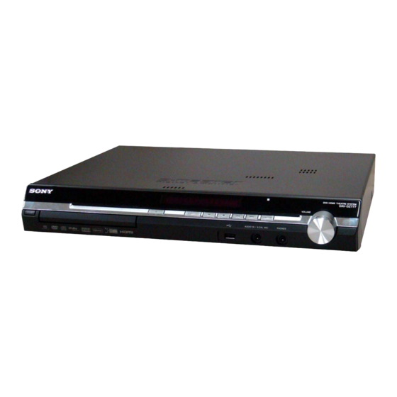
HCD-DZ370/DZ560/DZ570/
8
Photo : HCD-DZ777
Model Name Using Similar Mechanism
Mechanism Type
Optical Pick-up Name
Q Q
3
6 7
1 3
SPECIFICATIONS
108 W + 108 W (at 3 ohms,
1 kHz, 1% THD)
FL/FR/C/SL/SR*: 143
watts (per channel at 3
ohms, 1 kHz, 10% THD)
Subwoofer*: 285 watts (at
1.5 ohms, 80 Hz, 10%
THD)
Sensitivity: 250/125 mV
Sensitivity: 450/250 mV
Sensitivity: 250/125 mV
Sensitivity: 450/250 mV
Sensitivity: 450/250 mV
Sensitivity: 250/125 mV
Sensitivity: 450/250 mV
Sensitivity: 250/125 mV
u163
.
DZ660/DZ777
2 9
9 4
2 8
AEP Model
HCD-DZ560/DZ660
HCD-DZ370/DZ570/DZ777
Australian Model
HCD-DZ570/DZ777
HCD-DZ260/DZ270/HDZ278
CDM85-DVBU102
KHM-313CAA
1 5
0 5
8
2 9
9 4
Inputs (Digital) (DZ370/DZ570)
TV/VIDEO (COAXIAL IN/OPTICAL IN)
Impedance: 75 ohms/-
Inputs (Digital) (DZ560/DZ660/DZ777)
TV (COAXIAL IN/OPTICAL IN)
Impedance: 75 ohms/-
Outputs (Analog)
Phones
Accepts low- and high-
impedance headphones.
Super Audio CD/DVD System
Laser
Semiconductor laser
(Super Audio CD/DVD: λ
= 650 nm)
(CD: λ = 790 nm)
Emission duration:
continuous
Signal format system
Mexican and Latin American models:
NTSC
Other models:
NTSC/PAL
USB Section
Supported bit rate
MP3 (MPEG 1 Audio Layer-3):
32 kbps - 320 kbps
WMA:
48 kbps - 192 kbps
AAC:
48 kbps - 320 kbps
– Continued on next page –
m
DVD RECEIVER
co
9 9
UK Model
E Model
PX Model
HCD-DZ570
2 8
9 9
Advertisement
Table of Contents


Need help?
Do you have a question about the HCD-DZ370 and is the answer not in the manual?
Questions and answers