Advertisement
Quick Links
OPERATION MANUAL
Downey, CA
9459 Washburn Rd.
Downey, CA 90242
Phone- 800.252.1919
Fax- 562.862.3022
Toll free customer support: 1.800.252.1919
MODELS
MODELS
StudPro 2500
TWE-250
StudPro 3125
TWE-321
StudPro 3750
TWE-375
Hayward, CA
TRU‐WELD EQUIPMENT COMPANY
2391 American Ave.
Hayward, CA 94545
6400 N. HONEYTOWN ROAD
Phone- 510.782.7883
SMITHVILLE, OHIO 44677
Fax- 510.782.7918
(330) 669‐2773
Phoenix, AZ
3535 East Wier Ave., Ste. #4
Phoenix, AZ 85040
Phone- 602.305.9350
Fax- 602.305.4890
Renton, WA
927 Thomas Ave. SW
Renton, WA 98057
Phone- 425.656.9787
Fax- 425.656.9786
Advertisement

Related Manuals for stud welding products StudPro 2500


Summary of Contents for stud welding products StudPro 2500
- Page 1 OPERATION MANUAL MODELS MODELS StudPro 2500 TWE-250 StudPro 3125 TWE-321 StudPro 3750 TWE-375 Downey, CA Hayward, CA Phoenix, AZ Renton, WA TRU‐WELD EQUIPMENT COMPANY 9459 Washburn Rd. 2391 American Ave. 3535 East Wier Ave., Ste. #4 927 Thomas Ave. SW Downey, CA 90242...
- Page 2 CONTENTS Section Description Pages 1 Introduction Introduction 3 External Features 2 External Features 4‐5 Safety 3 Safety 6‐8 Setup and Welding 9-15 4 Setup and Welding 9‐15 Testing Weld Settings 16-19 5 Testing Weld Settings 16 Types of Fractures 6 Inspecting The Weld 17 Arc Blow Effect 7 CD Stud Gun Views 18 8 CD Stud Gun Exploded View 19 CD Stud Gun Exploded View 9 CD Stud Gun Parts List ...
- Page 3 INTRODUCTION The complete range of the capacitor discharge equipment is compact, portable stud welding equipment. The units are specifically designed to enable a small diameter range of ferrous and nonferrous weld studs to be welded to light gauge metal materi‐ als with little or no reverse‐side marking. The equipment consists of a control unit, a welding hand gun, and all necessary inter‐ connecting cables. THE PROCESS Capacitor Discharge (CD) stud welding is a form of welding in which the energy re‐ quired for the welding process is derived from a bank of charged capacitors. This stored energy is discharged at the base of the specially designed CD stud and it fuses the stud to the base material. The time of the weld is determined in such a short du‐ ration that no burn through marking is made on the finish side of the material. CONTACT In contact CD welding, the stud is placed under spring pressure on the material to be welded. When the capacitors are discharged, the special tip of the CD stud melts and the spring pressure forces the stud to fuse with the base material. GAP In gap CD welding, the stud is placed onto the material to be welded. As the stud gun is engaged, the stud lifts from the base material and then returns to the point of con‐ tact at the time of the discharge of the capacitors. As the capacitors discharge, melt‐ ing the tip of the weld stud, the pressure created by the movement of the stud to the base material by the stud gun fuses the stud to the base material. ...
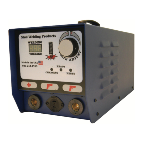
- Page 4 EXTERNAL FEATURES FRONT PANEL 1 2 3 4 5 6 1. Weld Voltage Selector ‐ rotate to change to required voltage. 2. Welding Voltage Digital Display ‐ displays selected voltage. 3. LED Lights ‐ Charging (capacitors are being charging to desired voltage), Ready (unit is ready to weld), Reset (indicates an error and unit should be turned off). 4. Welding Ground Cable Connector (+) 5. Stud Gun Control Connector 6. Welding Stud Gun Cable Connector (‐) ...
- Page 5 EXTERNAL FEATURES REAR PANEL 1.On/Off Switch 2.Fuse Holder (10 amp) 3.AC Power Cord 4.Manufacturer Model Number and Serial Number Plate WARNING! This unit operates from a 110 VAC 60 Hertz @10 amp circuit. Do not obstruct the ventilation fan, as this may cause unit to over heat. Do not remove any portion of the unit housing without first disconnecting the unit from the power supply. ON/OFF Switch ON/OFF Switch 15Amp Fuse 15Amp Fuse Power Supply Fan Power Supply Fan AC Cord AC Cord...
- Page 6 SAFETY PROTECT YOURSELF AND OTHERS! Read the safety notices before using welder. ELECTRICAL No portion of the outer cover of the welding controller should be removed by any‐ one other than qualified personnel. Always disconnect the unit from the main power prior to removing cover. This equipment contains a transformer power supply system, which is energized • by AC current and transforms the AC to DC current. Due to potential dangerous electrical input and output the equipment must be disconnected from all incom‐ ing power when servicing. Capacitors store electrical energy. Check for residual charge before performing • any maintenance. Do not use fluids to clean electrical components as these may penetrate the elec‐ • trical system and cause shorts. Connection of the unit into service must be in accordance with the setup procedures as detailed in this manual. Operation of this equipment must be in accordance with all local, regional, and national safety codes. ...
- Page 7 SAFETY FIRE During welding, small particles of hot metal can be expelled. Ensure that no combus‐ tible materials are near the welding area. FIRE HAZARD FROM SPARKS PERSONAL SAFETY Arc rays can burn your eyes and skin. Wear protective clothing and eye protection when welding. Loud noises from welding can damage hearing. Wear earplugs or other protective gear, if applicable. Fumes and gases expelled during welding can be hazardous to your health. Make sure welding is done in a well‐ventilated area. Hot metal splatter can cause fires and burns. Wear protective clothing, free of com‐ bustible materials. Have a fire extinguisher nearby and know how to use it. MAINTENANCE All cables must be inspected regularly to ensure that no danger exists from worn or damaged insulation or unsafe electrical connections. Take special note to the cables near the stud gun ‐ this is where maximum wear occurs. Worn cables not only produce inconsistent welds, but can overheat or spark. ...
- Page 8 SAFETY TRAINING Use of this equipment must be limited to authorized personnel only. They must be adequately trained, and have read and understood everything in this manual. The manual must be available to operators at all times. AUTHORIZED PERSONNEL ONLY INSTALLATION Select a site for the equipment which is capable of supporting the weight of the equipment, which is clear from traffic routes where people may trip over cables, or they may be damaged by other equipment or vehicles. Do not hang connecting cables over sharp edges or have near heat sources. DISPOSAL The equipment, in its entirety or as components/parts may be disposed of as general industrial waste or scrap. None of the components used in the manufacturing of the CD Welders are toxic, carcinogenic, or otherwise harmful to your health. ...
- Page 9 SET-UP AND WELDING POWERING UP THE EQUIPMENT Setup the equipment power supply (Control Unit) and connect to the main power, making certain of the proper voltage requirement of the particular unit. Capacitor Discharge (CD) units generally require 110 VAC @ 60Hz incoming power. Refer to the safety recommendations before plugging this unit in. ON/OFF Switch ON/OFF Switch Fuse Fuse Power Cord (110 VAC) Power Cord (110 VAC) CONNECTING THE WELDING LEADS Connect the welding ground cable into the (+) terminal mount socket on the front of the welding unit. ***NOTE ‐ the cable end plug has a flat which aligns with a dot on the panel mount socket. Secure the connector into the panel mount socket, and then turn it clockwise until it locks into proper position. Failure to do so could result in damage to the con‐ nector. Ground Cable Socket Ground Cable Socket...
- Page 10 SET-UP AND WELDING CONNECTING THE WELDING LEADS Connect the welding stud gun power cable into the (‐) terminal panel mount socket (designated by the gun symbol) on the front of the welding unit. ***NOTE ‐ the cable end plug has a flat which aligns with a dot on the panel mount socket. Secure the connector into the panel mount socket, and then turn it clockwise until it locks into proper position. Failure to do so could result in damage to the con‐ nector. Welding Gun Power Connector Welding Gun Power Connector Welding Gun Control Cable Connector Welding Gun Control Cable Connector Connect the weld gun control cable into the center panel 2‐pin socket. **NOTE ‐ the plug has a large pin and a small pin that match the socket on the unit. This is to prevent incorrect connections. Push the plug firmly into the socket and twist clockwise to secure the plug into the correct position. ...
- Page 11 SET-UP AND WELDING SET-UP AND WELDING CONNECTING THE GROUND CLAMP CONNECTING THE GROUND CLAMP Attach the clamp of the welding ground lead to the work piece. Prior to securing the Attach the clamp of the welding ground lead to the work piece. Prior to securing the clamp, make certain that the contact area is free of rust, paint, grease, or any other clamp, make certain that the contact area is free of rust, paint, grease, or any other impurities to ensure a good ground connection. impurities to ensure a good ground connection. NOTE***Most applications will require only one ground clamp, but certain applica‐ tions will require an additional dual clamp. NOTE***Most applications will require only one ground clamp, but certain applica‐ tions will require an additional dual clamp. ...
- Page 12 SET-UP AND WELDING SET-UP AND WELDING SELECTING THE PROPER STUD COLLET (STUD HOLDER) SELECTING THE PROPER STUD COLLET (STUD HOLDER) The collet is selected to the proper diameter that you are welding. The collet is selected to the proper diameter that you are welding. There are three styles of collets; There are three styles of collets; The “B” collet which is a two‐piece assembly (collet and insert). The insert deter‐ • The “B” collet which is a two‐piece assembly (collet and insert). The insert deter‐ • mines how much of the stud is engaged in the collet. mines how much of the stud is engaged in the collet. The CI (Collet Insert) which is a single part and the amount of the stud that is en‐ • The CI (Collet Insert) which is a single part and the amount of the stud that is en‐ • gaged is predetermined. gaged is predetermined. Standard Adjustable Chucks have an adjustable internal screw to manually adjust • Standard Adjustable Chucks have an adjustable internal screw to manually adjust • for the engagement of the stud. for the engagement of the stud. The choice between these systems is usually a matter of personal preference. The choice between these systems is usually a matter of personal preference. ...
- Page 13 SET-UP AND WELDING SET-UP AND WELDING SELECTING THE SPRING LOAD SELECTING THE SPRING LOAD The proper spring pre‐load setting on the stud gun will vary depending on the se‐ The proper spring pre‐load setting on the stud gun will vary depending on the se‐ lected application. Generals rules of application would be; mild steel or stainless lected application. Generals rules of application would be; mild steel or stainless steel usually in the 1 to 2 range, depending on the stud diameter and the thickness of steel usually in the 1 to 2 range, depending on the stud diameter and the thickness of the base material. Aluminum and other nonferrous metals would require settings the base material. Aluminum and other nonferrous metals would require settings from 3 to 5 depending on the diameter of the stud and base material thickness. from 3 to 5 depending on the diameter of the stud and base material thickness. Adjustment Cap Adjustment Screw Tension Indicator Tension Indicator This spring pre‐load adjustment is made by turning the screw insert in the back of the stud gun with a screwdriver. On the bottom of the back cap of the stud gun is the This spring pre‐load adjustment is made by turning the back cap of the stud gun. On indicator numbered 1 thru 5, which will show you the tension setting during the ad‐...
- Page 14 SET-UP AND WELDING READY FOR WELDING When you have completed all of the previous steps to prepare for welding, including connecting the stud gun and ground cables to the unit, attaching the ground cable(s) to the work area, setting up and adjusting the stud gun for the selected stud diame‐ ter and material, you can now power on the welder. ON/OFF Switch ON/OFF SWITCH FUSE FUSE The controller ON/OFF switch is located on the rear of the unit in the upper right hand corner. Below this switch is the 15amp fuse holder for the system. ...
- Page 15 Voltage Adjustment Knob Voltage Adjustment Knob Voltage Ad Approximate voltage staring points are listed below. Fine tuning the voltage to meet Approximate voltage staring points are listed below. F your requirement for your specific application is recommended. your requirement for your specific application is recom MODEL TWE‐321 & 375 MODEL T MODEL STUDPRO 2500 MODEL 3125 & 3750 Diameter Voltage (DC) Diameter Voltage (DC) Diameter Voltage (DC) Diameter 14 ga. 50‐75 14 ga. 50‐75 ...
- Page 16 TESTING WELD SETTINGS TESTING YOUR SETTINGS When you have performed all of the presets as discussed in this manual, it is recom‐ mended that you perform several test welds with the same diameter stud and base material that you will be using. This will verify that all of the settings are correct to the results you desire. Welding is done by placing the stud into the collet, and press‐ ing the stud gun to the work piece, compressing the spring. This is why the stud must protrude beyond the foot piece at least 1/8”. Holding the gun perpendicular to the work piece, and aligning the stud to the desired position on the work piece, press down so that the foot piece is flush with the work piece (spring compressed), and depress the trigger. When removing the stud gun from the welded stud, always lift the stud gun vertically from the welded stud in order to maintain the proper tension of the collet. Spreading the collet when lifting the stud gun from the welded stud will shorten the life of the collet and will eventually create an undesirable weld. ...
- Page 17 SET-UP AND WELDING TESTING WELD SETTINGS INSPECTING THE WELD TESTING YOUR SETTINGS Visually inspect the weld. A good weld will result in an all‐around weld, with a small When you have performed all of the presets as discussed in this manual, it is recom‐ visible amount of weld surrounding the flange of the stud. Too much splatter and the mended that you perform several test welds with the same diameter stud and base weld is too hot, lower the voltage. No splatter and the weld is too cold, increase the material that you will be using. This will verify that all of the settings are correct to voltage. the results you desire. Welding is done by placing the stud into the collet, and press‐ ing the stud gun to the work piece, compressing the spring. This is why the stud must If you get weld flash to one side of the stud as opposed to an even amount around protrude beyond the foot piece at least 1/8”. the base of the flange, this is called “arc blow”, and can be solved by repositioning the ground clamp or using a dual ground clamp. Holding the gun perpendicular to the work piece, and aligning the stud to the desired position on the work piece, press down so that the foot piece is flush with the work piece (spring compressed), and depress the trigger. Proper welded studs can be tested by either torquing or bending the stud. The welded flange of the stud should stay in place using either method, even though the threaded portion of the stud breaks. If the base material is very thin, then a full slug, the diameter of the flange will pull from the base metal for a properly welded stud. CD Stud Welding Steps ...
-
Page 18: Stud Welding Procedure
5 Stud Welding Procedure 5.8 Checking the Quality of the Weld TESTING WELD SETTINGS 5.8.1 Visual Inspection A visual inspection must be carried out with each welding element. TESTING YOUR SETTINGS Visual Inspection Condition Possible cause Corrective actions Good welded joint - Correct parameters - None Low spatters around the weld When you have performed all of the presets as discussed in this manual, it is recom‐... -
Page 19: Bending Test
5 Stud Welding Procedure 5.8 Checking the Quality of the Weld TESTING WELD SETTINGS 5.8.2 Bending Test You can purchase from SWP a bending device with inserts for various diameters of the welding elements. TESTING YOUR SETTINGS When you have performed all of the presets as discussed in this manual, it is recom‐ mended that you perform several test welds with the same diameter stud and base material that you will be using. This will verify that all of the settings are correct to the results you desire. Welding is done by placing the stud into the collet, and press‐ ing the stud gun to the work piece, compressing the spring. This is why the stud must protrude beyond the foot piece at least 1/8”. ... - Page 20 5 Stud Welding Procedure TYPES OF FRACTURES 5.8 Checking the Quality of the Weld SET-UP AND WELDING Bending Test Type of fracture Possible cause Corrective actions Base material buckling - Correct parameters - none INSPECTING THE WELD Visually inspect the weld. A good weld will result in an all‐around weld, with a small visible amount of weld surrounding the flange of the stud. Too much splatter and the Fracture in the welding element - Correct parameters - none weld is too hot, lower the voltage. No splatter and the weld is too cold, increase the ...
-
Page 21: Arc Blow Effect
5 Stud Welding Procedure ARC BLOW EFFECT 5.8 Checking the Quality of the Weld SET-UP AND WELDING 5.8.3 Arc Blow Effect A so called arc blow effect can occur with unproportionally distributed ground connec- tions in relation to the base material mass, varying material distribution, or welding at INSPECTING THE WELD ... - Page 22 CD Gun Exploded View 23 ...
- Page 23 Internal Components 1. 2. 3. 4. 5. 6. 1. TWE01013 ‐‐‐ CD Rocker switch 2. TWE01012 ‐‐‐ CD 15 Amp Breaker 3. TWE0851CD ‐‐‐ AC Inline Filter 4. TWE01004 ‐‐‐ Capacitor (2) 5. TWE103621‐005 ‐‐‐ CD Capacitor Bracket 6. TWE103621‐006 ‐‐‐ CD Capacitor Bridge Link ...
- Page 24 Internal Components 1. 2. 3. 4. 5. 6. 7. 8. 10. 11. 1. TWE01001 ‐‐‐ PC Board 2. TWE01002/TWE01003 ‐‐‐ CD Thyristor /Clamp 3. TWE01011‐‐‐ CD Flyback Diode 4. TWE01010 ‐‐‐ CD TRIAC 5. TWE01009 ‐‐‐ CD Bridge Rectifier 6. TWE01015 ‐‐‐ CD Fan 7. TWE01019 ‐‐‐ CD Terminal Block 8. TWE01006 ‐‐‐ Main Wire Harness 9. TWE01014 ‐‐‐ Power Relay 10. TWE01005 ‐‐‐ CD Main Transformer 10. TWE01008 ‐‐‐ CD Power Resistor 21 ...
- Page 25 Internal Components 1. 2. 3. 1. 107‐0031 ‐‐‐ Control Panel Mount 2. 107‐0002 ‐‐‐ Camlock Panel Mount 3. TWE01017 ‐‐‐ Voltage Adjustment Knob 22 ...
- Page 26 CAPACITOR DISCHARGE ACCESSORIES ONE PIECE CONTACT/MAGNETIC CHUCK PART NO. PRICE 039 613 36.00 MAGNETIC CHUCK PART NO. DESCRIPTION PRICE 035 301 COMPLETE ASSY 49.00 017 633 MAGNET ONLY 40.00 029 615 CONDUCTOR PLATE 20.00 039 609 INSUL. TUBE 9.00 039 610 INSUL.
- Page 27 CAPACITOR DISCHARGE ACCESSORIES COLLETS INSERTS FOR WELD STUDS COLLETS INSERTS FOR WELD PINS 1/4 DIA 1-3/4” STUD DIA. X DEPTH PART NO. PRICE STUD DIA. 12GA X 1/2 CIP 010 050 18.00 X DEPTH PART NO. PRICE 12GA X 3/4 CIP 010 075 18.00 #4 X 1/4...
- Page 28 2-3/8 LONG & KSM LONG STYLE COLLETS 3/8”DIA. 2-3/8” STUD SIZE PART NO. OTHER PART # PRICE CDBN 013 500 001 356 17.00 CDBN 015 500 001 357 17.00 CDBN 018 500 001 366 17.00 CDBN 025 500 001 359 17.00 5/16 CDBN 031...
- Page 29 ADAPTORS B CI ADAPTOR K B ADAPTORS 1/4-20 3/8 DIA 1/4 DIA 3/8 DIA 1-3/4 PARTNO. PRICE PART NO. PRICE 044 082 7/8 LONG 17.00 039 464 45.00 033 746 1 9/16 LONG 13.00 B N ADAPTOR K N ADAPTORS 1/4-20 TAPER TAPER...
- Page 30 STUD WELDING PRODUCTS, INC. STUD WELDING PRODUCTS, INC. Torque Bending Test Torque Bending Test Application Application Non-destructive test method for studs welded with tip ignition (CD) and short cycle (SC) process. Torque check of the welded studs for quality assurance.
- Page 31 STUD WELDING PRODUCTS, INC. Torque Bending Test Instructions Depending on the test job, adjust the test torque of the Select the test insert depending on stud diameter, torque wrench. Adjust the test torque in such a way that push it on a torque wrench and fix it.
- Page 32 STUD WELDING PRODUCTS, INC. GUN SET UP CD Models 30mm Template Tube CD Foot Collet Extender Tri Pod Made in the Shaft Extender with “B” Collet Check us out on the internet www.studweldprod.com or email info@studweldprod.com Downey, CA Hayward, CA...
- Page 33 STUD WELDING PRODUCTS, INC. GUN SET UP Insulation Models “B” Collet with CD Foot Piece and Spark Shield Magnetic Chuck with HBS Insulation Push Down “B” Collet with CD Foot Piece Magnetic Chuck Made in the “B” Collet with Collet Protector Check us out on the internet www.studweldprod.com or email info@studweldprod.com...
Need help?
Do you have a question about the StudPro 2500 and is the answer not in the manual?
Questions and answers