Table of Contents
Advertisement
Installation
&
Maintenance
Manual
INVERTER-DRIVEN
SPLIT SYSTEM
HEAT PUMP
AIR CONDITIONERS
- DC INVERTER UTOPIA -
Models:
Outdoor Units;
RAS-3HVRNM2
RAS-4HVRNM2
RAS-5HVRNM2
RAS-6HVRNM2
RAS-7HVRNM2
IMPORTANT:
READ AND UNDERSTAND
THIS MANUAL BEFORE
USING THIS HEAT-PUMP
AIR CONDITIONERS.
KEEP THIS MANUAL FOR
FUTURE REFERENCE.
TC-12001
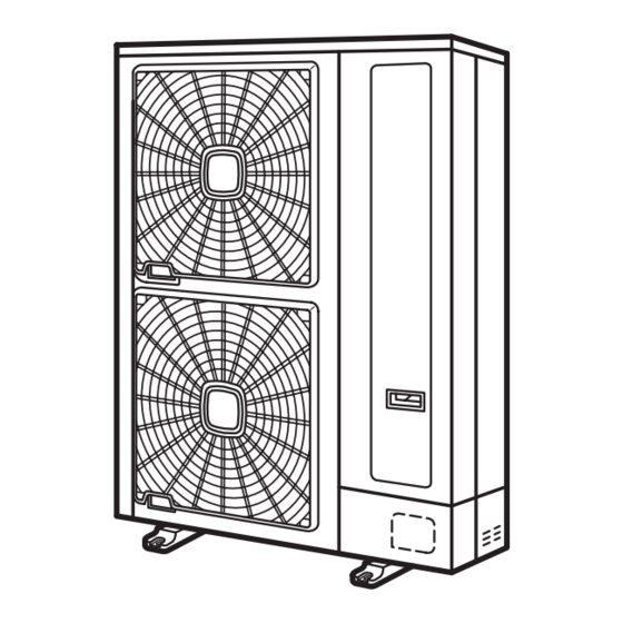
OUTDOOR UNIT
P5414950
2-73
Advertisement
Table of Contents


Need help?
Do you have a question about the RAS-3HVRNM2 and is the answer not in the manual?
Questions and answers