
Related Manuals for Sony XM-7547


Summary of Contents for Sony XM-7547
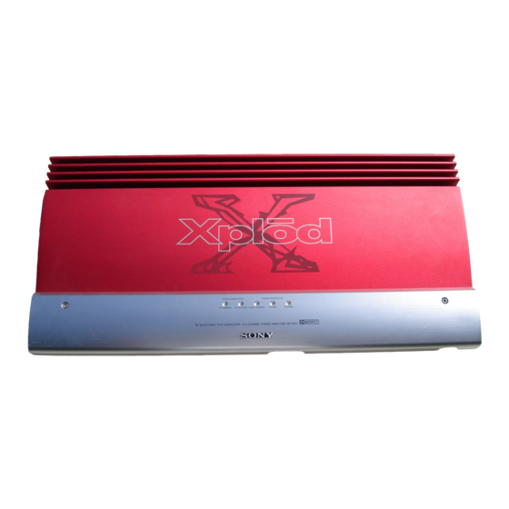
- Page 1 XM-7547 SERVICE MANUAL US Model Canadian Model AEP Model UK Model E Model SPECIFICATIONS STEREO POWER AMPLIFER MICROFILM...
-
Page 2: Table Of Contents
Notes on chip component replacement TABLE OF CONTENTS • Never reuse a disconnected chip component. • Notice that the minus side of a tantalum capacitor may be 1. SERVICE MODE ............. 3 damaged by heat. 2. GENERAL ................4 3. DISASSEMBLY 3-1. -
Page 3: Service Mode
SECTION 1 SERVICE NOTE Clearing the Protector During Repairs • OVER CURRENT : Detects overcurrent during output. • OFF SET : Detects DC offset at the speaker terminal. 1. Clearing the OVER CURRENT protector 1 When the position of the MODE switch (S801/power board) is set to HI-VOLTAGE : Cut the jumper wire JW535 of the amplifier board. -
Page 4: General
SECTION 2 This section is extracted from instruction manual. GENERAL... -
Page 7: Disassembly
SECTION 3 SECTION 4 DISASSEMBLY ELECTRICAL ADJUSTMENT Note: Follow the disassembly procedure in the numerical order given. Adjustment Location IDLING CURRENT ADJUSTMENT 3-1. SIDE PLATE AND FILTER BOARD - AMPLIFIER BOARD - (Component side) 2 Four screws • Perform adjustments in the HI-VOLTAGE mode. 1 Three screws (BTP3x8) (BTP3x8) -
Page 8: Diagrams
XM-7547 SECTION 5 DIAGRAMS 5-1. BLOCK DIAGRAM – AMPLIFIER SECTION – DIRECT LINE SWITCH Q102 S805-1 SPEAKER OUT OVERLOAD DIFFERENTIAL POWER AMP Q114,116 (VOLTAGE STAGE) CN810 LOWBOOST LINE SWITCH PRE AMP H.P.F H.P.F L.P.F L.P.F CNJ808 Q104,106 Q108 IC806-1 Q103... -
Page 9: Block Diagram - Power Section
XM-7547 5-2. BLOCK DIAGRAM – POWER SECTION – POWER BOARD LED BOARD D803 D804 D805 OVER CURRENT OFFSET THERMAL CNB805 CNP804 OFFSET LED MODE OFFSET CONTROL Q809-810 S801-1 Q804 D801 D802 AMPLIFIER D806 HI-VOLTAGE HI-CURRENT BOARD CNP805 HI-C HI-V MUTE ENABLER... -
Page 10: Ic Block Diagram
XM-7547 5-4. PRINTED WIRING BOARD – LED/FILTER SECTION – THIS NOTE IS COMMON FOR PRINTED WIRING BOARDS AND SCHEMATIC DIAGRAMS. (In addition to this, the necessary note is printed in each block.) FILTER BOARD For schematic diagrams. Note: JW125 JW108 •... -
Page 11: Schematic Diagram - Filter/Amplifier (1/3) Section
XM-7547 5-5. SCHEMATIC DIAGRAM – FILTER/AMPLIFIER (1/3) SECTION – • See page 10 for IC Block Diagram. AMPLIFIER BOARD C889 C886 Q102 2SC3327-A S805-1 LINE SW CNP808 9P CNJ808 9P R108 R114 IC806-1 3.3k S801-3 NJM4580E(T1) S801-1 C154 VR805 0.15... -
Page 12: Printed Wiring Board - Amplifier Section
XM-7547 5-6. PRINTED WIRING BOARD – AMPLIFIER SECTION – CN811 CN810 FILTER BOARD FILTER BOARD SPEAKER OUT CNJ807 SPEAKER OUT • Semiconductor Location CNJ809 CNJ808 MONO INPUT MONO (Page 10) (Page 10) AMPLIFIER BOARD MONO-R MONO-L Ref. No. Location Ref. No. -
Page 13: Schematic Diagram - Amplifier (2/3) Section
XM-7547 5-7. SCHEMATIC DIAGRAM – AMPLIFIER (2/3) SECTION – • See page 10 for IC Block Diagram. Q113 R134 42.9 R146 10K 2SA1162-Y AMPLIFIER BOARD R147 10K Q104-107 R124 R118 C110 Q108 R138 R150 D103 42.3 DIFFERENTIAL 4.7K 2SA1360-Y 26.8 0.06X2 5W... -
Page 14: Schematic Diagram - Power/Amplifier (3/3)/Led Section
XM-7547 5-8. SCHEMATIC DIAGRAM – POWER/AMPLIFIER (3/3)/LED SECTION – • See page 10 for IC Block Diagram. AMPLIFIER BOARD TO AMPLIFIER BOARD (1/3) TO AMPLIFIER BOARD (2/3) (Page 13) TO AMPLIFIER BOARD (Page 13) (Page 11) (2/3) D854 +45V C861... -
Page 15: Printed Wiring Board - Power Section
XM-7547 5-9. PRINTED WIRING BOARD – POWER SECTION – POWER BOARD (SIDE A) • Semiconductor Location Ref. No. Location D806 D807 R820 R835 D808 C921 C902 D901 D902 D807 D902 D901 R837 R903 R904 D904 D808 D907 Q902 D908 D909... - Page 16 XM-7547 CN802 CNJ801 REMOTE +12V +12V POWER BOARD (SIDE B) • Semiconductor MODE Location HI-C HI-V F901 F902 F903 F904 S802 S801 Ref. No. Location CNJ801 C806 R838 D809 D903 D809 D905 D906 IC813 LED BOARD AMPLIFIER D910 CNB804 BOARD...
-
Page 17: Exploded Views
Description Remark Ref. No. Part No. Description Remark 3-039-168-01 PANEL (R), SIDE 3-704-177-11 EMBLEM (No. 7), SONY 3-039-205-01 HEAT SINK (COVER) 3-039-173-01 PLATE (BKT), BOTTOM 3-040-933-01 BOLT, M4 HEXAGON HOLE 3-039-170-01 LENS(COVER) F901 1-576-256-11 FUSE (BLADE TYPE) (AUTO FUSE) (25A) -
Page 18: Board And Heat Sink
6-2. BOARD AND HEAT SINK SECTION (Including Ref No.62) (Including Ref No.55) (Including Ref No.55) (Including Ref No.55) (Including Ref No.55) Ref. No. Part No. Description Remark Ref. No. Part No. Description Remark * 51 3-039-210-01 HEAT SINK (US,CND) * 59 3-039-200-01 BRACKET (PWB) * 51 3-039-210-11 HEAT SINK (AEP,UK,E) -
Page 19: Electrical Parts List
SECTION 7 AMPLIFIER ELECTRICAL PARTS LIST Note: • Due to standardization, replacements in the parts list • SEMICONDUCTORS When indicating parts by reference In each case, u: µ , for example: may be different from the parts specified in the number, please include the board uA...: µ... - Page 20 AMPLIFIER Ref. No. Part No. Description Remark Ref. No. Part No. Description Remark C865 1-126-009-81 ELECT 100uF D106 8-719-100-65 DIODE RD12EB2 C866 1-126-009-81 ELECT 100uF D201 8-719-025-50 DIODE 02CZ16-TE85L D202 8-719-025-50 DIODE 02CZ16-TE85L C867 1-164-004-11 CERAMIC CHIP 0.1uF D203 8-719-820-05 DIODE 1SS181-TE85R C868 1-164-004-11 CERAMIC CHIP 0.1uF...
- Page 21 AMPLIFIER Ref. No. Part No. Description Remark Ref. No. Part No. Description Remark Q110 8-729-207-82 TRANSISTOR 2SC3421-Y Q852 8-729-230-49 TRANSISTOR 2SC2712-Y Q853 8-729-141-83 TRANSISTOR 2SB1375 Q111 8-729-049-52 TRANSISTOR FS70SMJ-2 Q854 8-729-230-49 TRANSISTOR 2SC2712-Y Q112 8-729-049-53 TRANSISTOR FX50SMJ-2 Q855 8-729-205-88 TRANSISTOR 2SC3074-Y(TE16L) Q113 8-729-216-21 TRANSISTOR...
- Page 22 AMPLIFIER Ref. No. Part No. Description Remark Ref. No. Part No. Description Remark R150 1-208-462-61 RES,CHIP 1/10W R254 1-249-568-11 CARBON 4.7K 1/4W R151 1-208-462-61 RES,CHIP 1/10W R255 1-249-943-11 CARBON 6.8K 1/4W R152 1-208-550-61 RES,CHIP 470K 1/10W R256 1-249-576-11 CARBON 1/4W R153 1-217-784-11 FUSIBLE R154...
- Page 23 AMPLIFIER Ref. No. Part No. Description Remark Ref. No. Part No. Description Remark R401 1-208-518-61 RES,CHIP 1/10W R858 1-208-453-61 RES,CHIP 4.7K 1/10W R859 1-208-462-61 RES,CHIP 1/10W R402 1-208-518-61 RES,CHIP 1/10W R860 1-208-539-11 RES,CHIP 160K 1/10W R403 1-208-291-11 RES,CHIP 4.7M 1/10W R861 1-208-539-11 RES,CHIP 160K...
- Page 24 FILTER Ref. No. Part No. Description Remark Ref. No. Part No. Description Remark 1-675-246-11 FILTER (4CH) BOARD R187 1-216-057-61 RES,CHIP 2.2K 1/10W R189 1-208-462-61 RES,CHIP 1/10W ***************** R190 1-208-462-61 RES,CHIP 1/10W < CAPACITOR > R281 1-208-462-61 RES,CHIP 1/10W C151 1-163-251-11 CERAMIC CHIP 100PF R282 1-208-518-61 RES,CHIP...
- Page 25 POWER Ref. No. Part No. Description Remark Ref. No. Part No. Description Remark Q803 8-729-230-49 TRANSISTOR 2SC2712-Y C935 1-104-829-11 ELECT 220uF < RESISTOR > C936 1-104-829-11 ELECT 220uF C937 1-163-021-11 CERAMIC CHIP 0.01uF R801 1-216-194-00 METAL CHIP 1/8W C944 1-163-021-11 CERAMIC CHIP 0.01uF R802 1-216-194-00 METAL CHIP...
- Page 26 POWER Ref. No. Part No. Description Remark Ref. No. Part No. Description Remark Q805 8-729-230-49 TRANSISTOR 2SC2712-Y R835 1-216-698-11 METAL CHIP 0.5% 1/10W Q806 8-729-230-49 TRANSISTOR 2SC2712-Y Q807 8-729-230-49 TRANSISTOR 2SC2712-Y R836 1-208-437-61 RES,CHIP 1/10W Q808 8-729-216-21 TRANSISTOR 2SA1162-Y R837 1-208-510-61 RES,CHIP 1/8W R838...
- Page 27 POWER Ref. No. Part No. Description Remark Ref. No. Part No. Description Remark R955 1-216-631-11 METAL CHIP 0.5% 1/10W ACCESSORIES R956 1-216-631-11 METAL CHIP 0.5% 1/10W ************ R957 1-215-886-11 METAL OXIDE R958 1-215-886-11 METAL OXIDE 3-867-641-11 MANUAL, INSTRUCTION (ENGLISH,FRENCH) 3-867-641-21 MANUAL, INSTRUCTION R959 1-208-437-61 RES,CHIP 1/10W...
- Page 28 XM-7547 Sony Corporation 9-926-591-11 99F09278-1 Mobile Electronics Company Printed in Japan © 1999. 6 Published by Quality Assurance Dept.
Need help?
Do you have a question about the XM-7547 and is the answer not in the manual?
Questions and answers