Table of Contents
Advertisement
Quick Links
QQ
3 7 63 1515 0
TE
L 13942296513
CONTENTS
TO SERVICE PERSONNEL ........................................... 1
REMOTE CONTROL PANEL ......................................... 1
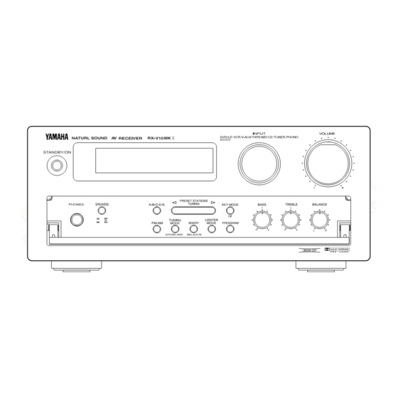
FRONT PANELS ............................................................. 2
REAR PANELS ............................................................... 3
SPECIFICATIONS ....................................................... 4~5
INTERNAL VIEW ............................................................ 6
DISASSEMBLY PROCEDURES .................................... 6
SELF CHECK MODE .................................................. 7~9
AMP ADJUSTMENT ..................................................... 10
www
.
1 0 0 6 5 6
http://www.xiaoyu163.com
RX-V10MK 2 2 2 2 2
This manual has been provided for the use of authorized YAMAHA Retailers and their service personnel.
It has been assumed that basic service procedures inherent to the industry, and more specifically YAMAHA
Products, are already known and understood by the users, and have therefore not been restated.
WARNING:
IMPORTANT:
The data provided is believed to be accurate and applicable to the unit(s) indicated on the cover. The research,
engineering, and service departments of YAMAHA are continually striving to improve YAMAHA products.
Modifications are, therefore, inevitable and specifications are subject to change without notice or obligation
to retrofit. Should any discrepancy appear to exist, please contact the distributor's Service Division.
WARNING:
IMPORTANT:
x
ao
u163
y
i
http://www.xiaoyu163.com
2 9
8
AV RECEIVER
SERVICE MANUAL
IMPORTANT NOTICE
Failure to follow appropriate service and safety procedures when servicing this product
may result in personal injury, destruction of expensive components, and failure of the
product to perform as specified. For these reasons, we advise all YAMAHA product
owners that any service required should be performed by an authorized YAMAHA
Retailer or the appointed service representative.
Q Q
3
6 7
1 3
1 5
The presentation or sale of this manual to any individual of firm does not constitute
authorization, certification or recognition of any applicable technical capabilities,
or establish a principle-agent relationship of any form.
Static discharges can destroy expensive components. Discharge any static electricity
your body may have accumulated by grounding yourself to the ground buss in the unit
(heavy gauge black wires connect to this buss).
Turn the unit OFF during disassembly and part replacement. Recheck all work before
you apply power to the unit.
IC DATA .................................................................. 15~20
DISPLAY DATA ........................................................... 21
BLOCK DIAGRAM .................................................. 22~25
PRINTED CIRCUIT BOARD ................................... 26~39
SCHEMATIC DIAGRAM ......................................... 40~43
PARTS LIST ............................................................ 44~55
REMOTE CONTROL TRANSMITTER ......................... 56
co
.
9 4
2 8
0 5
8
2 9
9 4
2 8
m
9 9
9 9
Advertisement
Table of Contents

Related Manuals for Yamaha RX-V10MK II


Summary of Contents for Yamaha RX-V10MK II
-
Page 1: Table Of Contents
SERVICE MANUAL IMPORTANT NOTICE This manual has been provided for the use of authorized YAMAHA Retailers and their service personnel. It has been assumed that basic service procedures inherent to the industry, and more specifically YAMAHA Products, are already known and understood by the users, and have therefore not been restated. -
Page 2: To Service Personnel
http://www.xiaoyu163.com RX-V10MK 2 2 2 2 2 3 7 63 1515 0 TO SERVICE PERSONNEL 1. Critical Components information. Components having special characteristics are marked and AC LEAKAGE must be replaced with parts having specifications equal to WALL EQUIPMENT TESTER OR OUTLET UNDER TEST EQUIVALENT... -
Page 3: Front Panels
http://www.xiaoyu163.com RX-V10MK 2 2 2 2 2 3 7 63 1515 0 FRONT PANELS R model SPEAKERS B ,G models L 13942296513 SPEAKERS RDS MODE/FREQ PTY SEEK MODE START u163 http://www.xiaoyu163.com... -
Page 4: Rear Panels
MODE REAR CENTER REAR NTSC WOOFER AC OUTLETS 100W MAX. TOTAL WOOFER CENTER SWITCHED MODEL NO. RX-V10MK2 110/120/220/240VOLTS 160WATTS 50/60Hz YAMAHA CORPORATION MAIN MADE IN MALAYSIA 50kHz 9kHz 10kHz 100kHz FM AM MAIN SURROUND FREQUENCY 8ΩMIN./SPEAKER VIDEO AUDIO SIGNAL 6CH DISCRT INPUT... -
Page 5: Specifications
http://www.xiaoyu163.com RX-V10MK 2 2 2 2 2 3 7 63 1515 0 SPECIFICATIONS Tone Control Characteristics AUDIO SECTION ±10dB(50Hz) BASS : Boost/Cut Minimum RMS output Power per Channel : Turnover Frequency 350Hz (Power Amp. Section) ±10dB(20kHz) TREBLE : Boost/Cut MAIN : Turnover Frequency 3.5kHz 20Hz to 20kHz, 0.04% THD, 8Ω... - Page 6 http://www.xiaoyu163.com RX-V10MK 2 2 2 2 2 3 7 63 1515 0 DIMENSIONS AM SECTION Tuning Range R model 531 to 1611/530 to 1710kHz B, G, models 531 to 1611kHz Usable Sensitivity 300µV/m Output Level(1kHz) 30% mod. 150mV Signal to Noise Ratio 50dB Antenna Loop antenna...
- Page 7 http://www.xiaoyu163.com RX-V10MK RX-V10MK 2 2 2 2 2 2 2 2 2 2 3 7 6 3 1 5 1 5 0 Parts List for Carbon Resistors REMOTE CONTROL TRANSMITTER Value 1/4W Type Part No. 1/6W Type Part No. Value 1/4W Type Part No.
- Page 8 http://www.xiaoyu163.com RX-V10MK 2 2 2 2 2 3 7 63 1515 0 SELF CHECK MODE This machine has the SELF CHECK MODE (SELF) for facilitating inspectional measurement. HOW TO EXIT HOW TO START (2 options) Turning the POWER switch OFF or pressing the KEY MODE SELF CHECK MODE with MAKER PRESET or Remote Control Transmitter ENHANCED key cancels the Turn the POWER switch ON while pressing the CENTER...
- Page 9 http://www.xiaoyu163.com RX-V10MK 2 2 2 2 2 3 7 63 1515 0 CONTENTS OF SELF CHECK MODE SELF Remote Control Select key Supplement Menu Transmitter FM/AM TEST • At first, SELF No. is 1, INPUT is CD, SWFR LEVEL is set RAM THROUGH A TUNING MODE EFFECT...
- Page 10 http://www.xiaoyu163.com RX-V10MK 2 2 2 2 2 3 7 63 1515 0 SELF 3 RAM THROUGH C SELF 5 DSP OFF L/R is output through the DSP. L/R output through the bypass. CENTER is output with the steering OFF and by (L+R)/2 The FL displays "C 5".
-
Page 11: Amp Adjustment
http://www.xiaoyu163.com RX-V10MK 2 2 2 2 2 3 7 63 1515 0 AMP ADJUSTMENT Confirmation and Adjustment of Iding Current of Main Amplifier Right after power is turned on, confirm that the voltage across the terminals of CB111,CB112 and CB113 is between 0.1mV~3.0mV. If it exceeds 3.0mV, open (cut off) R120 (on CB111), R127 (on CB112) or R134 (on CB113) and reconfirm the voltage again. -
Page 12: Tuner Adjustment
http://www.xiaoyu163.com RX-V10MK 2 2 2 2 2 3 7 63 1515 0 TUNER ADJUSTMENT 1. Measuring Instruments Dummy antenna FM signal generator (FM SG) FM dummy antenna Stereo signal generator (SSG) Ω Ω AM signal generator (AM SG) Distortion meter (DIS. M) RECEIVER FM SG AC Voltmeter (ACVM) - Page 13 http://www.xiaoyu163.com RX-V10MK 2 2 2 2 2 3 7 63 1515 0 FM Adjustment 1. Befor Adjustment Set each switch to the following position unless otherwise For dBµ, 1µV=0dBµ applies. specified. Example : 60dBµ=1mV INPUT SELECTOR ..TUNER 100% modulation means that the frequency deviation is TUNING MODE .....
- Page 14 http://www.xiaoyu163.com RX-V10MK 2 2 2 2 2 3 7 63 1515 0 Reception Adjustment Step Adjustment item Signal (ANT IN) Test point Rating frequency point Adjustment of FM ANT (75Ω) 98.1MHz Front end IFT Adjust so that the meter is front end IFT 98.1MHz (A-4)
- Page 15 http://www.xiaoyu163.com RX-V10MK 2 2 2 2 2 3 7 63 1515 0 AM Adjustment (This should be done after FM adjustment.) 1. Connection DIAGRAM (Measuring instruments) Adjustment of sensitivity. AM loop antenna ACVM TUNER dummy P. C. B. antenna DIST. M Oscilloscope See page 11 for TP locations &...
- Page 16 http://www.xiaoyu163.com RX-V10MK 2 2 2 2 2 3 7 6 3 1 5 1 5 0 BLOCK DIAGRAM (1/2) B, G models RF AMP B, G models LOCAL OSC LA2232 BUFFER BI-PHASE DEMOD FM DET COIL AM/FM IF DET. CLOCK DIFF DECODE SENSITIVITY LA1266...
- Page 17 http://www.xiaoyu163.com RX-V10MK 2 2 2 2 2 3 7 6 3 1 5 1 5 0 BLOCK DIAGRAM (2/2) INPUT EQ. AMP SELECTOR PHONO IC713 IC601 DOLBY PROLOGIC DECODER IC705 V-AUX IC652 IC712 TAPE/MD IC706 IC714 IC703 IC707 L.P.F. AUDIO INPUT IC651 SIGNAL...
- Page 18 http://www.xiaoyu163.com RX-V10MK 2 2 2 2 2 3 7 63 1515 0 INTERNAL VIEW 1 MAIN P.C.B. ASS'Y (10) 2 POWER TRANSFORMER 3 MAIN P.C.B. ASS'Y (3) CB191 4 MAIN P.C.B. ASS'Y (8) (R model only) 5 MAIN P.C.B. ASS'Y (6) 6 MAIN P.C.B.
-
Page 19: Ic Data
http://www.xiaoyu163.com RX-V10MK 2 2 2 2 2 3 7 63 1515 0 IC DATA IC401 : M38B59MFH-A100FP µ 8 bit -COM TOP VIEW L 13942296513 P00 – P08 P11 – P17 P20 – P27 P30 – P37 P40 – P47 56–49 48–44 64–57... - Page 20 http://www.xiaoyu163.com RX-V10MK 2 2 2 2 2 3 7 63 1515 0 No. Port Function Remarks Function Remarks No. Port Meter input Volume up Stereo input Volume down SIGIN (station detect) Self check ST0 (IF OK signal) DSP C DSP B STRQ (IF count request) L: MONO DSP A...
- Page 21 http://www.xiaoyu163.com RX-V10MK 2 2 2 2 2 3 7 63 1515 0 IC703 : YSS203B-F Digital Dolby Pro Logic Decoder Sync O Sync I TI/O /CSS TSBWD D GND D VDD A GND A VDD 40,41 26,58 14,15 4,25 2,3,57 59,61,62 TIMING GENERATOR...
- Page 22 http://www.xiaoyu163.com RX-V10MK 2 2 2 2 2 3 7 63 1515 0 IC703 : YSS203B-F Digital Dolby Pro Logic Decoder No. Name Function No. Name Function Word clock for parameter data input Serial data of parameter data input Bit clock for parameter data input TSBWD LSI test, Normally DVDD Nomally unconnected...
- Page 23 http://www.xiaoyu163.com RX-V10MK 2 2 2 2 2 3 7 63 1515 0 IC803 : LC74781-9626 Superimpose 24 VDD1 VSS1 23 RST XTAL IN XTAL OUT 22 CTRL3 CTRL1 21 CTRL2 BLANK 20 SEP IN OSC IN 19 SEP OUT 18 SEPC OSC OUT 17 SYN IN CHARA...
-
Page 24: Display Data
http://www.xiaoyu163.com RX-V10MK 2 2 2 2 2 3 7 6 3 1 5 1 5 0 DISPLAY DATA Terminal name Function Name V401 : 13-BT-143GK (VU105900) Connection to GND (Digital system ground terminal) VSS1 Ground terminal Crystal oscillation Terminal to connect the crystal of the crystal oscillator for internal synchronous signal generation XTAL IN and a capacitor or to input an external clock. -
Page 25: Printed Circuit Board
http://www.xiaoyu163.com RX-V10MK 2 2 2 2 2 3 7 6 3 1 5 1 5 0 PRINTED CIRCUIT BOARD (Foil side) FUNCTION P. C. B. ( 3 ) FUNCTION P. C. B. ( 4 ) BASS TREBLE BALANCE #323 W323 VOLUME(1) SPEAKERS W321... - Page 26 http://www.xiaoyu163.com RX-V10MK 2 2 2 2 2 3 7 6 3 1 5 1 5 0 PRINTED CIRCUIT BOARD (Foil side) 6 : TEST POINT WAVEFORMS(See page 40) Semiconductor Location Ref. No. Location FUNCTION P. C. B. ( 1 ) D701 D702 D703...
- Page 27 http://www.xiaoyu163.com RX-V10MK 2 2 2 2 2 3 7 6 3 1 5 1 5 0 PRINTED CIRCUIT BOARD (Foil side) 4,5 : TEST POINT WAVEFORMS(See page 40) FUNCTION P. C. B. ( 2 ) TUNING B, G only CENTER MODE MEMORY VOLUME(1)
- Page 28 http://www.xiaoyu163.com RX-V10MK 2 2 2 2 2 3 7 6 3 1 5 1 5 0 PRINTED CIRCUIT BOARD (Foil side) B, G models R model MAIN P. C. B. ( 3 ) MAIN P. C. B. ( 3 ) MAIN P.
- Page 29 http://www.xiaoyu163.com RX-V10MK 2 2 2 2 2 3 7 6 3 1 5 1 5 0 PRINTED CIRCUIT BOARD (Foil side) MAIN P. C. B. ( 1 ) MAIN P. C. B. ( 6 ) Semiconductor Location Ref. No. Location D101 D102 #104...
- Page 30 http://www.xiaoyu163.com RX-V10MK 2 2 2 2 2 3 7 6 3 1 5 1 5 0 PRINTED CIRCUIT BOARD (Foil side) 1 ~ 3 : TEST POINT WAVEFORMS(See page 43) R model TUNER P. C. B. Semiconductor Location R model TUNER P.C.B.
- Page 31 http://www.xiaoyu163.com RX-V10MK 2 2 2 2 2 3 7 6 3 1 5 1 5 0 PRINTED CIRCUIT BOARD (Foil side) VOLUME P. C. B. ( 2 ) VOLUME P. C. B. ( 3 ) VOLUME P. C. B. ( 1 ) W551 FUNCTION(2) VOLUME...
-
Page 32: Schematic Diagram
http://www.xiaoyu163.com RX-V10MK 2 2 2 2 2 SCHEMATIC DIAGRAM (FUNCTION) TO TUNER (B,G only) BUFFER IC BLOCK REAR SYSTEM 10.8 (Lch) CONTROL IC704-707, 710, 711 : uPC4570G2 C823 0.01 (J,B,G only) Dual OP-Amp -13.4 DOLBY PRO LOGIC -13.4 DECODER A OUT MULTIPLEXER/ 13.4 A –IN... - Page 33 http://www.xiaoyu163.com RX-V10MK 2 2 2 2 2 SCHEMATIC DIAGRAM (MAIN) MUTING MAIN REAR POWER AMP (Lch) SUB POWER SUPPLY WOOFER REAR(Lch) AUDIO 35.6 SIGNAL AC36.3 C924:1000P(R,B,G) 10.8 0.01(J) VOLTAGE SELECTOR REAR(Lch) VIDEO REAR L VIDEO1 AC OUTLETS REAR R VIDEO2 VIDEOR SPEAKER CENTER...
- Page 34 http://www.xiaoyu163.com RX-V10MK 2 2 2 2 2 • SCHEMATIC DIAGRAM (TUNER) The voltages are measured FM (98.1 MHz, STEREO) reception mode. Only the voltages in ( ) are in the AM (1080kHz, MAN'L) reception mode. R model B, G models AM/FM IF AM/FM IF MONAURAL...
- Page 35 http://www.xiaoyu163.com RX-V10MK 2 2 2 2 2 SCHEMATIC DIAGRAM (VOLUME) MAIN(Lch) MUTING 14.7 14.0 INPUT MAIN (Lch) SELECTOR MAIN (Lch) -14.1 -14.0 IC BLOCK IC443, 447, 601 : NJM2068LD TO MAIN(4) REAR CB860 P41 E-2 (Lch) BUFFER Dual OP-Amp CENTER 13.8 IC441, 442 : TC9299P Electric Volume...
-
Page 36: Parts List
http://www.xiaoyu163.com RX-V10MK 2 2 2 2 2 WARNING P ARTS LIST 3 7 63 1515 0 Components having special characteristics are marked and must be replaced with parts having specifications equal to those originally installed. ELECTRICAL PARTS Carbon resistors (1/6W or 1/4W) are not included in the ELECTRICAL PARTS List. - Page 37 http://www.xiaoyu163.com RX-V10MK 2 2 2 2 2 3 7 63 1515 0 TUNER P. C. B. Schm Schm Description Description PART NO. PART NO. VT558900 P.C.B. TUNER(R) UJ837100 C.EL 10uF 16V(BG) VV152000 P.C.B. TUNER(BG) UJ837100 C.EL 10uF 16V(BG) VR428700 CN.BS.PIN UJ866470 C.EL 4.7uF 50V(BG)
- Page 38 http://www.xiaoyu163.com RX-V10MK 2 2 2 2 2 3 7 63 1515 0 TUNER P. C. B. & MAIN P. C. B. Schm Schm PART NO. Description PART NO. Description VQ138200 FLTR.LC 19KHz CB854 VK024900 CN.BS.PIN VQ138200 FLTR.LC 19KHz CB857 VK024700 CN.BS.PIN LA005800 TERM.ANT YKD31-0215 CB859 VK025200 CN.BS.PIN...
- Page 39 http://www.xiaoyu163.com RX-V10MK 2 2 2 2 2 3 7 63 1515 0 MAIN P.C.B. Schm Schm PART NO. Description PART NO. Description C192 VF467000 C.CE.TUBLR 1000pF 50V(R) C861 FG612220 C.CE 220pF C192 VF467300 C.CE.TUBLR 0.01uF 16V(BG) C863 FG651220 C.CE 22pF C193 UA952220 C.MYLAR 220pF...
- Page 40 http://www.xiaoyu163.com RX-V10MK 2 2 2 2 2 3 7 63 1515 0 MAIN P.C.B. Schm Schm Description Description PART NO. PART NO. D256 VM974200 DIODE.ZENR HZS5C2TD 5.0V Q123 VP883100 TR 2SC1890A D,E D257 VM974300 DIODE.ZENR HZS6A2TD 6.0V Q124 VP883100 TR 2SC1890A D,E D258 VM975500 DIODE.ZENR HZS12A2TD 12V(R)
- Page 41 http://www.xiaoyu163.com RX-V10MK 2 2 2 2 2 3 7 63 1515 0 MAIN P.C.B. & FUNCTION P. C. B. Schm Schm Description Description PART NO. PART NO. R149 HV753470 R.CAR.FP 4.7Ω 1/4W CB702 VQ963300 CN.BS.PIN R150 HV754100 R.CAR.FP 10Ω 1/4W CB703 VQ963300 CN.BS.PIN R157 VP939800 R.MTL.OXD 10Ω...
- Page 42 http://www.xiaoyu163.com RX-V10MK 2 2 2 2 2 3 7 63 1515 0 FUNCTION P.C.B. Schm Schm Description Description PART NO. PART NO. C703 UR828100 C.EL 100uF C756 UA953680 C.MYLAR 6800pF C704 VD930900 C.CE.SMI 0.1uF C757 UR847220 C.EL 22uF C705 UR848100 C.EL 100uF C758 UR847220 C.EL...
- Page 43 http://www.xiaoyu163.com RX-V10MK 2 2 2 2 2 3 7 63 1515 0 FUNCTION P. C. B. & VOLUME P. C. B. Schm Schm Description Description PART NO. PART NO. D706 VT332900 DIODE 1SS355 Q804 iC174020 2SC1740S R,S D707 VT332900 DIODE 1SS355 Q805 iA093320...
- Page 44 http://www.xiaoyu163.com RX-V10MK 2 2 2 2 2 3 7 63 1515 0 VOLUME P.C.B. Schm Schm Description Description PART NO. PART NO. CB554 Vi878100 CN.BS.PIN IC442 XR040A00 IC TC9299P CB556 Vi878200 CN.BS.PIN IC443 XM356A00 IC NJM2068LD CB557 VK024700 CN.BS.PIN IC447 XM356A00 IC NJM2068LD CB601 VQ962600 CN.BS.PIN...
-
Page 45: Exploded View
http://www.xiaoyu163.com RX-V10MK 2 2 2 2 2 3 7 63 1515 0 EXPLODED VIEW B model G model 3-31 3-24 3-35 8 (2) 3-33 3-11 3-23 8 (3) (10) 3-31 3-11 8 (6) 3-32 3-11 8 (9) 8 (8) 8 (1) R only L 13942296513 3-10... - Page 46 http://www.xiaoyu163.com RX-V10MK 2 2 2 2 2 3 7 6 3 1 5 1 5 0 MECHANICAL PARTS Ref. Ref. PART NO. Description Remarks Markets PART NO. Description Remarks Markets MF211300 S FLEXIBLE FLAT CABLE 11P 300mm 1-1-1 V2631600 FRONT PANEL 1-1-1 V2631700 FRONT PANEL (BG)
Need help?
Do you have a question about the RX-V10MK II and is the answer not in the manual?
Questions and answers