Toshiba mini NB200 series User Manual
Hide thumbs
Also See for mini NB200 series:
- Maintenance manual (202 pages) ,
- User manual (143 pages) ,
- Manual del usuario (204 pages)
Table of Contents
Advertisement
Quick Links
Advertisement
Table of Contents

Related Manuals for Toshiba mini NB200 series


Summary of Contents for Toshiba mini NB200 series
- Page 1 User’s Manual TOSHIBA mini NB200 series computers.toshiba-europe.com...
- Page 2 Nor does TOSHIBA warrant that the functions contained in the software will meet your requirements of that the operation of the software will be uninterrupted or error-free.
- Page 3 “CE” and comply therefore with the applicable harmonized European standards listed under the Low Voltage Directive 2006/95/EC, the EMC Directive 2004/108/EC and/or R&TTE Directive 1999/5/EC. Responsible for CE-marking: TOSHIBA EUROPE GMBH, Hammfelddamm 8, 41460 Neuss, Germany Manufacturer: Toshiba Corporation, 1-1 Shibaura 1-chome, Minato-ku, Tokyo, 105-8001, Japan...
-
Page 4: Working Environment
However, TOSHIBA cannot guarantee that this product still observes these EMC standards if options or cables not produced by TOSHIBA are connected or implemented. In this case the persons who have connected/implemented those options/cables have to provide assurance that the system (PC plus options/cables) still fulfils the required standards. - Page 5 For more detailed information about the collection and recycling programmes available in your country, please visit our website (http://eu.computers.toshiba-europe.com) or contact your local city office or the shop where you purchased the product. User’s Manual...
- Page 6 For more detailed information about the collection and recycling programmes available in your country, please visit our website (http://eu.computers.toshiba-europe.com) or contact your local city office or the shop where you purchased the product. This symbol may not be displayed depending on the country and region where you purchased.
-
Page 7: Following Information Is Only For Turkey
ENERGY STAR logo on the computer and the following information applies. TOSHIBA is a partner in the ENERGY STAR Program and has designed this computer to meet the latest ENERGY STAR guidelines for energy efficiency. -
Page 8: Table Of Contents
TOSHIBA mini NB200 series Table of Contents Introduction Chapter 1 Equipment checklist........1-1 Features. - Page 9 TOSHIBA support ........
-
Page 10: Legal Footnotes
TOSHIBA mini NB200 series Legal Footnotes Chapter 10 CPU*1..........10-1... -
Page 11: Manual Contents
This manual tells how to set up and begin using your TOSHIBA mini NB200 series computer. It also provides detailed information on configuring your computer, basic operations and care, using optional devices and troubleshooting. - Page 12 TOSHIBA mini NB200 series Chapter 6, Power and Power-up Modes, gives details on the computer’s power resources and battery save modes. Chapter 7, BIOS Setup and Passwords, explains how to configure the computer using the BIOS Setup program. It also tells how to set a password.
- Page 13 TOSHIBA mini NB200 series Key operation Some operations require you to simultaneously use two or more keys. We identify such operations by the key top symbols separated by a plus sign (+). For example, CTRL + C means you must hold down CTRL and at the same time press C.
-
Page 14: General Precautions
TOSHIBA mini NB200 series General Precautions TOSHIBA computers are designed to optimize safety, minimize strain and withstand the rigors of portability. However, certain precautions should be observed to further reduce the risk of personal injury or damage to the computer. - Page 15 TOSHIBA mini NB200 series Creating a computer-friendly environment Place the computer on a flat surface that is large enough for the computer and any other items you are using, such as a printer. Leave enough space around the computer and other equipment to provide adequate ventilation.
-
Page 16: Instruction Manual For Safety And Comfort
TOSHIBA mini NB200 series Pressure or impact damage Do not apply heavy pressure to the computer or subject it to any form of strong impact as this can damage the computer's components or otherwise cause it to malfunction. Mobile phones Please be aware that the use of mobile phones can interfere with the audio system. -
Page 17: Introduction
Some of the features described in this manual may not function properly if you use an operating system that was not pre-installed by TOSHIBA. Equipment checklist Carefully unpack your computer, taking care to save the box and packaging materials for future use. -
Page 18: Features
Introduction Features This computer incorporates the following features and benefits: Processor Built-in Your computer is equipped with one processor and processor type varies depending on model. To check which type of processor is included in your model, open the System Monitor by clicking Administration System Monitor, and click the System tab. -
Page 19: Pointing Device
Introduction Disks Hard disk drive or This computer supports SATA 3.0Gbps and is Solid state drive equipped with one of the following hard disk drive (HDD) types. The capacity of each hard disk drive model is different. ■ ■ 120GB ■... - Page 20 Introduction AC adaptor The AC adaptor provides power to the system and recharges the batteries when they are low. It comes with a detachable power cord which will either have a 2-pin or 3-pin plug enclosure. As the AC adaptor is universal, it can receive a range of AC voltages from 100 to 240 volts, however you should note that the output current varies among different models.
- Page 21 Introduction Communications The computer has built-in support for Ethernet LAN (10 megabits per second, 10BASE-T) and Fast Ethernet LAN (100 megabits per second, 100BASE-TX). Bluetooth ™ Some models are equipped with Bluetooth wireless communication function which eliminates the need for cables between electronic devices such as computers and printers and mobile phones.
-
Page 22: Special Features
Introduction Special features The following features are either unique to TOSHIBA computers or are advanced features which make the computer more convenient to use. Hot keys Hot keys are specific key combinations that let you quickly change the system configuration directly from the keyboard without running a system program. -
Page 23: Options
Introduction If the processor's temperature reaches an unacceptably high level with either setting, the computer will automatically shut down to prevent any damage - in this instance all unsaved data in memory will be lost. Hibernation Mode This feature lets you turn off the power to the computer without exiting from your software. -
Page 24: Chapter 2 The Grand Tour
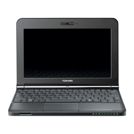
The Grand Tour Chapter 2 The Grand Tour This chapter identifies the various components of your computer. Become familiar with each component before you operate the computer. Front with the display closed The following figure shows the computer’s front with its display panel in the closed position. -
Page 25: System Indicators
The Grand Tour System indicators The LED system indicators for specific computer operations glow when those operations are in progress. System indicators Wireless The Wireless communication indicator glows communication amber when the Bluetooth and Wireless LAN functions are turned on. Only some models are equipped with Bluetooth and Wireless LAN functions. -
Page 26: Left Side
The Grand Tour Bridge media slot The Bridge media slot indicator glows green when the computer is accessing the Bridge media slot. Arrow Lock When the Arrow indicator lights green, you can use the dark gray labeled keys on the keypad overlay as cursor keys. - Page 27 The Grand Tour Microphone jack A standard 3.5 mm mini microphone jack enables connection of a microphone or other device for audio input. Headphone jack A standard 3.5 mm mini headphone jack enables connection of stereo headphones or other device for audio output.
-
Page 28: Right Side
The Grand Tour Right side The following figure shows the computer’s right side. 1. Universal Serial Bus (USB 2.0) port 2. DC IN 19V jack 3. Security lock slot The right side of the computer Universal Serial Bus Two Universal Serial Bus ports, which comply (USB 2.0) port with the USB 2.0 standard, are provided on the right side of the computer. -
Page 29: Underside
The Grand Tour Underside The following figure shows the underside of the computer. You should ensure that the display is closed before the computer is turned over to avoid causing any damage. 1. Memory module slot 4. Battery safety lock 2. -
Page 30: Front With The Display Open
The Grand Tour Battery safety lock Slide this latch into its "Unlock" position in order to release the battery pack ready for removal. Speaker The speaker emits sound generated by your software as well as audio alarms, such as low battery condition, generated by the system. - Page 31 The Grand Tour Web Camera LED The Web Camera LED glows when the Web Camera is working. Web Camera The Web Camera is a device that allows you to record video or take photographs with your computer. You can use it for video chatting or video conferencing using a communication tool.
-
Page 32: Ac Adaptor
The Grand Tour Keyboard indicators When the CAPS LOCK indicator glows, the keyboard will produce capitals when any letter is typed. 1. CAPS LOCK indicator Keypad indicators CAPS LOCK This indicator glows green when letter keys are locked into their uppercase format. AC adaptor The AC adaptor can automatically adjust to any voltage ranging from 100 to 240 volts and to a frequency of either 50 or 60 hertz, enabling you to use... - Page 33 Always use the TOSHIBA AC adaptor that was included with your computer, or use AC adaptors specified by TOSHIBA to avoid any risk of fire or other damage to the computer. Use of an incompatible AC adaptor could cause fire or damage to the computer possibly resulting in serious injury.
-
Page 34: Chapter 3 Getting Started
Getting Started Chapter 3 Getting Started This chapter provides basic information to start using your computer. It covers the following topics: ■ All users should be sure to read the section Starting up for the first time. ■ Be sure to read the enclosed Instruction Manual for Safety and Comfort for information on the safe and proper use of this computer. -
Page 35: Connecting The Ac Adaptor
■ Always use the TOSHIBA AC adaptor that was included with your computer or use AC adaptors specified by TOSHIBA to avoid any risk of fire or other damage to the computer. Use of an incompatible AC adaptor could cause fire or damage to the computer possibly resulting in serious injury. - Page 36 Getting Started 1. Connect the power cord to the AC adaptor. Connecting the power cord to the AC adaptor (2-pin plug) Connecting the power cord to the AC adaptor (3-pin plug) Either a 2-pin or 3-pin adaptor/cord will be included with the computer depending on the model.
-
Page 37: Opening The Display
Getting Started Opening the display The display panel can be opened to a wide range of angles for optimal viewing. While holding down the palm rest with one hand so that the main body of the computer is not raised, slowly lift the display panel - this will allow the angle of the display panel to be adjusted to provide optimum clarity. -
Page 38: Turning On The Power
Getting Started Turning on the power This section describes how to turn on the power - the Power indicator will then indicate the status. Please refer to the Monitoring of power condition section in Chapter 6, Power and Power-up Modes for more information. -
Page 39: Turning Off The Power
Getting Started Turning off the power The power can be turned off in one of three modes, either Shut Down Mode, Hibernation Mode or Suspend Mode. Shut Down Mode When you turn off the power in Shut Down Mode no data will be saved and the computer will boot to the operating system's main screen the next time it is turned on. -
Page 40: Starting Hibernation Mode
Getting Started Benefits of Hibernation Mode The Hibernation Mode feature provides the following benefits: ■ Saves data to the hard disk drive when the computer automatically shuts down because of a low battery condition. ■ You can return to your previous working environment immediately when you turn on the computer. - Page 41 Getting Started ■ Before entering Suspend Mode, be sure to save your data. ■ Do not install or remove a memory module while the computer is in Suspend Mode. The computer or the memory module could be damaged. ■ Do not remove the battery pack while the computer is in Suspend Mode (unless the computer is connected to an AC power source).
-
Page 42: Restarting The Computer
Getting Started Suspend Mode limitations Suspend Mode will not function under the following conditions: ■ Power is turned back on immediately after shutting down. ■ Memory circuits are exposed to static electricity or electrical noise. Restarting the computer Certain conditions require that you reset the computer, for example if: ■... -
Page 43: Restoring The Pre-Installed Software
Getting Started Restoring the pre-installed Software Depending on the model you purchased, different ways for restoring the pre-installed software are offered: ■ Restoring the pre-installed software from the Recovery hard disk drive ■ Creating recovery SDHC Card and restoring the pre-installed software from this SDHC card Restoring the pre-installed software from the recovery HDD A portion of the total hard disk drive space is configured as a hidden... - Page 44 Getting Started 3. If you want to restore the system to factory default, select Recovery to the out-of-box state. If you want to restore the system to sda3, select Recovery without changing hard drive partitions. If you want to restore to a custom sized partition, select Recovery to a custom sized partition.
- Page 45 Getting Started 4. When Recovery of the out-of-box state or Recovery to a custom sized partition option is selected, the message "All partitions will be deleted and you will lose all data on the hard drive." shows up. When Recovery without changing hard drive partitions is selected, the message "The first partition will be deleted and you will lose all data on the partition."...
- Page 46 Getting Started 6. If the creation of the partitions is completed, the recovery process starts. This process will take some minutes. 7. The following message will displayed if the Recovery of the Pre- installed software is completed correctly. Click the Finish button to restart the computer and the setup of Ubuntu.
-
Page 47: Creating Recovery Sdhc Card
Please verify the SD card slot supports the blank SDHC Card you choose. 2. Turn on your computer to open Ubuntu Linux. 3. Insert the SDHC Card into the SD Card Slot. 4. Click the TOSHIBA Recovery Media Creator icon on the Linux Ubuntu desktop. User’s Manual 3-14... -
Page 48: Restoring The Pre-Installed Software From The Sdhc Card
Getting Started 5. After TOSHIBA Recovery Media Creator starts, select the SDHC Card and then click the Start button. 6. Follow the on-screen instructions. If the Error message 0x10006 appears, make sure that the SDHC Card is unlocked. Restoring the pre-installed software from the SDHC Card If pre-installed files are damaged, use your created Recovery SDHC Card to restore them. - Page 49 Getting Started 5. Select USB Memory using the arrow keys and press Enter. 6. Wait for the system to boot up from the Recovery SDHC Card and the recovery screen appears. 7. Follow the on-screen instructions. 8. After the recovery has been completed, keep the Recovery SDHC Card for future use.
-
Page 50: Chapter 4 Operating Basics
Operating Basics Chapter 4 Operating Basics This chapter describes the basic operations of your computer and highlights the precautions that should be taken when using it. Using the Touch Pad To use the Touch Pad, simply touch and move your fingertip across it in the direction you want the on-screen pointer to go. -
Page 51: Usb Sleep And Charge Function
Operating Basics You can also tap the Touch Pad to perform functions similar to those of the left button on a standard mouse. Click: Tap once Double-click: Tap twice Drag and drop: Tap to select the item(s) you want to move, leave your finger on the Touch Pad after the second tap and then move the item(s) to their new destination. -
Page 52: Using The Web Camera
Operating Basics Using the web camera Built-in web camera is provided with some models.This section describes the bundled webcam utility, which can capture still and video images. The web camera will not auto-run when Linux starts. Ensure that you remove the protective plastic film that covers the Web Camera before using it. -
Page 53: Using The Software
Operating Basics Using the software The web camera software is pre-configured to start when you turn on Ubuntu. If you need to restart it go to Favorites Cheese. 1. Photo 4. Effect 2. Video 5. Edit 3. Take a photo/Start recording 6. -
Page 54: Using The Microphone
Operating Basics Photo Press "Take a photo" function to capture the images. Video Press "Start recording" function to start recording. Click on final time to stop recording and see a preview of the video. Effect Choose images to be displayed on the capture screen. -
Page 55: Bluetooth Wireless Technology
■ TOSHIBA is not liable for the loss of data due to eavesdropping or illegal access through the wireless LAN and the damage thereof. Bluetooth wireless technology Bluetooth™... -
Page 56: Wireless Communication Indicator
Operating Basics Security Two advanced security mechanisms ensure a high level of security: ■ Authentication prevents access to critical data and makes it impossible to falsify the origin of a message. ■ Encryption prevents eavesdropping and maintains link privacy. Enable/Disable Wireless communication with hot key You can enable or disable Wireless communication (Wireless LAN and Bluetooth) functions with hot keys (FN + F8). -
Page 57: Wireless Wan
Limitation of Liability While TOSHIBA has made every effort at the time of publication to ensure the accuracy of the information herein, product specifications, configurations, system component/options availability are all subject to change without notice. - Page 58 Operating Basics Installing a SIM Card The SIM card slot is located under the battery pack of the computer. You can install and remove one SIM card in the slot. To install the SIM card, follow the steps below: 1. Shut down the computer - ensure that the Power indicator is off. 2.
-
Page 59: Disabling Or Enabling Wireless Devices
Operating Basics 8. Turn your computer over. Sim Card ■ Never allow metal objects, such as screws, staples and paper clips, to enter the computer. Foreign metal objects can create a short circuit, which can cause computer damage and fire, possibly resulting in serious injury. -
Page 60: Regulatory Information
Operating Basics Enabling GPS Your system includes built-in GPS (Global Positioning System) functionality. GPS is a global satellite-based navigation system. It uses a constellation of a number of satellites that transmit precise microwave signals. That enables GPS receivers to determine their current locations, the time and their velocity. -
Page 61: Lan
Operating Basics The computer has built-in support for Ethernet LAN (10 megabits per second, 10BASE-T) and Fast Ethernet LAN (100 megabits per second, 100BASE-TX). This section describes how to connect/disconnect to a LAN. Do not install or remove a memory module while Wake-up on LAN is enabled. -
Page 62: Disconnecting The Lan Cable
Operating Basics 1. LAN jack 2. LAN cable Connecting the LAN cable 3. Plug the other end of the cable into a LAN hub connector or router. Check with your LAN administrator and hardware or software vendor before using or configuring a network connection. When the computer is exchanging data with the LAN, the LAN Active indicator glows amber. -
Page 63: Cleaning The Computer
Operating Basics Cleaning the computer To help ensure long, trouble-free operation, keep the computer free of dust and dirt, and use care with all liquids around it. ■ Be careful not to spill liquids into the computer. If the computer does get wet, turn the power off immediately and let the computer dry completely - in these circumstance you should get the computer inspected by an authorized service provider in order to assess the scope of any... -
Page 64: Moving The Computer
Operating Basics Moving the computer While the computer is designed for rugged durability you should exercise a few simple precautions when moving it in order to help ensure trouble-free operation. ■ Make sure all disk activity has ended before moving the computer - check that the HDD and other indicators on the front of the computer are off. -
Page 65: Chapter 5 The Keyboard
The Keyboard Chapter 5 The Keyboard The computer's keyboard layouts are compatible with a 104/105-key enhanced keyboard - by pressing some keys in combination, all of the 104/105-key enhanced keyboard functions can be performed on the computer. The number of keys available on your keyboard will depend on which country/region your computer is configured for, with keyboards being available for numerous languages. -
Page 66: Function Keys: F1
Soft keys: FN key combinations The FN (function) is unique to TOSHIBA computers and is used in combination with other keys to form soft keys. Soft keys are key combinations that enable, disable or configure specific features. -
Page 67: Hot Keys
The Keyboard This computer's keyboard is designed to provide all the features of the 104-key enhanced keyboard except that of Keys. Since the keyboard is smaller and has fewer keys, some of the enhanced keyboard functions must be simulated using two keys instead of one on the larger keyboard. - Page 68 The Keyboard Suspend: Pressing FN + F3 switches the system to Suspend mode (Only active when enable Suspend in Power Manager). Hibernate: Pressing FN + F4 switches the system to Hibernation mode (Only active when enable Hibernate in Power Manager). Output: Pressing FN + F5 changes the active display device.
-
Page 69: Linux Special Keys
The Keyboard Touch Pad: Pressing FN + F9 enables or disables the Touch Pad function. Zoom: Pressing FN + Space changes the display resolution. Zooming (reduce): Pressing FN + 1 reduces the font sizes within one of the supported application windows (Adobe Reader, Open office, Fire fox). Zooming (enlarge): Pressing FN + 2 enlarges the font sizes within one of the supported application windows (Adobe Reader, Open office, Fire fox). -
Page 70: Keypad Overlay
The Keyboard Keypad overlay Your computer's keyboard does not have a separate numeric keypad but includes a numeric keypad overlay which functions like one - this is located in the center of the keyboard with the relevant keys having grey letters at their front edge. -
Page 71: Temporarily Changing Modes
The Keyboard Temporarily using normal keyboard (overlay on) While using the overlay, you can temporarily access the normal keyboard functions without having to turn the overlay off: 1. Hold FN and press any other key - this key will operate as if the overlay were off. -
Page 72: Chapter 6 Power And Power-Up Modes
Power and Power-up Modes Chapter 6 Power and Power-up Modes The computer's power resources include the AC adaptor and internal batteries. This chapter gives details on making the most effective use of these resources including charging and changing batteries, tips for saving battery power, and power-up modes. -
Page 73: Power Indicators
Power and Power-up Modes Power on Power off (no operation) AC adaptor Battery charge • Operates is above low • LED: Battery off connected battery trigger • DC IN off point Battery charge • Operates is below low • LED: Battery blinking battery trigger amber point... -
Page 74: Dc In Indicator
Power and Power-up Modes DC IN indicator Check the DC IN indicator to determine the power status with the AC adaptor connected - the following indicator conditions should be noted: Green Indicates the AC adaptor is connected and is correctly supplying power to the computer. No light Under any other conditions, the indicator does not light. -
Page 75: Real Time Clock Battery
Press <F1> to resume, <F2> to Setup. The computer's RTC battery is a lithium battery and should be replaced only by your dealer or by a TOSHIBA service representative. The battery can explode if not properly replaced, used, handled or disposed of. -
Page 76: Charging The Batteries
The battery pack is lithium ion battery, which can explode if not replaced, used, handled or disposed of properly. Dispose of the battery as required by local ordinances or regulations. Use only batteries recommended by TOSHIBA as replacements. ■ Charge the battery pack only in an ambient temperature between 5 and 35 degrees Celsius. -
Page 77: Battery Charging Notice
Power and Power-up Modes Time The following table shows the approximate time required to fully charge a discharged battery. Battery type Power on Power off Battery Pack about 12 or longer about 4 or longer (3 cell) Battery Pack about 12 or longer about 6 or longer (6 cell) RTC battery... -
Page 78: Monitoring Battery Capacity
Power and Power-up Modes Monitoring battery capacity Remaining battery power can be monitored by a battery icon on notification area. ■ You should wait at least 16 seconds after turning on the computer before trying to monitor the remaining operating time. This is because the computer needs this time to check the battery's remaining capacity and then calculate the remaining operating time, based on this together with the current power consumption. -
Page 79: Retaining Data With Power Off
Power and Power-up Modes Retaining data with power off When you turn off your computer with fully charged batteries, the batteries retain data for the following approximate time periods. Battery type State and Retention Time Battery pack 1 day for 6 cell, 0.5 day for 3 cell (Standby mode) 30 days for 3 cell, 60 days for 6 cell (shut down mode) RTC battery... -
Page 80: Replacing The Battery Pack
Power and Power-up Modes Replacing the battery pack Please be aware that the battery pack is classified as a consumable item. The operating life of the battery pack will gradually reduce through repeated charging and discharging, and will need to be replaced when it reaches the end of its operating life. - Page 81 Power and Power-up Modes 1. Battery safety lock 3. Battery pack 2. Battery release latch Releasing the battery pack (1) 6. Slide and hold the battery release latch (1) to disengage the battery pack and then remove it from the computer (2). Releasing the battery pack (2) User’s Manual 6-10...
-
Page 82: Power-Up Modes
Power and Power-up Modes To install a battery, follow the steps as detailed below: 1. Insert the battery pack as far as it will go into the computer (1). 2. Ensure that the battery pack is securely in place and the battery safety lock (2) is in its position. -
Page 83: System Auto Off
Power and Power-up Modes Hot keys You can use the FN + F3 hot key to enter Suspend Mode or FN + F4 to enter Hibernation Mode - please refer to Chapter 5, The Keyboard further details. Panel power on/off You can set up your computer so that power is turned off automatically when you close the display panel, and turned on again when you open it. -
Page 84: Chapter 7 Bios Setup And Passwords
BIOS Setup and Passwords Chapter 7 BIOS Setup and Passwords This chapter explains how to use BIOS to set up user and supervisor passwords. Accessing BIOS Setup Menu To start the utility, please press F2 to enter the BIOS Setup Menu when booting up the computer. -
Page 85: Set User Password
BIOS Setup and Passwords Password User Password/Supervisor Password Select Set User Password/Set Supervisor Password and press Enter, then the following message is shown: Set User Password Enter New Password Confirm New Password If there is an old password set, setup will display the following and require that the existing password is entered first: Set User Password Enter Current Password... -
Page 86: Boot Priority
BIOS Setup and Passwords Starting the computer by password If you have already registered a password, please enter the password manually to start the computer: To enter a password manually, follow these steps: 1. Turn on the power as described in Chapter 3, Getting Started. -
Page 87: Usb Sleep And Charge
BIOS Setup and Passwords USB Sleep and Charge Your computer can supply USB bus power (DC5V) to the USB port even when the power of the computer is turned OFF. "Power OFF" includes Suspend Mode, Hibernation Mode or shutdown state.This function can be used for ports that support the USB Sleep and Charge function (hereinafter called "compatible ports"). - Page 88 BIOS Setup and Passwords Enabled (Mode1) Enables USB Sleep and Charge function. Enabled (Mode2) Enables USB Sleep and Charge function. Enabled (Mode3) Enables USB Sleep and Charge function. Enabled (Mode4) Enables USB Sleep and Charge function. Disabled Disables USB Sleep and Charge function (Default).
-
Page 89: Chapter 8 Optional Devices
Optional Devices Chapter 8 Optional Devices Optional devices can expand the computer's capabilities and its versatility. This chapter describes the connection or installation of the following devices: To connect optional devices (such as USB device or External monitor) to the computer, be sure to check the shape and orientation of the connector before connecting. -
Page 90: Bridge Media Slot
Optional Devices Bridge media slot The computer is equipped with a Bridge media slot that can accommodate some kinds of memory media with various memory capacities so that you can easily transfer data from devices, such as digital cameras and Personal Digital Assistants. -
Page 91: Additional Memory Module
Optional Devices ■ The SD memory card logo is ( ■ The SDHC memory card logo is ( ■ The maximum capacity of SD memory cards is 2GB. The maximum capacity of SDHC memory cards is 16G. Card Type Capacities 8MB, 16MB, 32MB, 64MB, 128MB, 256MB, 512MB, 1GB, 2GB SDHC... - Page 92 Optional Devices ■ Use only memory modules approved by TOSHIBA. ■ Do not try to install or remove a memory module under the following conditions. a. The computer is turned on. b. The computer was shut down in either Suspend or Hibernation Mode.
- Page 93 Optional Devices 1. Memory module cover Removing the memory module cover 4. Align the notch of the memory module with that of the memory module slot and gently insert the module into the slot at about a 30 degree angle before gently pressing until the latches on either side snap into place.
- Page 94 Optional Devices ■ Never allow metal objects, such as screws, staples and paper clips, to enter the computer or keyboard. Foreign metal objects can create a short circuit, which can cause computer damage and fire, possibly resulting in serious injury. ■...
-
Page 95: Battery Packs
Optional Devices Removing a memory module To remove the memory module, follow the steps as detailed below: 1. Turn the computer off and remove all cables connected to the computer. 2. Turn the computer upside down and remove the battery pack (refer to Chapter 6, Power and Power-up Modes.) -
Page 96: External Monitor
Optional Devices External monitor An external analog monitor can be connected to the computer's external monitor port, with the computer supporting WSVGA video mode. In order to connect a monitor, follow the steps as detailed below: 1. Connect the monitor cable to the external monitor port. 1. -
Page 97: Security Lock
Optional Devices Security lock A security locks enable you to anchor your computer to a desk or other heavy object in order to help prevent unauthorized removal or theft. The computer has a security lock slot on its right side into which you can attach one end of the security cable, while the other end attaches to a desk or similar object. -
Page 98: Troubleshooting
Troubleshooting Chapter 9 Troubleshooting TOSHIBA designed the computer for durability. However, should problems occur, following the procedures in this chapter can help to determine the cause. All readers should become familiar with this chapter. Knowing what might go wrong can help prevent problems from occurring. -
Page 99: Analyzing The Problem
Troubleshooting ■ Inspect all connecting cables for loose wires and all connectors for loose pins. ■ Check that your diskette is correctly inserted and that the diskette’s write protect tab is correctly set. Make notes of your observations and keep them in a permanent error log. This will help you describe your problems to your dealer. -
Page 100: Hardware And System Checklist
When the computer starts up, the self-test will be run automatically, and the following will be displayed: TOSHIBA Leading Innovation>>> This message remains on the screen for a few seconds. If the self test is successful, the computer tries to load the operating system. -
Page 101: Overheating Power Down
Troubleshooting Power When the computer is not plugged into an AC adaptor, the battery pack is the primary power source. However, your computer has a number of other power resources, including intelligent power supply and Real Time Clock battery. These resources are interrelated and any one could affect apparent power problems. - Page 102 Troubleshooting Problem Procedure Check whether the battery is hot or cold to the touch. If the battery is too hot or too cold, it will not charge properly. Make it reach room temperature. Unplug the AC adaptor and remove the battery to make sure the terminals are clean.
-
Page 103: Hard Disk Drive
Troubleshooting Problem Procedure Output to screen is Make sure the software you are using is not garbled remapping the keyboard. Remapping involves reassigning the meaning of each key. See your software’s documentation. If you are still unable to use the keyboard, consult your dealer LCD panel Apparent LCD problems may be related to the computer’s setup. -
Page 104: Touch Pad
Troubleshooting Pointing device If you are using a USB mouse, also refer to the section in this chapter and to your mouse documentation. Touch Pad Problem Procedure On-screen pointer The system might be busy. If the pointer is does not respond to shaped as an hourglass, wait for it to resume its Touch Pad operation normal shape and try again to move it. -
Page 105: Sound System
Troubleshooting SD/MultiMedia Card Refer also to Chapter 8, Optional Devices. Problem Procedure Memory card error Reseat the memory card to make sure it is firmly occurs connected. Check the card’s documentation. You cannot write to Make sure the card is not write protected. the memory card You cannot read a file Make sure the target file is on the memory card inserted in the slot. - Page 106 Troubleshooting Refer also to your USB device’s documentation. Problem Procedure USB device does not Check for a firm cable connection between the work USB ports on the computer and the USB device. Make sure the USB device drivers are properly installed.
-
Page 107: Toshiba Support
If problems persist, contact your dealer. TOSHIBA support If you require any additional help using your computer or if you are having problems operating the computer, you may need to contact TOSHIBA for additional technical assistance. Before you call Some problems you experience may be related to software or the operating system so it is important that you investigate other sources of assistance first. -
Page 108: Where To Write
Troubleshooting Where to write If you are still unable to solve the problem and suspect that it is hardware related, write to TOSHIBA at the location listed in the enclosed warranty booklet or visit http://www.toshiba-europe.com on the Internet. User’s Manual... -
Page 109: Cpu*1
5°C to 30°C (41°F to 86°F) or >25°C (77°F) at high altitude (all temperature references are approximate and may vary depending on the specific computer model - please refer to your PC documentation or visit the Toshiba website at http://www.pcsupport.toshiba.com for details). -
Page 110: Battery Life
Published battery life numbers are achieved on select models and configurations tested by Toshiba at the time of publication. Recharge time varies depending on usage. Battery may not charge while computer is consuming full power. -
Page 111: Copy Protection
Legal Footnotes Wireless LAN The transmission speed over the wireless LAN and the distance over which wireless LAN can reach may vary depending on surrounding electromagnetic environment, obstacles, access point design and configuration, and client design and software/hardware configurations. The actual transmission speed will be lower than the theoretical maximum speed. - Page 112 Appendixes Appendixes Table of Contents Specifications................A-1 Appendix A Display Controller................. B-1 Appendix B Wireless LAN................. C-1 Appendix C AC Power Cord and Connectors..........D-1 Appendix D If your computer is stolen............E-1 Appendix E User’s Manual Appendixes-1...
-
Page 113: Appendix A Specifications
Specifications Appendix A Specifications This appendix summarizes the computer’s technical specifications. Physical Dimensions Size Size With 3 cell Battery 263.0(w) × 192.3(d) × 25.4(front) × 30.8(rear) millimeters (not including parts that extend beyond the main body) With 6 cell Battery 263.0(w) × 211.5(d) × 25.4(front) × 30.8(rear) millimeters (not including parts that extend beyond the main body) Environmental requirements... -
Page 114: Appendix B Display Controller
Display Controller Appendix B Display Controller Display controller The display controller interprets software commands into hardware com- mands that turn particular pixels on or off. The controller is an advanced Video Graphics Array (VGA) that provides Super VGA (SVGA) and Extended Graphics Array (XGA) support for the internal LCD and external monitors. -
Page 115: Appendix C Wireless Lan
Wireless LAN Appendix C Wireless LAN This appendix is intended to help you get your Wireless LAN network up and running, with a minimum of parameters. Card Specifications Form Factor ■ Mini Card Compatibility ■ IEEE 802.11 Standard for Wireless LANs ■... - Page 116 Subject to the radio regulations that apply in your country/region, your Wireless LAN card may support a different set of 2.4 GHz channels. Consult your Authorized Wireless LAN or TOSHIBA Sales office for infor- mation about the radio regulations that apply in your country/region.
-
Page 117: Appendix Dac Power Cord And Connectors
AC Power Cord and Connectors Appendix D AC Power Cord and Connectors The AC input plug of power cord must be compatible with various interna- tional AC power outlets. Power cords need to meet the local standards and the specifications listed as below: Length: Minimum 1.7 meters Wire size:... - Page 118 AC Power Cord and Connectors The following illustrations show the plug shapes for USA, Australia Can- ada, United Kingdom, Europe, and China. United Kingdom UL approved BS approved Australia Europe AS approved Approved by the appropriate agency Canada China CSA approved CCC approved User’s Manual...
-
Page 119: Appendix E If Your Computer Is Stolen
What is your address, phone, and fax number? To register the theft on paper, please follow these procedures: ■ Fill in the TOSHIBA Theft Registration form (or a copy of it) below. ■ Attach a copy of your receipt showing where your computer was purchased. -
Page 120: Toshiba Theft Registration
If your computer is stolen TOSHIBA Theft Registration Send to: TOSHIBA Europe GmbH Technical Service and Support Leibnizstr. 2 93055 Regensburg Germany Fax number: +49 (0) 941 7807 921 Country stolen: Machine type: (e.g. TOSHIBA mini NB200 series) Model number: (e.g. - Page 121 Glossary Glossary The terms in this glossary cover topics related to this manual. Alternate naming is included for reference. Abbreviations AACS: advanced access content system AC: Alternating current ACPI: Advanced Configuration and Power Interface ASCII: American Standard Code for Information Interchange BIOS: basic input/output system bps: bits per second CD: compact disc...
- Page 122 Glossary GB: gigabyte HDD: hard disk drive HD+: High Definition Plus IDE: integrated drive electronics IEEE: Institute of Electrical and Electronics Engineers I/O: input/output IrDA: Infrared Data Association IRQ: interrupt request KB: kilobyte LAN: local area network LCD: liquid crystal display LED: light emitting diode MB: megabyte MMC: multi media card...
- Page 123 Glossary adaptor: A device that provides a compatible connection between two units. For example, the computer's internal display adapter receives information from the software and translates it into images on the screen. An adapter can take a number of forms, from a microprocessor to a simple connector: An intelligent adapter (one that is capable of doing some processing) may also be called a controller.
- Page 124 Glossary board: A circuit board. An internal card containing electronic components, called chips, which perform a specific function or increase the capabilities of the system. boot: Short for bootstrap. A program that starts or restarts the computer. The program reads instructions from a storage device into the computer’s memory.
- Page 125 Glossary click: To press and release the pointing device's primary button without moving the pointing device. In the Linux operating system, this refers to the pointing device's left button, unless otherwise stated. See also double-click. CMOS: Complementary Metal-Oxide Semiconductor. An electronic circuit fabricated on a silicon wafer that requires very little power.
- Page 126 Glossary data: Information that is factual, measurable or statistical that a computer can process, store, or retrieve. data bits: A data communications parameter controlling the number of bits (binary digits) used to make up a byte. If data bits = 7 the computer can generate 128 unique characters.
- Page 127 Glossary DVB-T (Digital Video Broadcasting - Terrestrial): Also known as terrestrial digital TV. Digital TV broadcasting standard. DVD-R (+R, -R): A Digital Versatile Disc Recordable disc can be written once and read many times. The DVD-R drive uses a laser to read data from the disc.
- Page 128 Glossary fast infrared: An industry standard that enables cableless infrared serial data transfer at speeds of up to 4 Mbps. file: A collection of related information; a file can contain data, programs, or both. fingerprint sensor: The fingerprint sensor compares and analyzes the unique characteristics in a fingerprint.
- Page 129 Glossary hardware: The physical electronic and mechanical components of a computer system: typically, the computer itself, external disk drives, etc. See also software and firmware. hertz: A unit of wave frequency that equals one cycle per second. host computer: The computer that controls, regulates, and transmits information to a device or another computer.
- Page 130 Glossary K: Taken from the Greek word kilo, meaning 1000; often used as equivalent to 1024, or 2 raised to the 10th power. See also byte and kilobyte. keyboard: An input device containing switches that are activated by manually pressing marked keys. Each keystroke activates a switch that transmits a specific code to the computer.
- Page 131 Glossary menu: A software interface that displays a list of options on the screen. Also called a screen. microprocessor: A hardware component contained in a single integrated circuit that carries out instructions. Also called the central processing unit (CPU), one of the main parts of the computer. mode: A method of operation, for example, the Shut Down Mode, Suspend Mode or the Hibernation Mode.
- Page 132 The electrical connection through which the computer sends and receives data to and from devices or other computers. Power Saver: A TOSHIBA utility that lets you set the parameters for various power-saving functions. program: A set of instructions a computer can execute that enables it to achieve a desired result.
- Page 133 A Class A device is sufficient for office use. Class B provides a more stringent classification for home equipment use. TOSHIBA portable computers comply with Class B computing device regulations. Random Access Memory (RAM): Volatile memory that can be written to as well as read.
- Page 134 TFT display: A liquid crystal display (LCD) made from an array of liquid crystal cells using active-matrix technology with thin film transistor (TFT) to drive each cell. Touch Pad: A pointing device integrated into the TOSHIBA computer palm rest. USB: Universal Serial Bus. This serial interface lets you communicate with several devices connected in a chain to a single port on the computer.
- Page 135 Glossary warm start: Restarting or resetting a computer without turning it off. ® Wi-Fi : A registered trademark term of the Wi-Fi Alliance that stands for Wireless Fidelity, and is another term for the communication protocol to permit an Ethernet connection using wireless communication components.
- Page 136 Monitoring capacity, 6-7 Equipment checklist, 1-1 real time clock, 1-3, 6-4 External monitor, 1-4, 2-3, 8-8 types, 6-3 Battery Charger, 8-7 FN + 1 (TOSHIBA Zooming Battery pack, 1-3, 2-6 Utility reduce), 5-5 additional, 8-7 FN + 2 (TOSHIBA Zooming replacing, 6-9...
- Page 137 Lock, 5-3 jack, 2-4 Mute, 5-3 Output, 5-4 Memory, 1-2 Power Plan, 5-3 expansion, 1-7 Suspend, 5-4 installing, 8-4 TOSHIBA Zooming Utility removing, 8-7 (enlarge), 5-5 Modem TOSHIBA Zooming Utility problems, 9-9 (reduce), 5-5 Monitor Touch Pad, 5-5 automatic power off, 1-6...
- Page 138 3-7 Hard disk drive, 9-6 System automatic, 1-6 Hardware and system checklist, 9-3 TOSHIBA support, 9-10 Keyboard, 9-5, 9-6 TOSHIBA Theft Registration, E-2 LAN, 9-9 Touch Pad, 1-3 Memory Stick/Memory Stick using, 4-1 PRO/Memory Stick PRO Duo, 9-8 Overheating power down, 9-4...
Need help?
Do you have a question about the mini NB200 series and is the answer not in the manual?
Questions and answers