Toshiba NB250 series User Manual
Hide thumbs
Also See for NB250 series:
- Maintenance manual (222 pages) ,
- User manual (130 pages) ,
- Maintenance manual (222 pages)
Table of Contents
Advertisement
Advertisement
Table of Contents

Related Manuals for Toshiba NB250 series


Summary of Contents for Toshiba NB250 series
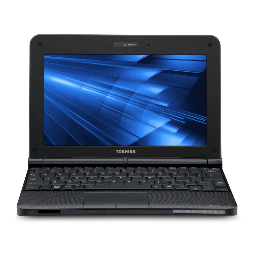
- Page 1 TOSHIBA NB250/NB255 series User's Manual...
-
Page 2: Copyright
Copyright © 2010 by TOSHIBA Corporation. All rights reserved. Under the copyright laws, this manual cannot be reproduced in any form without the prior written permission of TOSHIBA. No patent liability is assumed, with respect to the use of the information contained herein. -
Page 3: Fcc Information
Only peripherals complying with the FCC class B limits may be attached to this equipment. Operation with non-compliant peripherals or peripherals not recommended by TOSHIBA is likely to result in interference to radio and TV reception. Shielded cables must be used between the external devices and the computer’s external monitor port, Universal Serial Bus... -
Page 4: Eu Declaration Of Conformity
This product is carrying the CE-Mark in accordance with the related European Directives. Responsible for CE-Marking is TOSHIBA Europe GmbH, Hammfelddamm 8, 41460 Neuss, Germany. The complete and official EU Declaration of Conformity can be found on TOSHIBA’s web site http://epps.toshiba-teg.com on the Internet. CE compliance... -
Page 5: Vcci Class B Information
Note that Canadian Department of Communications (DOC) regulations provide, that changes or modifications not expressly approved by TOSHIBA Corporation could void your authority to operate this equipment. This Class B digital apparatus meets all requirements of the Canadian Interference-Causng Equipment Regulations. -
Page 6: Following Information Is Only Valid For Eu-Member States
For more detailed information about the collection and recycling programmes available in your country, please visit our website (http://eu.computers.toshiba-europe.com) or contact your local city office or the shop where you purchased the product. Disposal of batteries and/or accumulators The crossed out wheeled dust bin symbol indicates that batteries and/or accumulators must be collected and disposed of separately from household waste. -
Page 7: Disposing Of The Computer And The Computer's Batteries
The new European Union (EU) chemical regulation, REACH (Registration, Evaluation, Authorization and Restriction of Chemicals), entered into force on 1 June 2007. TOSHIBA will meet all REACH requirements and is committed to provide our customers with information about the chemical substances in our products according to REACH regulation. -
Page 8: Precautions
Precautions CAUTION: This appliance contains a laser system and is classified as a “CLASS 1 LASER PRODUCT.” To use this model properly, read the instruction manual carefully and keep this manual for your future reference. In case of any trouble with this model, please contact your nearest “AUTHORIZED service station.”... -
Page 9: Table Of Contents
Special features ......... . 1-8 TOSHIBA Value Added Package ......1-10 Utilities and Applications. - Page 10 TOSHIBA Disc Creator ........
- Page 11 TOSHIBA support ........
-
Page 12: Preface
This manual tells how to set up and begin using your TOSHIBA NB250/NB255 computer. It also provides detailed information on configuring your computer, basic operations and care, using optional devices and troubleshooting. -
Page 13: Conventions
Preface Chapter 5, Keyboard, describes special keyboard functions including the keypad overlay and hot keys. Chapter 6, Power and Power-up Modes, gives details on the computer’s power resources and battery save modes. Chapter 7, HW Setup and Passwords, explains how to configure the computer using the HW Setup program. - Page 14 Preface When procedures require an action such as clicking an icon or entering text, the icon's name or the text you are to type in is represented in the typeface you see to the left. Display Names of windows or icons or text generated by the computer that appear on its display screen are presented in the type face you see to the left.
-
Page 15: General Precautions
General Precautions TOSHIBA computers are designed to optimize safety, minimize strain and withstand the rigors of portability. However, certain precautions should be observed to further reduce the risk of personal injury or damage to the computer. Be certain to read the general precautions below and to note the cautions included in the text of the manual. -
Page 16: Creating A Computer-Friendly Environment
General Precautions Creating a computer-friendly environment Place the computer on a flat surface that is large enough for the computer and any other items you are using, such as a printer. Leave enough space around the computer and other equipment to provide adequate ventilation. -
Page 17: Pressure Or Impact Damage
General Precautions Pressure or impact damage Do not apply heavy pressure to the computer or subject it to any form of strong impact as this can damage the computer's components or otherwise cause it to malfunction. Mobile phones Please be aware that the use of mobile phones can interfere with the audio system. -
Page 18: Introduction
Some of the features described in this manual may not function properly if you use an operating system that was not pre-installed by TOSHIBA. Equipment checklist Carefully unpack your computer, taking care to save the box and packaging materials for future use. - Page 19 TOSHIBA Assist ■ TOSHIBA eco Utility ■ Online Manual ■ TOSHIBA NB250/NB255 series User's Manual (This manual) Documentation ■ TOSHIBA NB250/NB255 Series User Information Guide ■ Instruction Manual for Safety and Comfort If any of the items are missing or damaged, contact your dealer immediately.
-
Page 20: Features
Built-in Your computer is equipped with one processor and processor type varies depending on model. To check which type of processor is included in your model, open the TOSHIBA PC Diagnostic Tool Utility by clicking Start All programs TOSHIBA Utilities PC Diagnostic Tool. -
Page 21: Pointing Device
Introduction Disks Hard disk drive This computer supports SATA 3.0Gbps and is equipped with one of the following hard disk drive (HDD) types. The capacity of each hard disk drive model is different. ■ ■ 160GB ■ 250GB Please note that part of the hard disk drives overall capacity is reserved as administration space. - Page 22 You can use it for video chatting or video conferences using a communication tool such as Windows Live Messenger. TOSHIBA Web Camera Application will help you to add various video effects to your video or photograph.
- Page 23 Introduction Headphone jack This jack lets you connect speakers or a stereo headphone. When you connect an external speaker or headphones, the internal speaker is automatically disabled. Microphone jack A 3.5mm mini microphone jack enables connection of a three-conductor mini jack for stereo microphone input, and connection of a stereo device for audio input.
- Page 24 Windows 7 is available. Refer to the preinstalled Software section at the front of this chapter. TOSHIBA Utilities A number of utilities and drivers are preinstalled to make your computer more convenient to use. Refer to the Utilities and Applications section in this chapter.
-
Page 25: Special Features
Introduction Special features The following features are either unique to TOSHIBA computers or are advanced features which make the computer more convenient to use. Access each function using the following procedures. *1 To access the Power Options, click Start Control Panel... - Page 26 Introduction This feature lets you configure the computer in Battery save mode order to save battery power. This can be specified in the Power Options. Low battery When battery power is exhausted to the point that automatic computer operation cannot be continued, the system automatically enters Hibernation Mode Hibernation Mode and shuts itself down.
-
Page 27: Toshiba Value Added Package
TOSHIBA Value Added Package TOSHIBA Flash The TOSHIBA Flash Cards provide a quick way Cards to modify selected system functions and to launch applications. ■... -
Page 28: Utilities And Applications
You may not have all the utilities or applications listed below depending on the model you purchased. TOSHIBA ConfigFree TOSHIBA ConfigFree is a suite of utilities that improve the ease and control of communication devices and network connections, help in the... -
Page 29: Options
1GB or 2GB memory module can be installed in the computer's memory slot. This computer can be equipped with an optional 2GB memory module validated by TOSHIBA. The available optional memory depends on the authorization situation of TOSHIBA. -
Page 30: Front With The Display Closed
Chapter 2 The Grand Tour This chapter identifies the various components of your computer. Become familiar with each component before you operate the computer. Front with the display closed The following figure shows the computer’s front with its display panel in the closed position. -
Page 31: System Indicators
The Grand Tour System indicators The LED system indicators for specific computer operations glow when those operations are in progress. Figure 2-2 System indicators Wireless The Wireless communication indicator glows communication amber when the Wireless LAN function is turned on. Only some models are equipped with Wireless LAN function. -
Page 32: Left Side
The Grand Tour Arrow Lock When the Arrow indicator lights green, you can use the dark gray labeled keys on the keypad overlay as cursor keys. Numeric Lock When the Numeric Lock indicator glows green, you can use the dark gray labelled keys on the keypad overlay for numeric input. - Page 33 The Grand Tour Headphone jack A standard 3.5 mm mini headphone jack enables connection of stereo headphones or other device for audio output. When you connect headphones, the internal speaker is automatically disabled. LAN jack This jack lets you connect to a LAN. The adaptor has built-in support for Ethernet LAN (10 megabits per second, 10BASE-T) and Fast Ethernet LAN (100 megabits per second,...
-
Page 34: Right Side
The Grand Tour Right side The following figure shows the computer’s right side. 1. Universal Serial Bus (USB 2.0) port 2. DC IN 19V jack 3. Security lock slot Figure 2-4 The right side of the computer Universal Serial Bus Two Universal Serial Bus ports, which comply (USB 2.0) port with the USB 2.0 standard, are provided on the... -
Page 35: Underside
The Grand Tour Underside The following figure shows the underside of the computer. You should ensure that the display is closed before the computer is turned over to avoid causing any damage. 1. Memory module slot 2. Battery release latch 3. - Page 36 The Grand Tour Battery pack The battery pack provides power to the computer when the AC adaptor is not connected. For more detailed information on the use and operation of the battery pack please refer to Chapter 6, Power and Power-up Modes.
-
Page 37: Front With The Display Open
The Grand Tour Front with the display open This section shows the computer with the display panel open. In order to open the display, lift the display panel up and position it at a comfortable viewing angle for you. 1. Web Camera LED 2. - Page 38 You can use it for video chatting or video conferencing using a communication tool such as Windows Live Messenger. TOSHIBA Web Camera Application will help you to add various video effects to your video or photograph.
-
Page 39: Keyboard Indicators
The Grand Tour Keyboard indicators When the CAPS LOCK indicator glows, the keyboard will produce capitals when any letter is typed. 1. CAPS LOCK indicator Figure 2-8 Keypad indicators CAPS LOCK This indicator glows green when letter keys are locked into their uppercase format. User’s Manual 2-10... -
Page 40: Ac Adaptor
Always use the TOSHIBA AC adaptor that was included with your computer, or use AC adaptors specified by TOSHIBA to avoid any risk of fire or other damage to the computer. Use of an incompatible AC adaptor could cause fire or damage to the computer possibly resulting in serious injury. -
Page 41: Chapter 3 Getting Started
Chapter 3 Getting Started This chapter provides basic information to start using your computer. It covers the following topics: ■ All users should be sure to read the section Starting up for the first time. ■ Be sure to read the enclosed Instruction Manual for Safety and Comfort for information on the safe and proper use of this computer. - Page 42 Getting Started ■ Use a anti-virus software and make sure it is updated regularly. ■ Never format storage media without checking its content - formatting destroys all stored data. ■ It is a good idea to periodically back up the internal hard disk drive or other main storage device to external media.
-
Page 43: Connecting The Ac Adaptor
■ Always use the TOSHIBA AC adaptor that was included with your computer or use AC adaptors specified by TOSHIBA to avoid any risk of fire or other damage to the computer. Use of an incompatible AC adaptor could cause fire or damage to the computer possibly resulting in serious injury. - Page 44 Getting Started 1. Connect the power cord to the AC adaptor. Figure 3-1 Connecting the power cord to the AC adaptor (2-pin plug) Figure 3-2 Connecting the power cord to the AC adaptor (3-pin plug) Either a 2-pin or 3-pin adaptor/cord will be included with the computer depending on the model.
-
Page 45: Opening The Display
Getting Started Opening the display The display panel can be opened to a wide range of angles for optimal viewing. While holding down the palm rest with one hand so that the main body of the computer is not raised, slowly lift the display panel - this will allow the angle of the display panel to be adjusted to provide optimum clarity. - Page 46 Getting Started ■ When opening the panel, please be careful not to force it beyond the point where it moves easily. ■ Be careful not to open the display panel too far as this could put stress on the display panel’s hinges and cause damage. ■...
-
Page 47: Turning On The Power
Getting Started Turning on the power This section describes how to turn on the power - the Power indicator will then indicate the status. Please refer to the Monitoring of power condition section in Chapter 6, Power and Power-up Modes for more information. -
Page 48: Turning Off The Power
Getting Started Turning off the power The power can be turned off in one of three modes, either Shut Down Mode, Hibernation Mode or Sleep Mode. Shut Down Mode When you turn off the power in Shut Down Mode no data will be saved and the computer will boot to the operating system's main screen the next time it is turned on. - Page 49 Getting Started ■ Before entering Sleep Mode, be sure to save your data. ■ Do not install or remove a memory module while the computer is in Sleep Mode. The computer or the memory module could be damaged. ■ Do not remove the battery pack while the computer is in Sleep Mode (unless the computer is connected to an AC power source).
-
Page 50: Hibernation Mode
Getting Started When you turn the power back on, you can continue where you left when you shut down the computer. ■ When the computer is in Sleep Mode, the power indicator will blink amber. ■ If you are operating the computer on battery power, you can lengthen the overall operating time by turning it off into Hibernation Mode - Sleep Mode will consume more power while the computer is off. -
Page 51: Restarting The Computer
Getting Started Starting Hibernation Mode You can also enable Hibernation Mode by pressing FN + F4 - please refer to Chapter 5, Keyboard, for further details. To enter Hibernation Mode, follow the steps below. 1. Click Start. 2. Point to the arrow icon ( ) and then select Hibernate from the menu. -
Page 52: System Recovery Options
Getting Started 3. Press the power button and hold it down for five seconds. Once the computer has turned itself off, wait between ten and fifteen seconds before turning the power on again by pressing the power button. System Recovery Options A hidden partition is allocated on the hard disk drive for the System Recovery Options. -
Page 53: Creating Recovery Media
Getting Started Creating Recovery Media This section describes how to create Recovery Media. ■ You can use DVD media when you connect the external ODD. ■ Be sure to connect the AC adaptor when you create Recovery Media. ■ Be sure to close all other software programs except the Recovery Media Creator. - Page 54 Getting Started Restoring the pre-installed software from the Recovery hard disk drive A portion of the total hard disk drive space is configured as a hidden recovery partition. This partition stores files which can be used to restore pre-installed software in the event of a problem. If you subsequently set up your hard disk drive again, do not change, delete or add partitions in a manner other than specified in the manual, otherwise you may find that space for the required software is not available.
- Page 55 2. Turn off the computer's power. 3. While holding down F12 key on the keyboard, turn on your computer - when TOSHIBA Leading Innovation>>> appears, release the F12 key. 4. Use the up and down cursor keys to select either "optical disc drive" or "USB Flash Memory"...
-
Page 56: Chapter 4 Operating Basics
Chapter 4 Operating Basics This chapter describes the basic operations of your computer and highlights the precautions that should be taken when using it. Using the Touch Pad To use the Touch Pad, simply touch and move your fingertip across it in the direction you want the on-screen pointer to go. -
Page 57: Toshiba Disc Creator
CD Player' function to record music to DVD-R, DVD-R (Dual Layer), DVD-RW, DVD+R, DVD+R (Double Layer) or DVD+RW media. ■ Do not use the 'Disc Backup' function of TOSHIBA Disc Creator in order to copy DVD Video or DVD-ROM material that has copyright protection. ■... -
Page 58: Data Verification
DVD-ROM and DVD-ROM / CD-R/RW drives cannot read this added data regardless of the operating system. ■ TOSHIBA Disc Creator does not support recording to DVD-RAM discs - to achieve this you should use Windows Explorer or another similar utility. -
Page 59: Using The Web Camera
Operating Basics Using the web camera Built-in web camera is provided with some models. This section describes the bundled webcam utility, which can capture still and video images. The web camera will auto-run when Windows starts. Ensure that you remove the protective plastic film that covers the Web Camera before using it. -
Page 60: Using Toshiba Web Camera Application
Operating Basics Using TOSHIBA Web Camera Application TOSHIBA Web Camera Application is pre-configured to start when you turn ® 7; if you need to restart it go to Start → All Programs → on Windows TOSHIBA → Utilities → Web Camera Application. -
Page 61: Using The Microphone
Operating Basics Using the microphone You can use the built-in or an external microphone that connects to the microphone jack to record monaural sounds into your applications. It can also be used to issue voice commands to applications that support such functions. - Page 62 ■ TOSHIBA is not liable for the loss of data due to eavesdropping or illegal access through the wireless LAN and the damage thereof. Enable/Disable Wireless communication with hot key You can enable or disable Wireless communication (Wireless LAN function) with the FN + F8 hot key.
-
Page 63: Lan
Operating Basics Wireless communication indicator The wireless communication indicator shows the status of the computer's wireless communication functions. Indicator status Indication Indicator off The wireless communication is set to off - no wireless functionality is available. Indicator glows Wireless communication is set to on. Wireless LAN is turned on by an application. -
Page 64: Connecting The Lan Cable
Operating Basics Connecting the LAN cable To connect the LAN cable, follow the steps as detailed below: ■ Connect the AC adaptor before connecting the LAN cable. The AC adaptor must remain connected during LAN use. If you disconnect the AC Adaptor while the computer is accessing a LAN, the system may hang. -
Page 65: Cleaning The Computer
Operating Basics Cleaning the computer To help ensure long, trouble-free operation, keep the computer free of dust and dirt, and use care with all liquids around it. ■ Be careful not to spill liquids into the computer. If the computer does get wet, turn the power off immediately and let the computer dry completely - in these circumstance you should get the computer inspected by an authorized service provider in order to assess the scope of any damage. -
Page 66: Heat Dispersal
Operating Basics ■ Before carrying your computer, shut it down, disconnect the AC adaptor and allow it to cool down - a failure to follow this instruction may result in minor heat injury. ■ Be careful not to subject the computer to impact or shock - a failure to follow this instruction could result in damage to the computer, computer failure or loss of data. -
Page 67: Chapter 5 The Keyboard
Chapter 5 The Keyboard The computer's keyboard layouts are compatible with a 104/105-key enhanced keyboard - by pressing some keys in combination, all of the 104/105-key enhanced keyboard functions can be performed on the computer. The number of keys available on your keyboard will depend on which country/region your computer is configured for, with keyboards being available for numerous languages. -
Page 68: Function Keys: F1
Soft keys: FN key combinations The FN (function) is unique to TOSHIBA computers and is used in combination with other keys to form soft keys. Soft keys are key combinations that enable, disable or configure specific features. -
Page 69: Hot Keys
The Keyboard Press FN + F10 or FN + F11 to access the computer's integrated keypad. When activated, the keys with grey markings on their bottom edge become either numeric keypad keys (FN + F11) or cursor control keys (FN + F10). Please refer to the Keypad overlay section in this chapter for more... - Page 70 The Keyboard Sleep: Pressing FN + F3 switches the system to Sleep mode. Hibernate: Pressing FN + F4 switches the system to Hibernation mode. Output: Pressing FN + F5 changes the active display device. Brightness (Down): Pressing FN + F6 decreases the computer's display panel brightness in individual steps.
-
Page 71: Fn Sticky Key
Volume up: Pressing FN + 4 to increase the volume in increments. FN Sticky key You can use the TOSHIBA Accessibility Utility to make the FN key sticky, that is, you can press it once, release it, and then press an "F Number"... -
Page 72: Windows Special Keys
The Keyboard Windows special keys The keyboard provides two keys that have special functions in Windows: Windows Start Button activates the Start menu and the other, the application key, has the same function as the secondary mouse button. This key activates the Windows Start menu. This key has the same function as the secondary (right) mouse button. -
Page 73: Temporarily Changing Modes
The Keyboard Figure 5-2 The numeric keypad overlay Temporarily using normal keyboard (overlay on) While using the overlay, you can temporarily access the normal keyboard functions without having to turn the overlay off: 1. Hold FN and press any other key - this key will operate as if the overlay were off. -
Page 74: Generating Ascii Characters
The Keyboard Generating ASCII characters Not all ASCII characters can be generated using normal keyboard operation, but you are able to generate these characters using their specific ASCII codes. With the overlay on: 1. Hold down ALT. 2. Using the overlay keys, type the ASCII code of the character you require. -
Page 75: Chapter 6 Power And Power-Up Modes
Chapter 6 Power and Power-up Modes The computer's power resources include the AC adaptor and internal batteries. This chapter gives details on making the most effective use of these resources including charging and changing batteries, tips for saving battery power, and power-up modes. Power conditions The computer's operating capability and battery charge status are affected by different power conditions, including whether an AC adaptor is... -
Page 76: Power Indicators
Power and Power-up Modes Table 6-1 Power conditions continued Power on Power off (no operation) Battery charge • Operates adaptor is above low • LED: Battery off battery trigger DC IN off connected point Battery charge • Operates is below low •... -
Page 77: Battery Types
Power and Power-up Modes DC IN indicator Check the DC IN indicator to determine the power status with the AC adaptor connected - the following indicator conditions should be noted: Indicates the AC adaptor is connected and is Green correctly supplying power to the computer. Under any other conditions, the indicator does not No light light. -
Page 78: Real Time Clock Battery
Press <F1> to resume, <F2> to Setup. The computer's RTC battery is a lithium battery and should be replaced only by your dealer or by a TOSHIBA service representative. The battery can explode if not properly replaced, used, handled or disposed of. -
Page 79: Care And Use Of The Battery Pack
The battery pack is lithium ion battery, which can explode if not replaced, used, handled or disposed of properly. Dispose of the battery as required by local ordinances or regulations. Use only batteries recommended by TOSHIBA as replacements. ■ Charge the battery pack only in an ambient temperature between 5 and 35 degrees Celsius. -
Page 80: Battery Charging Notice
Power and Power-up Modes Use only the computer connected to an AC power source to charge the battery pack. Never attempt to charge the battery pack with any other charger. Time The following table shows the approximate time required to fully charge a discharged battery. -
Page 81: Monitoring Battery Capacity
Power and Power-up Modes In such cases you should follow the steps as detailed below: 1. Fully discharge the battery by leaving it in the computer with the power on until the system automatically turns itself off. 2. Connect the AC adaptor to the DC IN 19V jack of the computer, and to a wall outlet that is supplying power. -
Page 82: Retaining Data With Power Off
Power and Power-up Modes ■ The environmental temperature - operating time decreases at low temperatures. ■ The condition of the battery terminals - you should always ensure the terminals stay clean by wiping them with a clean dry cloth before installing the battery pack. -
Page 83: Replacing The Battery Pack
Power and Power-up Modes ■ Disconnect the AC adaptor when the battery is fully charged - overcharging will make the battery hot and can shorten its operating life. ■ If you are not going to use the computer for more than eight hours, disconnect the AC adaptor. - Page 84 Power and Power-up Modes 5. Slide the battery safety lock towards the release ( ) position to make the battery release latch movable. 1. Battery safety lock 2. Battery release latch 3. Battery pack Figure 6-1 Releasing the battery pack (1) 6.
-
Page 85: Power-Up Modes
Power and Power-up Modes To install a battery, follow the steps as detailed below: 1. Insert the battery pack as far as it will go into the computer (1). 2. Ensure that the battery pack is securely in place and the battery safety lock (2) is in its position. -
Page 86: System Auto Off
Power and Power-up Modes Hot keys You can use the FN + F3 hot key to enter Sleep Mode or FN + F4 to enter Hibernation Mode - please refer to Chapter 5, The Keyboard for further details. Panel power on/off You can set up your computer so that power is turned off automatically when you close the display panel, and turned on again when you open it. -
Page 87: Chapter 7 Hw Setup And Passwords
TOSHIBA HW Setup allows you to configure settings for General, Password, Display, Boot Priority, Keyboard, USB, LAN. If the supervisor password is set, access to the TOSHIBA HW Setup program can be prevented when the user password is used to log on to the computer. -
Page 88: User Password
HW Setup and Passwords General This window displays the BIOS version and contains two buttons: Default Return all HW Setup values to the factory settings. About Display the HW Setup version. Setup This field displays BIOS Version and date. When finish BIOS update, please restart your computer and press F2 into BIOS setup manual and load BIOS default one time. -
Page 89: Boot Priority
HW Setup and Passwords 3. Click the OK button. If the character string you enter matches the registered password, the password option is reset and the display changes to: Not registered If they do not match, the following message appears. You must repeat step 1. Incorrect Password!!! If you enter the password incorrectly three times in a row, the computer will shut down. -
Page 90: Wireless Communication Switch
HW Setup and Passwords Legacy USB Support Use this option to enable or disable USB Legacy Emulation. If your operating system does not support USB, you can still use a USB mouse and keyboard by setting the USB Legacy Emulation item to enabled. Enabled Enables the USB Legacy Emulation. -
Page 91: Chapter 8 Optional Devices
Chapter 8 Optional Devices Optional devices can expand the computer's capabilities and its versatility. This chapter describes the connection or installation of the following devices: To connect optional devices (such as USB device or External monitor) to the computer, be sure to check the shape and orientation of the connector before connecting. -
Page 92: Bridge Media Slot
Optional Devices Bridge media slot The computer is equipped with a Bridge media slot that can accommodate some kinds of memory media with various memory capacities so that you can easily transfer data from devices, such as digital cameras and Personal Digital Assistants. -
Page 93: Additional Memory Module
Optional Devices ■ The SD memory card logo is ( ■ The SDHC memory card logo is ( ■ The maximum capacity of SD memory cards is 2GB. The maximum capacity of SDHC memory cards is 32G. Card Type Capacities 8MB, 16MB, 32MB, 64MB, 128MB, 256MB, 512MB, 1GB, 2GB SDHC... - Page 94 Optional Devices ■ Use only memory modules approved by TOSHIBA. ■ Do not try to install or remove a memory module under the following conditions. a. The computer is turned on. b. The computer was shut down in either Sleep or Hibernation Mode.
- Page 95 Optional Devices 3. Turn the computer upside down and remove one screw securing the memory module cover. 1. memory module cover Figure 8-2 Removing the memory module cover 4. Align the notch of the memory module with that of the memory module slot and gently insert the module into the slot at about a 30 degree angle before gently pressing until the latches on either side snap into place.
-
Page 96: Removing A Memory Module
Optional Devices ■ Never allow metal objects, such as screws, staples and paper clips, to enter the computer or keyboard. Foreign metal objects can create a short circuit, which can cause computer damage and fire, possibly resulting in serious injury. ■... -
Page 97: Battery Packs
Optional Devices 2. Turn the computer upside down and remove the battery pack (refer to Chapter 6, Power and Power-up Modes.) 3. Remove one screw securing the memory module cover. 4. Lift off the memory module cover. 5. Push the latches outward and the memory module will pop up. 6. -
Page 98: External Monitor
Optional Devices External monitor An external analog monitor can be connected to the computer's external monitor port. In order to connect a monitor, follow the steps as detailed below: 1. Connect the monitor cable to the external monitor port . 1. -
Page 99: Security Lock
Optional Devices Security lock A security locks enable you to anchor your computer to a desk or other heavy object in order to help prevent unauthorized removal or theft. The computer has a security lock slot on its right side into which you can attach one end of the security cable, while the other end attaches to a desk or similar object. -
Page 100: Troubleshooting
Chapter 9 Troubleshooting TOSHIBA designed the computer for durability. However, should problems occur, following the procedures in this chapter can help to determine the cause. All readers should become familiar with this chapter. Knowing what might go wrong can help prevent problems from occurring. -
Page 101: Preliminary Checklist
Troubleshooting Preliminary checklist Consider the simplest solution first. The items in this checklist are easy to fix and yet can cause what appears to be a serious problem. ■ Make sure you turn on all peripheral devices before you turn on the computer. -
Page 102: Hardware And System Checklist
When the computer starts up, the self-test will be run automatically, and the following will be displayed: TOSHIBA Leading Innovation>>> This message remains on the screen for a few seconds. If the self test is successful, the computer tries to load the operating system. -
Page 103: Overheating Power Down
Troubleshooting Depending on how the Boot Priority is set in the Hardware Setup, the computer tries to load first from drive A then from drive C, or first from drive C then from drive A. If any of the following conditions are present, the self test failed: ■... - Page 104 Troubleshooting Battery If you suspect a problem with the battery, check the DC IN and the battery indicator. For information on indicators and battery operation see Chapter Power and Power-up Modes. Problem Procedure Battery doesn’t power The battery may be discharged - connect the AC the computer adaptor to recharge the battery.
- Page 105 Troubleshooting Password Problem Procedure Cannot enter Refer to the HW Setup Window section in password Chapter 7, HW Setup and Passwords. Keyboard Keyboard problems can be caused by your setup configuration. For more information refer to Chapter 5, The Keyboard and Chapter 7, HW Setup Passwords.
-
Page 106: Hard Disk Drive
Troubleshooting Hard disk drive Problem Procedure Computer does not Check if a diskette is in the diskette drive or a boot from hard disk CD/DVD is in the optical disc drive. Remove any drive diskette and/or CD/DVD and check the Boot priority settings. -
Page 107: Usb Mouse
Troubleshooting Problem Procedure The mouse pointer Try changing the speed setting in the mouse moves too fast or too control utility. slow 1. Click Start Control Panel Hardware and Sound Mouse to access the mouse control utility. 2. Click the Pointer Options tab. 3. - Page 108 Troubleshooting SD/MuliMedia Card Refer also to Chapter 8, Optional Devices. Problem Procedure Memory card error Reseat the memory card to make sure it is firmly occurs connected. Check the card’s documentation. You cannot write to the Make sure the card is not write protected. memory card You cannot read a file Make sure the target file is on the memory card...
-
Page 109: Sound System
Troubleshooting Sound system Problem Procedure No sound is heard Check the software volume settings. Make sure the headphone connection is secure. Check Sound Preferences. Make sure the sound function is enabled and that settings for I/O address, Interrupt level and DMA are correct for your software and do not conflict with other hardware devices that you may have connected to the computer. - Page 110 Troubleshooting Problem Procedure Cannot access LAN Check for a firm cable connection between the LAN jack and the LAN hub. Wake-up on LAN Make sure the AC adaptor is connected. The Wake-up on LAN function consumes power even when the system is off. If problems persist, consult your LAN administrator.
-
Page 111: Toshiba Support
Troubleshooting TOSHIBA support If you require any additional help using your computer or if you are having problems operating the computer, you may need to contact TOSHIBA for additional technical assistance. Before you call Some problems you experience may be related to software or the operating system so it is important that you investigate other sources of assistance first. - Page 112 Troubleshooting Where to write If you are still unable to solve the problem and suspect that it is hardware related, write to TOSHIBA at the nearest location listed on the below. Outside of Europe Europe Australia Germany & Austria TOSHIBA Australia Pty. Ltd.
-
Page 113: Chapter 10 Legal Footnotes
5°C to 30°C (41°F to 86°F) or >25°C (77°F) at high altitude (all temperature references are approximate and may vary depending on the specific computer model - please refer to your PC documentation or visit the Toshiba website at www.pcsupport.toshiba.com for details). -
Page 114: Memory (Main System)*2
Published battery life numbers are achieved on select models and configurations tested by Toshiba at the time of publication. Recharge time varies depending on usage. Battery may not charge while computer is consuming full power. -
Page 115: Lcd
Legal Footnotes Over a period of time, and depending on the usage of the computer, the brightness of the LCD screen will deteriorate. This is an intrinsic characteristic of LCD technology. Graphics Processor Unit (GPU) Graphics processor unit (GPU) performance may vary depending on product model, design configuration, applications, power management settings and features utilized. - Page 116 Appendixes Table of Contents Specifications................A-1 Appendix A Display Controller................. B-1 Appendix B Wireless LAN................. C-1 Appendix C AC Power Cord and Connectors..........D-1 Appendix D User’s Manual Appendixes-1...
-
Page 117: Specifications
Appendix A Specifications This appendix summarizes the computer’s technical specifications. Physical Dimensions Size With 3 cell 263.0(w) x 192.3(d) X 25.4(front) x 30.8(rear) Battery millimeters (not including parts that extend beyond the main body) With 6 cell 263.0(w) x 211.5(d) X 25.4(front) x 30.8(rear) Battery millimeters (not including parts that extend beyond the main body) -
Page 118: Power Requirements
Power Requirements AC adaptor 100-240 volts AC 50 or 60 hertz (cycles per second) Computer 19V DC User’s Manual... -
Page 119: Appendix B Display Controller
Appendix B Display Controller Display controller The display controller interprets software commands into hardware com- mands that turn particular pixels on or off. A high-resolution external monitor connected to the computer can display up to 1600 horizontal and 1200 vertical pixels at up to 16M colors. The display controller also controls the video mode, which uses industry standard rules to govern the screen resolution and the maximum number of colors that can be displayed on screen. -
Page 120: Appendix C Wireless Lan
Appendix C Wireless LAN This appendix is intended to help you get your Wireless LAN network up and running, with a minimum of parameters. Card Specifications ■ Half-Sized Mini Card Form Factor ■ IEEE 802.11 Standard for (Revision B and G) Compatibility Wireless LANS ■... -
Page 121: Supported Frequency Sub-Bands
Subject to the radio regulations that apply in your country/region, your Wireless LAN card may support a different set of 2.4 GHz channels. Consult your Authorized Wireless LAN or TOSHIBA Sales office for infor- mation about the radio regulations that apply in your country/region. - Page 122 Table Wireless IEEE 802.11 Channels Sets (Revision B and G) Frequency Range Channel ID 2400-2483.5 MHz 2412 2417 2422 2427 2432 2437 2442 2447 2452 2457* 2462 2467* 2472* When installing Wireless LAN cards, the channel configuration is managed as follows: ■...
-
Page 123: Ac Power Cord And Connectors
Appendix D AC Power Cord and Connectors The AC input plug of power cord must be compatible with various interna- tional AC power outlets. Power cords need to meet the local standards and the specifications listed as below: Length: Minimum 1.7 meters Wire size: Minimum 0.75 mm Current rating:... -
Page 124: Certification Agencies
Certification agencies Europe: Austria: Italy: Belgium: CEBEC The Netherlands: KEMA Denmark: DEMKO Norway: NEMKO Finland: FIMKO Sweden: SEMKO France: LCIE Switzerland: Germany: United Kingdom: Outside of Europe: U.S. and Canada: UL listed and CSA certified No. 18 AWG, Type SVT or SPT-2 China: CCC, CQC India:... - Page 125 United Kingdom UL approved BS approved Australia Europe AS approved Approved by the appropriate agency Canada China CSA approved CCC approved User’s Manual...
-
Page 126: Glossary
Glossary The terms in this glossary cover topics related to this manual. Alternate naming is included for reference. Abbreviations AACS: advanced access content system AC: Alternating current ACPI: Advanced Configuration and Power Interface ASCII: American Standard Code for Information Interchange BIOS: basic input/output system bps: bits per second CD: compact disc... - Page 127 Glossary IDE: integrated drive electronics IEEE: Institute of Electrical and Electronics Engineers I/O: input/output IrDA: Infrared Data Association IRQ: interrupt request KB: kilobyte LAN: local area network LCD: liquid crystal display LED: light emitting diode MB: megabyte MMC: multi media card OCR: optical character recognition (reader) PCB: printed circuit board PCI: peripheral component interconnect...
- Page 128 Glossary analog signal: A signal whose characteristics such as amplitude and frequency vary in proportion to (are an analog of) the value to be transmitted. Voice communications are analog signals. application: A group of programs that together are used for a specific task such as accounting, financial planning, spreadsheets, word processing and games.
- Page 129 Glossary byte: The representation of a single character. A sequence of eight bits treated as a single unit; also the smallest addressable unit within the system. cache memory: A section of very fast memory in which frequently used information is duplicated for quick access. Accessing data from cache is faster than accessing it from the computer's main memory.
- Page 130 Glossary components: Elements or parts (of a system) which make up the whole (system). Composite Video (YUV): A standard video signal used to transmit images, e.g. from a VCR to a TV. computer program: A set of instructions written for a computer that enable it to achieve a desired result.
- Page 131 Glossary Digital Audio: An audio compression standard that enables high-quality transmission and real-time playback of sound files. disk drive: The device that randomly accesses information on a disk and copies it to the computer°¶s memory. It also writes data from memory to the disk.
- Page 132 (FDD): An electromechanical device that reads and writes to floppy diskettes. Fn-esse: A TOSHIBA utility that lets you assign functions to hot keys. folder: An icon in Windows used to store documents or other folders. format: The process of readying a blank disk for its first use. Formatting establishes the structure of the disk that the operating system expects before it writes files or programs onto the disk.
- Page 133 Glossary gigabyte (GB): A unit of data storage equal to 1024 megabytes. See also megabyte. graphics: Drawings, pictures, or other images, such as charts or graphs, to present information. hard disk: A storage device composed of a rigid platter or platters that can be magnetically coded with data.
- Page 134 Glossary I/O: Input/output. Refers to acceptance and transfer of data to and from a computer. I/O devices: Equipment used to communicate with the computer and transfer data to and from it. IrDA 1.1: An industry standard that enables cableless infrared serial data transfer at speeds of up to 4 Mbps.
- Page 135 Glossary memory: Typically refers to the computer's main memory, where programs are run and data is temporarily stored and processed. Memory can be volatile and hold data temporarily, such as RAM, or it can be nonvolatile and hold data permanently, such as ROM. A computer's main memory is RAM.
- Page 136 The electrical connection through which the computer sends and receives data to and from devices or other computers. Power Saver: A TOSHIBA utility that lets you set the parameters for various power-saving functions. program: A set of instructions a computer can execute that enables it to achieve a desired result.
- Page 137 A Class A device is sufficient for office use. Class B provides a more stringent classification for home equipment use. TOSHIBA portable computers comply with Class B computing device regulations. Random Access Memory (RAM): Volatile memory that can be written to as well as read.
- Page 138 TFT display: A liquid crystal display (LCD) made from an array of liquid crystal cells using active-matrix technology with thin film transistor (TFT) to drive each cell. Touch Pad: A pointing device integrated into the TOSHIBA computer palm rest. USB: Universal Serial Bus. This serial interface lets you communicate with several devices connected in a chain to a single port on the computer.
- Page 139 Glossary window: A portion of the screen that can display its own application, document or dialog box. Often used to mean a Microsoft Windows window. Wireless LAN: Local Area Network (LAN) through wireless communication. write protection: A method for protecting a floppy diskette from accidental erasure.
-
Page 140: Index
Battery External monitor, 1-5, 2-3, 8-8 charging, 6-5 extending battery life, 6-8 indicator, 2-2, 6-2 FN + 1 (TOSHIBA Zooming Utility Monitoring capacity, 6-7 reduce), 5-5 real time clock, 1-5, 6-4 FN + 2 (TOSHIBA Zooming Utility save mode, 1-9... - Page 141 4-8 Lock, 5-3 connecting, 4-9 Mute, 5-3 disconnecting, 4-9 Output, 5-4 jack, 2-4 Power Plan, 5-3 Sleep, 5-4 TOSHIBA Zooming Utility Memory, 1-3 (enlarge), 5-5 installing, 8-4 TOSHIBA Zooming Utility kit, 1-12 (reduce), 5-5 removing, 8-6 Touch Pad, 5-5...
- Page 142 AC power, 9-4 microphone jack, 1-6, 2-3 Analyzing the problem, 9-2 Battery, 9-5 TOSHIBA ConfigFree, 1-11 Hard disk drive, 9-7 TOSHIBA Disc Creator, 1-11, 4-2 Hardware and system checklist, TOSHIBA support, 9-12 Touch Pad, 1-4 Keyboard, 9-6 using, 4-1 LAN, 9-11...
Need help?
Do you have a question about the NB250 series and is the answer not in the manual?
Questions and answers