Table of Contents
Advertisement
SPLIT-TYPE AIR CONDITIONERS
OUTDOOR UNIT
SERVICE MANUAL
Models
MUZ-GC25NA -
MUZ-GC35NA -
MUZ-GC35NA -
MUZ-GC50NA -
MUZ-GC50NA -
MUZ-GC60NA -
MUZ-GC60NA -
MUZ-GC71NA -
NOTE:
RoHS compliant products have <G> mark on the spec name plate.
MUZ-GC25/35NA
• MUZ-GC35NA -
Please void OBH482 REVISED EDITION-B.
HFC
utilized
R410A
C1
C1
C2
C1
C2
C1
C2
C1
CONTENTS
1. PART NAMES AND FUNCTIONS· ···················· 3
2. SPECIFICATION ················································ 4
3. OUTLINES AND DIMENSIONS ························ 8
4. WIRING DIAGRAM ············································ 9
5. REFRIGERANT SYSTEM DIAGRAM ············· 14
6. PERFORMANCE CURVES ····························· 18
7. ACTUATOR CONTROL ··································· 23
8. SERVICE FUNCTIONS ··································· 24
9. TROUBLESHOOTING ····································· 24
10. DISASSEMBLY INSTRUCTIONS ···················· 54
PARTS CATALOG (OBB482)
has been added.
C2
No. OBH482
REVISED EDITION-C
Indoor unit service manual
MSZ-GC•NA Series (OBH481)
Advertisement
Table of Contents
Troubleshooting

Related Manuals for Mitsubishi Electric Mr.Slim MUZ-GC25NA - C1


Summary of Contents for Mitsubishi Electric Mr.Slim MUZ-GC25NA - C1
-
Page 1: Outdoor Unit
Revision C: • MUZ-GC35NA - has been added. Please void OBH482 REVISED EDITION-B. SPLIT-TYPE AIR CONDITIONERS OUTDOOR UNIT No. OBH482 SERVICE MANUAL REVISED EDITION-C utilized R410A Models MUZ-GC25NA - MUZ-GC35NA - MUZ-GC35NA - MUZ-GC50NA - MUZ-GC50NA - MUZ-GC60NA - MUZ-GC60NA - Indoor unit service manual MUZ-GC71NA - MSZ-GC•NA Series (OBH481) -
Page 2: Revision C
Revision A: • MUZ-GC60NA - has been added. Revision B: • MUZ-GC50NA - has been added. Revision C: • MUZ-GC35NA - has been added. MUZ-GC60NA → MUZ-GC60NA 1. Compressor has been changed. (SNB130FLDH1 → SNB130FGBH) 2. Outdoor electronic control P.C. board has been changed. 3. -
Page 3: Part Names And Functions
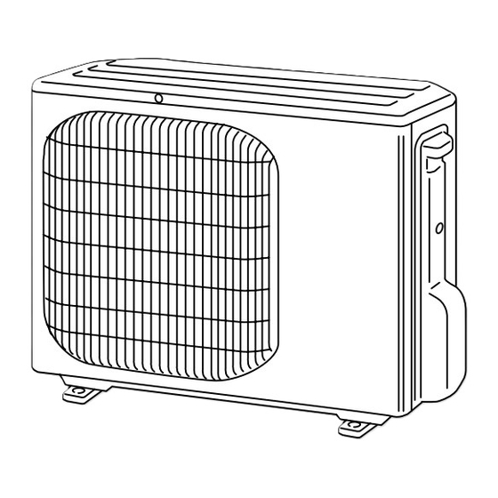
PART NAMES AND FUNCTIONS MUZ-GC25NA MUZ-GC35NA Air inlet Piping Drain hose Air outlet Drain outlet MUZ-GC50NA MUZ-GC60NA MUZ-GC71NA Air inlet (back and side) Piping Drain hose Air outlet Drain outlet... -
Page 4: Specification
SPECIFICATION Outdoor model MUZ-GC25NA MUZ-GC35NA Function Cooling Heating Cooling Heating Power supply Single phase 220 - 230 V, 60 Hz Capacity 2.5 (0.9-3.0) 3.2 (0.9-4.5) 3.2 (1.0-3.7) 3.6 (0.9-4.8) Rated frequency (Min.-Max.) Power outlet Running current (Total) 3.88 4.44 5.26 5.14 Power input (Total) 1,065... - Page 5 Outdoor model MUZ-GC50NA MUZ-GC60NA MUZ-GC71NA Function Cooling Heating Cooling Heating Cooling Heating Power supply Single phase 220 - 230 V, 60 Hz Capacity Rated frequency 5.0 (1.2-5.8) 5.6 (1.2-7.8) 6.0 (1.2-6.7) 6.8 (1.2-8.1) 7.1 (1.4-8.3) 8.1 (1.4-9.6) (Min.-Max.) Power outlet 8.26 10.33 Running current 1 (Total)
- Page 6 Specifi cations and rating conditions of main electric parts Model MUZ-GC25NA MUZ-GC35NA Item Current transformer (CT) 20 A Smoothing capacitor (C61, C62) 500 μF 420 V Diode module (DB61) 15 A 600 V (DB65) 10 A 600 V Fuse (F61) 250 V 20 A (F701, F801) 250 V 3.15 A...
- Page 7 Model MUZ-GC50NA- Item (CT) 20 A Current transformer (CT761, CT781) 15 A Smoothing capacitor (C61, C62, C63) 620 μF 420 V (DB61) 25 A 600 V Diode module (DB65) 25 A 600 V (F61) T20AL250V Fuse (F701, F801, F901) T3.15AL250V Intelligent power module (IPM) 20 A 600 V...
-
Page 8: Outlines And Dimensions
OUTLINES AND DIMENSIONS MUZ-GC25NA MUZ-GC35NA Unit : mm REQUIRED SPACE Basically open 100 mm or more without any obstruction in front and on both sides of the unit. 381.5 Air in Air in Open two sides of left, right, or rear side. Air out 2 holes 10×16 Service panel... -
Page 9: Wiring Diagram
WIRING DIAGRAM MUZ-GC25NA MUZ-GC35NA... - Page 10 MUZ-GC50NA MUZ-GC60NA...
- Page 11 MUZ-GC50NA...
- Page 12 MUZ-GC60NA...
- Page 13 MUZ-GC71NA...
-
Page 14: Refrigerant System Diagram
REFRIGERANT SYSTEM DIAGRAM MUZ-GC25NA MUZ-GC35NA Unit : mm 4-way valve Refrigerant pipe ø9.52 (with heat insulator) Muffler Stop valve (with service port) Outdoor Muffler Discharge heat Flared connection exchanger temperature thermistor RT62 Compressor Defrost thermistor RT61 Strainer #100 Flared connection Capillary tube R.V. - Page 15 MUZ-GC50NA - Unit : mm Muffler #100 4-way valve Refrigerant pipe ø12.7 (with heat insulator) Stop valve (with service port) Outdoor Flared connection Discharge heat Ambient temperature exchanger temperature thermistor Defrost thermistor RT62 thermistor RT65 RT61 Compressor Outdoor heat exchanger temperature thermistor RT68...
- Page 16 MUZ-GC60NA Unit : mm Muffler #100 4-way valve Refrigerant pipe ø15.88 (with heat insulator) Stop valve (with service port) Outdoor High-pressure Flared connection Discharge heat switch Ambient temperature exchanger temperature thermistor thermistor Defrost RT62 thermistor RT65 RT61 Compressor Outdoor heat exchanger temperature thermistor...
- Page 17 MAX. REFRIGERANT PIPING LENGTH and MAX. HEIGHT DIFFERENCE Refrigerant piping : m Piping size O.D : mm Model Max. Length Max. Height difference Liquid MUZ-GC25NA 9.52 MUZ-GC35NA 6.35 MUZ-GC50NA 12.7 MUZ-GC60NA 15.88 MUZ-GC71NA 9.52 Indoor unit Max. Height difference Max. Length Outdoor unit ADDITIONAL REFRIGERANT CHARGE (R410A : g) Refrigerant piping length (one way)
-
Page 18: Performance Curves
PERFORMANCE CURVES MUZ-GC25NA MUZ-GC35NA MUZ-GC50NA MUZ-GC60NA MUZ-GC71NA The standard specifications apply only to the operation of the air conditioner under normal conditions. Since operating condi- tions vary according to the areas where these units are installed, the following information has been provided to clarify the operating characteristics of the air conditioner under the conditions indicated by the performance curve. -
Page 19: Defrost Operation
Total inpup (Heating : at Rated frequency) Heating capacity (at Rated frequency) 20.9 22.4 24.1 23.4 27.9 19.3 20.7 22.3 21.6 25.7 17.7 19.0 20.4 19.8 23.6 16.1 17.2 18.5 18.0 21.4 14.5 15.5 16.7 16.2 19.3 12.9 13.8 14.8 14.4 17.2 11.3... - Page 20 MUZ-GC60NA Correction of Cooling capacity Correction of Cooling total input Correction of Heating total input Correction of Heating capacity (Hz) (Hz) (Hz) (Hz) The operational frequency of compressor The operational frequency of compressor The operational frequency of compressor The operational frequency of compressor MUZ-GC71NA Correction of Cooling capacity Correction of Cooling total input...
-
Page 21: Cool Operation
6-4. OUTDOOR LOW PRESSURE AND OUTDOOR UNIT CURRENT COOL operation Dry-bulb temperature (°C) Relative humidity(%) Both indoor and outdoor unit are under the same tempera- ture/humidity condition. Operation : TEST RUN OPERATION (refer to 6-3.) Outdoor low pressure MUZ-GC50NA MUZ-GC25NA MUZ-GC35NA MUZ-GC60NA 35(°C) -
Page 22: Heat Operation
HEAT operation Indoor Outdoor Condition : Dry bulb temperature (°C) 20.0 20.0 Wet bulb temperature (°C) 14.5 14.5 Operation : TEST RUN OPERATION (refer to 6-3.) Outdoor unit current MUZ-GC25NA MUZ-GC35NA 25(°C) 25(°C) Ambient temperature(°C) Ambient temperature(°C) MUZ-GC60NA MUZ-GC50NA 5 7 10 25(°C) 25(°C) Ambient temperature(°C) -
Page 23: Actuator Control
ACTUATOR CONTROL MUZ-GC25NA MUZ-GC35NA MUZ-GC50NA MUZ-GC60NA MUZ-GC71NA 7-1. OUTDOOR FAN MOTOR CONTROL The fan motor turns ON/OFF, interlocking with the compressor. [ON] The fan motor turns ON 5 seconds before the compressor starts up. [OFF] The fan motor turns OFF 15 seconds after the compressor has stopped running. 5 seconds 15 seconds Compressor... -
Page 24: Service Functions
SERVICE FUNCTIONS 8-1. CHANGE IN DEFROST SETTING [MUZ-GC25/35 MUZ-GC50NA- Changing defrosting finish temperature <JS> When the JS wire of the outdoor Inverter P.C. board is cut/soldered, the defrost finish temperature is changed. (Refer to 9-6.1.) Defrost fi nish temperature (°C) Jumper wire MUZ-GC25/35 MUZ-GC50NA-... -
Page 25: Failure Mode Recall Function
9-2. FAILURE MODE RECALL FUNCTION Outline of the function This air conditioner can memorize the abnormal condition which has occurred once. Even though LED indication listed on the troubleshooting check table (9-3.) disappears, the memorized failure details can be recalled. This mode is very useful when the unit needs to be repaired for the abnormality which doesn't recur. - Page 26 2. Flow chart of the detailed outdoor unit failure mode recall function Operational procedure The outdoor unit might be abnormal. Confi rm if outdoor unit is abnormal according to the following procedures. Confi rm that the remote controller is in the failure mode recall function. 1.
- Page 27 3. Outdoor unit failure mode table MUZ-GC25/35NA The upper lamp Indoor/outdoor LED indication Outdoor unit of OPERATION Abnormal point unit failure (Outdoor P.C. Condition Correspondence failure mode INDICATOR lamp (Failure mode / protection) mode recall board) recall function (Indoor unit) function —...
- Page 28 MUZ-GC50NA- MUZ-GC60/71NA The left lamp of Indoor/outdoor LED indication OPERATION Abnormal point unit failure (Outdoor P.C. board) Condition Correspondence INDICATOR lamp (Failure mode / protection) mode recall LED 1 LED 2 (Indoor unit) function None (Normal) — — — — —...
- Page 29 MUZ-GC50NA- Indoor/outdoor The left lamp of Outdoor unit Abnormal point LED indication unit failure OPERATION INDICATOR Condition Correspondence failure mode (Failure mode / protection) (Outdoor P.C. board) mode recall lamp (Indoor unit) recall function function None (Normal) — — — —...
-
Page 30: Troubleshooting Check Table
9-3. TROUBLESHOOTING CHECK TABLE MUZ-GC25/35NA Abnormal point/ Symptom LED indication Condition Correspondence Condition Outdoor unit 1-time fl ash every Outdoor power system Overcurrent protection stop is continuously performed 3 times • Reconnect connector of does not 2.5 seconds within 1 minute after the compressor gets started. compressor. - Page 31 MUZ-GC50NA- MUZ-GC60/71NA Indication Abnormal point / Symptom Condition Correspondence LED1 LED2 Condition (Red) (Yellow) Outdoor unit Lightning Twice Overcurrent protection stop is continuously performed 3 times • Check the connection of the com- does not op- within 1 minute after the compressor gets started, or when pressor connecting wire.
- Page 32 Indication Abnormal point / Symptom Condition Correspondence LED2 Condition LED1 (Red) (Yellow) Outdoor unit Once Lighting These symptoms do not mean any ab- Primary current protection The input current exceeds 15 A. operates. normality of the product, but check the Secondary current protec- The current of the compressor exceeds 15 A.
- Page 33 MUZ-GC50NA- Abnormal point/ Symptom LED indication Condition Correspondence Condition Outdoor unit 1-time fl ash every Outdoor power sys- Overcurrent protection stop is continuously performed 3 times • Reconnect connector of compres- does not oper- 2.5 seconds within 1 minute after the compressor gets started, or failure of sor.
- Page 34 9-4. TROUBLE CRITERION OF MAIN PARTS MUZ-GC25NA MUZ-GC35NA Part name Check method and criterion Figure Defrost thermistor (RT61) Measure the resistance with a tester. Refer to 9-6. “Test point diagram and voltage”, 1. “Inverter P.C. board”, the chart of thermistor. Discharge temperature Measure the resistance with a tester.
- Page 35 MUZ-GC50NA MUZ-GC60NA MUZ-GC71NA Part name Check method and criterion Figure Defrost thermistor (RT61) Measure the resistance with a tester. Ambient temperature ther- mistor (RT65) Refer to 9-6. "Test point diagram and voltage", 1. "Inverter P.C. board" or 2. "Outdoor electronic control P.C. board”, the chart of Outdoor heat exchanger tem- thermistor.
-
Page 36: A How To Check Inverter/Compressor
9-5. TROUBLESHOOTING FLOW A How to check inverter/compressor MUZ-GC25/35NA MUZ-GC50NA- Disconnect the connector (CN61) between compressor and the intel- ligent power module (IPM). Check the voltage See 9-5. “Check of open phase” . between terminals. Are the voltages Replace the inverter P.C. board. balanced? Check the compres- See 9-5. - Page 37 B Check of open phase MUZ-GC25/35NA MUZ-GC50NA- ● With the connector between the compressor and the intelligent power module disconnected, activate the inverter and check if the inverter is normal by measuring the balance of voltage between the terminals. Output voltage is 50 - 130 V. (The voltage may differ according to the tester.) <<...
- Page 38 E Check of compressor operation time MUZ-GC25/35NA MUZ-GC50NA- <<Judgement>> ● Connect the compressor and activate the inverter. Then measure the time until the inverter stops due to over current. 0 second Compressor starts <<Operation method>> Start heating or cooling operation by pressing EMERGENCY 1 second Abnormal OPERATION switch on the indoor unit.
- Page 39 G Check of outdoor thermistors Disconnect the connector of thermistor in the outdoor P.C. board (see below table), and measure the resistance of thermistor. Replace the thermistor except RT64. Is the thermistor normal? (Refer to 9-6.1. When RT64 is abnormal, replace the inverter P.C. or 9-6.2.) board or the outdoor power board.
- Page 40 MUZ-GC50NA- MUZ-GC60/71NA • Heating operation does not work. Disconnect the lead wire leading to the compressor. 3 minutes after turning on the power supply, start EMERGENCY OPERATION in HEAT mode. Is there voltage of 220 - 230 VAC between pin1 Turn off power supply of indoor and outdoor unit, and discon- and pin 2 at connector CN912? nect the connector CN781 in the outdoor electronic control P.C.
- Page 41 I Check of outdoor fan motor MUZ-GC25/35NA Check the resistance of fan motor. (Refer to 9-4.) Is the resistance of Replace the outdoor fan motor normal? fan motor. Disconnect the connector CN771 on the power P.C. board. Disconnect the connector (CN61) between compressor and power transistor module.
- Page 42 J Check of power supply MUZ-GC25/35NA MUZ-GC50NA- Disconnect the connector (CN61) between compressor and intelligent power module. Rectify indoor/outdoor Turn ON power supply and press connecting wire. EMERGENCY OPERATION switch. Is there voltage 220 - 230 VAC Replace the indoor Does the upper or left lamp of between the indoor terminal electronic control P.C.
- Page 43 K Check of LEV (Expansion valve) MUZ-GC25/35NA MUZ-GC50NA- Turn ON the power supply. <Preparation of the remote controller> While pressing both OPERATION SELECT button and TOO COOL button on the remote controller at the same time, press RESET button. First, release RESET button. And release the other two buttons after all LCD except the set temperature in operation display section of the remote controller is displayed after 3 seconds.
- Page 44 L Check of inverter P.C. board MUZ-GC50NA- Check the outdoor fan motor. (Refer to 9-5. .) Is the fuse (F901) blown on the in- verter P.C. board? Check the connection of the connectors (CN931, CN932) of the outdoor fan mo- tor.
- Page 45 M How to check miswiring and serial signal error MUZ-GC25/35NA Turn OFF the power supply. Is there rated voltage in the Check the power supply. power supply? Turn ON the power supply. Is there rated voltage between outdoor terminal block S1 and Check the wiring.
- Page 46 MUZ-GC50/60/71NA Turn OFF the power supply. Is there rated voltage in the Check the power supply. power supply? Turn ON the power supply. Is there rated voltage between outdoor termi- Check the wiring. nal block S1 and S2? Press EMERGENCY OPERATION switch once. Does the left lamp of OPERATION INDICA- TOR lamp light up? <Confi...
- Page 47 N Check of HPS MUZ-GC60NA MUZ-GC71NA 1. Disconnect the connector CN681 in the outdoor electronic control P.C. board. 2. Check the resistance of HPS 1 minute after the outdoor unit power supply was turned OFF. Check the resistance between each terminal. Replace HPS.
- Page 48 O Electromagnetic noise enters into TV sets or radios Is the unit earthed? Earth the unit. Is the distance between the antennas Extend the distance between the antennas and and the indoor unit within 3 m, or is the the indoor unit, and/or the antennas and the distance between the antennas and the outdoor unit.
- Page 49 9-6. TEST POINT DIAGRAM AND VOLTAGE 1. Inverter P.C. board MUZ-GC25NA MUZ-GC35NA Fuse Smoothing capacitor Smoothing capacitor Varistor Varistor (F801) (C61) (C62) (NR62) (NR61) DB61 Varistor Back side of unit 220-230V AC (NR63) DB61 280V ~ 370V Fuse Output to (F701) drive compressor...
- Page 50 MUZ-GC50NA- Smoothing Smoothing Smoothing capacitor capacitor capacitor Fuse (F701) DB61 Back side of unit (C62) (C63) (C61) 250 V 3.15 A DC 260 - 300 V Fuse (F801) AC 220 - 230 V 250 V 3.15 A R.V.coil (CN721) 220 - 230 Fuse (F901) 250 V 3.15 A Output to...
- Page 51 2. Outdoor electronic control P.C. board Defrost thermistor (RT61) Ambient temperature thermistor (RT65) MUZ-GC50NA- MUZ-GC71NA Outdoor heat exchanger MUZ-GC60NA Fin temperature thermistor (RT64) temperature thermistor (RT68) Discharge temperature thermistor (RT62) 10 20 30 40 50 60 70 80 100 110 120 Temperature (°C) Temperature (°C) Temperature (°C)
- Page 52 3. Noise filter P.C. board MUZ-GC50NA- MUZ-GC60NA MUZ-GC71NA CN901 To electronic CN902 CN903 control To power To power P.C. board board board 220-230V AC Input CN912 R.V. coil 220-230V AC CN61 220-230V AC 220-230V AC Output Output NR64 VARISTOR F64 FUSE F911 FUSE 2A/250V 1A/250V...
- Page 53 4. Outdoor power board MUZ-GC50NA- MUZ-GC60NA MUZ-GC71NA Connect to the compressor Voltage among phases: 5V to 180V Connect to the earth 310-370V DC Output (Red) Connect to the controller board (+)1-5(–): Signal transmission (To electronic control P.C. board) 5V DC pulse wave (–) (+)2-5(–): Zero cross signal (White)
-
Page 54: Disassembly Instructions
DISASSEMBLY INSTRUCTIONS <"Terminal with locking mechanism" Detaching points> The terminal which has the locking mechanism can be detached as shown below. There are two types ( Refer to (1) and (2)) of the terminal with locking mechanism. The terminal without locking mechanism can be detached by pulling it out. Check the shape of the terminal before detaching. - Page 55 OPERATING PROCEDURE PHOTOS 2. Removing the inverter assembly, inverter P.C. board Photo 3 Screws of the (1) Remove the cabinet and panels. (Refer to 1.) relay panel (2) Disconnect the earth wires (Photo 3.), the lead wire to the reactor and the following connectors; Screws of <Inverter P.C.
- Page 56 OPERATING PROCEDURE PHOTOS 5. Removing outdoor fan motor Photo 6 (1) Remove the cabinet and panels. (Refer to 1.) (2) Disconnect the connectors for outdoor fan motor. (3) Remove the propeller nut. (Photo 7.) (4) Remove the propeller. (Photo 7.) (5) Remove the screws fixing the fan motor.
- Page 57 10-2. MUZ-GC50NA MUZ-GC60NA MUZ-GC71NA NOTE : These photos are MUZ-GC71NA. Other models are almost the same as MUZ-GC71NA. Turn OFF power supply. before disassembling. OPERATING PROCEDURE PHOTOS 1. Removing the cabinet Photo 1 (1) Remove the screws of the service panel. (2) Remove the screws of the top panel.
- Page 58 OPERATING PROCEDURE PHOTOS MUZ-GC50NA- MUZ-GC60/71 Photo 4 ( MUZ-GC50NA- MUZ-GC60/71 2. Removing the inverter assembly, inverter P.C. board Screws of the power board assembly and power board (1) Remove the top panel, cabinet and service panel. (Refer to (2) Remove the back panel. (Refer to 1.) (3) Disconnect the following connectors;...
- Page 59 OPERATING PROCEDURE PHOTOS 4. Removing R.V. coil Photo 7 (1) Remove the top panel, cabinet and service panel. (Refer to Discharge temperature thermistor (2) Remove the back panel. (Refer to 1.) (3) Disconnect the following connectors; MUZ-GC50NA- MUZ-GC60/71 <Noise filter P.C. board> CN912 (R.V.
- Page 60 OPERATING PROCEDURE PHOTOS 7. Removing the compressor and 4-way valve Photo 10 (1) Remove the top panel, cabinet and service panel. (Refer to (2) Remove the back panel. (Refer to 1.) (3) Remove the inverter assembly. (Refer to 2.) (4) Recover gas from the refrigerant circuit. NOTE: Recover gas from the pipes until the pressure gauge shows 0 kg/cm...
- Page 64 HEAD OFFICE: TOKYO BLDG., 2-7-3, MARUNOUCHI, CHIYODA-KU, TOKYO 100-8310, JAPAN Copyright 2007 MITSUBISHI ELECTRIC ENGINEERING CO.,LTD Distributed in Aug. 2008. No. OBH482 REVISED EDITION-C 6 Distributed in Jun. 2008. No. OBH482 REVISED EDITION-B 6 Distributed in Nov. 2007. No. OBH482 REVISED EDITION-A 6 Distributed in Mar.
Need help?
Do you have a question about the Mr.Slim MUZ-GC25NA - C1 and is the answer not in the manual?
Questions and answers