Citizen iDP-460 User Manual
Hide thumbs
Also See for iDP-460:
- User manual (79 pages) ,
- User manual (4 pages) ,
- Product manual (24 pages)
Table of Contents
Advertisement
Quick Links
Download this manual
See also:
User Manual
Advertisement
Table of Contents

Related Manuals for Citizen iDP-460


Summary of Contents for Citizen iDP-460
- Page 1 CITIZEN User's Manual Model : iDP-460 Dot Matrix Printer Rev.1.00 Newly issued on Feb. 26. 1998 Japan CBM Corporation Information Systems Div.
-
Page 2: Declaration Of Conformity
User’s Manual Declaration of Conformity Manufacturer’s Name : : Japan CBM Corporation Manufacturer’s Address : 1-1-7, Okubo, Shinjuku-ku, Tokyo 169-8553, Japan Declare the Product Product Name Dot Matrix Printer Model Number(s) iDP460 (iDP460P, iDP460R, iDP460V) (S.NO.9830001 - ) Conform to the following Standards... -
Page 3: Important Safety Instructions
User’s Manual IMPORTANT SAFETY INSTRUCTIONS •Read all of these instructions and save them for future reference. •Follow all warnings and instructions marked on the product. •Unplug this product from the wall outlet before cleaning. Do not use liquid or aerosol cleaners. Use a damp cloth for cleaning. - Page 4 User’s Manual grundsätzlich Stecker aus der Steckdose ziehen. Keine Flüssigkeiten oder Aerosolreiniger benutzen. Nut mit einem feuchten Tuch abwischen. •Der Drucker darf nicht in der Nähe von Wasser aufgestellt werden. •Drucker nicht auf einem unstabilen Wagen, Stand oder Tisch aufstellen.
- Page 5 User’s Manual IMPORTANT: This equipment generates, uses, and can radiate radio frequency energy and if not installed and used in accordance with the instruction manual, may cause interference to radio communications. It has been tested and found to comply with the limits for a Class A computing device pursuant to Subpart J of Part 15 off FCC Rules, which are designed to provide reasonable protection against such interference when operated in a commercial environment.
- Page 6 User’s Manual CAUTION This equipment is a Class-A information technology system based on the standards of the Radio Interference Voluntary Regulations Council for Information Processing Systems (VCCI). Use of this system in a domestic environment may cause radio interference. If this occurs, the user may be...
- Page 7 User’s Manual SAFETY PRECAUTIONS ----- BE SURE TO OBSERVE In order to prevent hazards to an operator or other persons and damage to property, be sure to observe the following precautions. l The following describes the degrees of hazard and damages that can occur if the given instructions are neglected or the equipment is incorrectly operated.
- Page 8 User’s Manual WARNING l Never handle the equipment in the following manners, as it may break, become out of order, or overheat causing smoke and resulting in fire or electric shock. If the equipment is used in an abnormal condition, such as when broken, then problems, smoke emission, abnormal odor/noise, and fire can result.
-
Page 9: Precautions For Installation
User’s Manual PRECAUTIONS FOR INSTALLATION • Do not use or store the equipment in a place exposed to fire, moisture, or direct sunlight, or in a place near a heater or a thermal device where the prescribed operating temperature and humidity are not met, or in a place exposed to much oil, iron powder, or dust. -
Page 10: Precautions For Handling
User’s Manual PRECAUTIONS FOR HANDLING Do not handle the equipment in the following manners, because problems may result. • Do not use a power supply other than the specified AC adapter. • Do not print when there is no recording paper or ink ribbon set in the equipment. The print head may be damaged •... -
Page 11: Daily Maintenance
User’s Manual DAILY MAINTENANCE • Prior to starting maintenance work, be sure to turn off the main body. • Use a dry soft cloth to wipe off stains and dust from the surfaces of the main body case. For severe soiling, dip the cloth in water and wring it, for wiping off the soil. -
Page 12: Table Of Contents
User’s Manual CONTENTS OUTLINE ............................. 15 1.1 Features................................15 1.2 Unpacking..............................15 BASIC SPECIFICATIONS........................16 2.1 Model Classifications ............................16 2.2 Basic Specifications............................17 2.3 Paper Specifications............................18 2.3.1 Recommended Paper........................18 2.3.2 Printing Position..........................18 2.3.3 Cutter Layout ...........................18 OUTER APPEARANCE AND COMPONENT PARTS ................ 19 OPERATION............................ - Page 13 User’s Manual 8.1.2 Drive Circuit.............................40 8.2 Specifications of Power Supply Connector .....................41 MAINTENANCE AND SERVICE ....................... 42 10. PRINT CONTROL FUNCTIONS ......................43 10.1 Command List..............................43 10.2 Command Sets ...............................44 10.3 Command Details ............................45 10.3.1 Description of Items.........................46 10.3.2...
-
Page 14: Outline
User’s Manual 1. OUTLINE This is a small-size dot impact printer developed for various data communication terminals, POS terminals, kitchen-use printers, bank card, terminals, and so on. Its abundant built-in features allow you to widely use this printer for different applications. Prior to using it, read and understand this manual thoroughly. - Page 15 User’s Manual h Exclusive AC Adapter Types and Power Cords • 34AD-U (120 V 2-core cord) • 34AD-E (230 V 2-core cord)
-
Page 16: Basic Specifications
User’s Manual 2.2 Basic Specifications Model iDP 460-RF120 iDP 460-RF230 iDP 460-VF120 iDP 460-VF230 Item iDP 460-PF120 iDP 460-PF230 Print method Serial dot impact method (Bidirectional print) Print width 64mm Print head 7-pin Print speed Approx. 3 lines/sec. (At single color continuous print) -
Page 17: Paper Specifications
User’s Manual 2.3 Paper Specification 2.3.1 Recommended Paper •Type : Normal paper and non-carbon paper •Paper width : 76 +/- 0.5 mm •Paper thickness : Single-sheet paper --- 45 to 55 kg/1,000 sheets/1,091 x 788 mm; Copying paper - Non-carbon paper, 1 original + 1 copy, Total thickness 0.2 mm or less... -
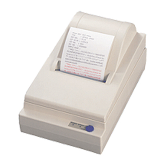
Page 18: Outer Appearance And Component Parts
User’s Manual 3. OUTER APPEARANCE AND COMPONENT PARTS 4. OPERATION 4.1 Connecting AC Adapter... - Page 19 User’s Manual (1)Turn off the Power switch. (2) Connect the cable connector of the AC adapter to the power connector located on the back of the printer. (3) In order to prevent disconnection of the cable connector, put it through a wire saddle, as shown in the figure below.
-
Page 20: Connecting Interface Cable
User’s Manual 4.2 Connecting Interface Cable (1) Turn off the power. (Mating side included) (2) Check the top and bottom of the cable terminals, and connect to the interface connector. (3) Fix the cable terminals. •Serial interface: Tighten screws, to fix. -
Page 21: Setting The Cassette Ribbon
User’s Manual 4.4 Setting the Cassette Ribbon (1) Open the printer cover. (2) If the ribbon is slackened, turn the knob in the arrow-indicated direction to give the tension to it before setting. (3) While putting the ribbon in between the head cover and platen, push the locking claws into the holder of the printer. -
Page 22: Inserting The Paper
User’s Manual 4.5 Inserting the Paper (1) Put your hands in the concave parts on both sides of the printer cover, and open it until it comes to a stop. (2) Cut the end of the paper roll at close to a right angle. - Page 23 User’s Manual : • If the paper is slack, rewind it, to remove the slack. CAUTION • If the paper is set slantwise, operate the paper-free lever, to correct the paper position. • While printing, do not hold the paper. This can cause a paper jam.
-
Page 24: How To Remove Remaining Paper Roll
User’s Manual 4.6 How to Remove Remaining Paper Roll (1) Open the printer cover. (2) Pushing the paper-free lever in the arrow direction, pull out the paper roll. CAUTION : When pulling out the paper (forward/reverse direction), be sure to operate the paper-free lever. -
Page 25: Operation Panel And Display Of Error
User’s Manual 4.8 Operation Panel and Display of Error (1) POWER lamp(green) Illuminated when the power is turned on. (2) ERROR lamp(red) Illuminated when the printer is out of paper or has a printer mechanical error or communication error (serial). -
Page 26: Print Duty
User’s Manual 4.9 Print Duty As the printing head mounted onto this printer is not equipped with a head temperature detection sensor (thermistor), the printer protects the printing head against temperature through software. The printer calculates the number of print dots and prints as follows, depending on whether the number of printing dots per line is over or within 500. - Page 27 User’s Manual (2) Remove a cassette ribbon. The DIP switches are located as shown in the figure below. (Only DS1 provided for the parallel interface)
-
Page 28: Parallel Interface
User’s Manual <DIP Switches Setting> 1) DS1 Function Setting upon Shipment Font Japan International Auto loading Disable Enable Not available (*1) Paper used 2) DS2 Function Setting upon Shipment Bit length 7 bits 8 bits Parity Parity Even At error Prints "?"... - Page 29 User’s Manual Cable side --- 57-30360 (Ditto) 6.2 Connector’s Pin Confuguration Signal Name Signal Name TWISTED PAIR GND ↑ DATA 1 ↑ DATA 2 ↑ DATA 3 ↑ DATA 4 ↑ DATA 5 ↑ DATA 6 ↑ DATA 7 ↑...
-
Page 30: Input And Output Signals
User’s Manual 6.3 Input and Output Signals 6.3.1 Input and Output Signals (1) Input signals to the printer • DATA : An 8-bit parallel signal. (Positive logic) • STB : A strobe signal to read the 8-bit data. (Negative logic) (2) Output signals from the printer •... -
Page 31: Electrical Characteristics
User’s Manual 6.3.2 Electrical Characteristics (1) Input signal level All the input signals are at the TTL level. "HIGH" level : 2.0 V at minimum "LOW" level : 0.8 V at maximum (2) Output signal level All the output signals are at the TTL level. -
Page 32: Timing Chart
User’s Manual 6.3.3 Timing Chart (1) Data input and printing timing T1, T2, T3 : 0.5 µs MIN : 270 ns MAX : 2.3 µs TYP : 500 ms MIN (At power-on) 6.3.4 Data Receiving Control When the BUSY signal is at "LOW," the printer can receive the data from the host, but when at "HIGH," it cannot. - Page 33 User’s Manual (4) Signal polarity RS-232C •Mark = Logic "1" (-3 V to -12 V) •Space = Logic "0" (+3 V to +12 V) (5) Received data (RD signal) RS-232C • Mark • Space (6) Reception control (DTR signal) RS-232C •Mark...
-
Page 34: Connector's Pin Configuration
User’s Manual 7.2 Connector’s Pin Configuration D-Sub Mini Connector Connector Signal Function Shell Frame Ground Signal GND Input Received Data Output Printer BUSY signal Output Transmitted Data Input Data Set Ready D-Sub Connector Mini DIN Connector Cautions: 1. An RS-232C signal is based on the EIA RS-232C. -
Page 35: Input And Output Signals
User’s Manual 7.3 Input and Output Signals 7.3.1 Input and Output Signals (1) RD This is a serial received data signal. When a framing error, overrun error, or parity error occurs, that data is printed as "?" or discarded. (Depends on DIP switch selection.) The ERROR lamp is illuminated. -
Page 36: Data Configuration
User’s Manual 7.3.2 Data Configuration Mark ,..Space (1) Start Bit (2) Data Bit (+ Parity Bit) (3) Stop Bit (1 or More) (1) Start bit After a lapse of 1/2 bit from a mark-to-space fall edge, the state is read again, and if it is a space, it is recognized as the start bit. -
Page 37: Error Detection
User’s Manual 7.3.3 Error Detection A parity error, framing error, and overrun error are detected. When an error is detected, that data is either stored in the buffer as "?" or discarded. (Depends on DIP switch selection) The ERROR lamp is illuminated. -
Page 38: Electrical Characteristics
User’s Manual 7.3.6 Electrical Characteristics (1) RS-232C circuit Input (RD, DSR) [Printer Side] [Host Side] Mark=(-8V): Stop bit Space=(+8V): Start bit Equivalent MAX232 Output (DTR, TD) Equivalent to MAX232 Mark=(-8V): At Busy Mark=(-8V): 1 Space=(+8V): At Ready Space=(+8V): 0 8. -
Page 39: Drive Circuit
User’s Manual Common ground on the circuit Connector used : TM5RJ3-66(HIROSE) or equivalent Applicable connector : TM3P-66P(HIROSE) or equivalent CAUTION :•No output is made while printing. A solenoid used for the drawer should be of 36 Ω or more. An output current should be kept below 0.8 A. -
Page 40: Specifications Of Power Supply Connector
User’s Manual 8.2 Specifications of Power Supply Connector This is a power connector from an exclusive AC adapter. Connector’s Pin Configuration Function +24V Jack used : HEC0470-01-640(HOSHIDEN) or equivalent Applicable plug : JXP series Type-A (I.D. 2.45 mm, O.D. 5.5 mm) (HOSHIDEN) or equivalent •... -
Page 41: Print Control Functions
User’s Manual PRINT CONTROL FUNCTIONS 10.1Command List Command Function Code P200 P250 Refer to Line Feed Eject Paper Clear Print Buffer and Cancel Character Attribute NULL Pad character (NOP) Specify Red print × Execute P-250 Mode × Execute P-200 Mode... - Page 42 User’s Manual P-250 mode basically equals to P-900R except the printer ID and some status sent to the host from the printer. Refer to the attached “Detail of Commands”. * P200 represents the P-200 mode. * O: Command enable, ×: Command disable * (n) in the command indicates the character code 30ch to 39ch.
-
Page 43: Command Sets
User’s Manual 10.2Command Sets A command set is set by a specific command. The available commands and functions differ depending on each setting. (1) P-250 command set There are two kinds of modes; P-200 mode and P-250 mode. The P-900R mode are available with a P-900R mode and P-250 mode command. -
Page 44: Command Details
User’s Manual 10.3Command Details 10.3.1 Description of Items XXXX [Name] Command name [Code] A sequence of code constituting a command is represented in hexadecimal number for < >H, binary number for < >B, and decimal number for < >, respectively; [ ]k represents a repeat count of k-times. -
Page 45: Details
User’s Manual 10-3-2 Details [Name] Feed Paper [Code] <0A>H [Function] This command prints the data in the print buffer and feeds the paper by one line. If printing is completed, the command will shifts a printing position to the left margin and clear the print buffer. - Page 46 User’s Manual [Name] Clear Print Buffer and Cancel Character Attribute [Code] <18>H [Function] This command clears the contents of the print buffer without printing them and resets the character attribute and other attributes to Inactive or Default. [Caution] If the printer has started printing from the print buffer, this command will be ignored.
- Page 47 User’s Manual P-200,40ch [Name] Execute P-250 Mode [Code] <1C>H [Function] This command resets all the attributes, clears the print buffer, and set the right margin to 42. A subsequent command and printer operation will be of the P-250 mode.
- Page 48 User’s Manual [Name] Set Double Width Character [Code] <1E>H [Function] This command prints its subsequent characters in double width. When there is only one character worth of position in a line, it will be printed in normal width. This attribute remains valid until the US command(normal width mode) or CAN command is received.
- Page 49 User’s Manual [Function] 1. Serial interface 7-bit setting High pages are specified in all the modes. If this command is received, the character codes 20H to 7FH will be converted into A0H to FFH. This command remains valid until the SI command or CAN command is received.
- Page 50 User’s Manual BELL (D-type Only) [Name] Drawer kickout [Code] <07>H [Function] This command outputs a designation signal to the connected drawer interface. The signal is about 200 ms. Designation is made when the solenoid is connected. The command functions even if not connected to the drawer interface, but it is meaningless.
- Page 51 User’s Manual [Code] <1B>H<62H>(n)<3B>H 1 ≤ (n)≤ 255 (<30>H ≤ n ≤ <39>H) [Domain] [Function] This command ejects the paper by n-lines at the specified line height. [Caution] Be sure to add ";"(<3B>H) to the end of the parameter. If 0 or 256 or more is specified for the parameter, this command will be ignored.
- Page 52 User’s Manual ESC d P-250, P-900R [Name] Request Printer Status [Code] <1B>H<64>H [Function] In the P-250 mode and P-900R mode, this command sends the following 1-byte status messages shown below. This command is valid only for the serial interface.
- Page 53 User’s Manual [Sample Program] When setting the right margin to 10 ESC e 10 ; → LPRINT CHR$(&H1B)+”e10;”; <1B>H<65>H<31>H<30>H<3B>H [See Also] SO, SI, RS, US ESC h (n) ; [Name] Select Character Set [Code] <1B>H<68H>(n)<3B>H 0 ≤(n) ≤10 (<30>H ≤ n ≤<39>H)
-
Page 54: Character Codes Table
User’s Manual [Name] Select P-900R Mode [Code] <1B>H<78>H [Function] Any command or function following this command works as the P-900R mode. [Caution] This command can be canceled by the FS, GS, or ESC c command. [See Also] FS, GS, ESC c 11.CHARACTER CODES TABLE... -
Page 55: Japanese
User’s Manual 11.2 Japanese... -
Page 56: International Character Codes Table
User’s Manual 11.3 International Character Codes Table(All Common) APPENDIX 1. BLOCK DIAGRAM... - Page 57 User’s Manual OSC16MHz Driver POWER LED Print ERROR LED Head FEED Switch Paper DIP Switch Driver Drawer Driver Moter Interface Parallel Driver (CENTRONICS) Serial Printer (RS-232C ) Mechanism Reset Vp Vcc AC Adapter Vp :For mechanism drive, Filter 34 AD Series...
-
Page 58: Appendix 2. Outline Drawing
User’s Manual APPENDIX 2. OUTLINE DRAWING... -
Page 59: German
User’s Manual <<< German >>> <VORSICHT> 1. Bitte lesen Sie die Bedienungsanleitung vor dem Betrieb des Geräts aufmerksam durch und bewahren Sie die Anleitung anschließend für späteres Nachschlagen an einem sicheren Platz auf. 2. Änderungen des Inhalts dieser Anleitung bleiben ohne Vorankündigung vorbehalten. - Page 60 User’s Manual Datenverlust, Unfällen, Reparaturen, Tests usw. keinerlei Haftung übernehmen. 8. Bitte wenden Sie sich mit Fragen oder Hinweisen auf Fehler oder Auslassungen im Text dieser Anleitung an unsere Geschäftsstelle. 9. Beachten Sie jedoch, daß wir, ungeachtet des obigen Punkts 8, keinerlei Haftung für negative Folgeerscheinungen im Zusammenhang mit dem Betrieb dieses Geräts übernehmen.
- Page 61 User’s Manual ZU BEACHTENDE SICHERHEITSMASSREGELN Zur Vermeidung von Gefahren gegenüber dem Bediener und anderen Personen und Sachschäden sind die folgenden Vorsichtsmaßregeln unbedingt zu beachten. l Der folgende Text beschreibt das Ausmaß der Gefahren und potentiellen Sachschäden, die durch eine Mißachtung der Bedienungshinweise oder durch die unsachgemäße Handhabung des Geräts entstehen...
- Page 62 User’s Manual WARNUNG l Bei m Bet rieb des Geräts sind die nachf olgenden Vorsic htsma ßrege ln unbedingt zu beac hten. Eine Mißachtung di eser Hinwe ise kann zu Schäden, Funktionsstörungen, Rauc hentwicklung und Bra ndgef ahr dur ch Überhit zen und zu elektrisc hen Schlägen führen.
- Page 63 User’s Manual VORSICHTSMASSREGELN FÜR DIE AUFSTELLUNG • Das Gerät nicht an Plätzen abstellen oder betreiben, an denen es Feuer, Feuchtigkeit oder direkter Sonnenbestrahlung ausgesetzt ist. Ebenso sind Plätze in der Nähe von Heizkörpern und sonstigen Wärmenquellen zu vermeiden, an denen Umgebungstemperatur und Luftfeuchtigkeit nicht den vorgeschriebenen Betriebsbedingungen entsprechen, sowie Plätze, an denen das Gerät Öl, Metallspänen oder...
- Page 64 User’s Manual VORSICHTSMASSREGELN FÜR DIE HANDHABUNG Zur Vermeidung von Problemen sind bei der Handhabung des Geräts die folgenden Vorsichtsmaßregeln zu beachten. • Für die Stromversorgung ausschließlich das vorgeschriebene Netzteil verwenden. • Den Druckbetrieb nicht ohne eingelegtes Papier oder ohne Farbband starten, da hierdurch der Druckkopf beschädigt werden kann.
-
Page 65: Betrieb
User’s Manual TÄGLICHE WARTUNG • Vor der Wartung zuerst den Drucker ausschalten. • Schmutz und Staub mit einem trockenen, weichen Tuch vom Druckergehäuse abwischen. Bei starker Verschmutzung einen Lappen in Wasser anfeuchten, auswringen und damit abwischen. Hierzu niemals flüchtige organische Lösungsmittel, wie z.B. Alkohol, Terpentin, Trichlorethan, Benzol, Keton oder chemische Staubentfernungsmittel, verwenden. - Page 66 User’s Manual am Kabel ziehen. • Durch Ziehen am Netzadapter-Anschlußkabel können Schäden entstehen, die zu Bränden, elektrischen Schlägen oder gebrochenen Kabeldrähte führen. • Bei einem Gewitter sollte das Netzteil von der Steckdose getrennt und der Drucker nicht verwendet werden. Ein Blitzschlag kann Brände und elektrische Schläge auslösen.
-
Page 67: Anschluß Des Schnittstellenkabels
User’s Manual 4.2 Anschluß des Schnittstellenkabels 1. Den Drucker (einschließlich angeschlossene Geräte) ausschalten. 2. Den Kabelstecker korrekt ausgerichtet (Ober- und Unterseite prüfen) an die Schnittstellenbuchse anschließen. 3. Die Kabelstecker befestigen: •Seriellschnittstelle: durch Festziehen der Schrauben sichern. •Parallelschnittstelle: durch Drehen des Anschlags sichern. -
Page 68: Einsetzen Der Farbbandkassette
User’s Manual 4.4 Einsetzen der Farbbandkassette 1. Die Druckerabdeckung aufklappen. 2. Bei schlaffem Farbband den Knopf in Pfeilrichtung drehen, um das Band vor dem Einsetzen der Kassette straff zu wickeln. 3. Die Farbbandkassette zwischen Druckkopfabdeckung und Walze einsetzen und gleichzeitig die Halteklauen in den Halter des Druckers drücken. -
Page 69: Einlegen Der Papierrolle
User’s Manual 4.5 Einlegen der Papierrolle 1. Mit den Fingern in die Aussparungen an beiden Seiten der Druckerabdeckung greifen, und die Abdeckung durch Anheben bis zum Anschlag öffnen. 2. Das Ende des Druckpapiers in nahezu rechtem Winkel abschneiden. : • Ausschließlich das vorgeschriebene Druckpapier verwenden. - Page 70 User’s Manual : • Schlaffes Druckpapier durch Zurückdrehen der Papierrolle straffen. VORSICHT • Bei schräg eingesetztem Druckpapier den Papier-Freigabehebels drücken und das Papier gerade richten. • Die Druckerabdeckung niemals während des Druckens öffnen, da hierdurch Papierstaus entstehen können.
-
Page 71: Entfernen Des Restlichen Druckpapiers
User’s Manual 4.6 Entfernen des restlichen Druckpapiers 1. Die Druckerabdeckung aufklappen. 2. Den Papier-Freigabehebel in Pfeilrichtung drücken und das Rollenpapier herausziehen. VORSICHT : Beim Herausziehen des Druckpapiers (in Vorwärts- oder Rückwärtsrichtung) darauf achten, den Papier-Freigabehebel zu betätigen. 4.7 Beseitigung von Papierstaus 1. -
Page 72: Bedienfeld Und Fehleranzeigelämpchen
User’s Manual 4.8 Bedienfeld und Fehleranzeigelämpchen 1. Netzanzeigelämpchen (grün) (POWER) Leuchtet bei eingeschalteter Netzversorgung. 2. Fehleranzeigelämpchen (rot) (ERROR) Leuchtet, wenn das Papier aufgebraucht ist oder ein Fehler im Druckmechanismus oder in der Kommunikations auftritt. <Fehleranzeigen> •Papierende: Wenn sich das Papier dem Ende nähert, erkennt ein Sensor, der sich am Papierweg in der Nähe des Druckkopfes befindet, das Papierende und schaltet das LED-... -
Page 73: Druckvorgang
User’s Manual 4.9 Druckvorgang Da der Druckkopf dieses Druckers nicht mit einem Temperatursensor (Thermistor) ausgestattet ist, wird er softwaremasig gegen Erhitzung geschutzt. Der Drucker berechnet hierzu die Anzahl der Druckpunkte und druckt je nach Anzahl pro Zeile wie folgt: 1) Bei bis zu 500 Punkten pro Zeile --->... - Page 74 User’s Manual (2) Das Farbband herausnehmen. Die DIP-Schalter sind wie in der Abbildung gezeigt angeordnet. (Bei der Paralllelschnittstelle ist nur DS1 vorhanden.)
- Page 75 User’s Manual <DIP-Schalter-Tabelle> 1) DS1 Funktion Werksseitige Einstellung Zeichensatz Inland Ausland Automatische Deaktiviert Aktiviert Ladefunktion (Hinweis) (*1)Verwendetes Papier 2) DS2 Funktion Werksseitige Einstellung Bitlänge 7 Bit 8 Bit Parität Nein Parität Gleich Ungleich Ignoriert die Fehlerzustand Druckt "?" Daten...
Need help?
Do you have a question about the iDP-460 and is the answer not in the manual?
Questions and answers