
Related Manuals for Energenie PMS-LAN


Summary of Contents for Energenie PMS-LAN
- Page 2 (hardware schedule) and then disconnect the PMS-LAN from the managing computer. The device can be used as an advanced standby-killer. You can manage your PMS-LAN via the Internet from all over the world, even from your Smartphone. 1.1. Features ...
- Page 3 POWER MANAGEMENT SYSTEM - LAN The unit can be pre-programmed with a timed schedule. The schedule will operate even when the managing computer is switched off or disconnected. A typical application could be: “switch my peripherals on every working day at 8:50 AM”. ...
- Page 4 POWER MANAGEMENT SYSTEM - LAN 1.2. Specifications Input voltage: 220–250 VAC, 50-60 Hz Maximum load: 13A, 3kW Maximum power consumed by the PMS-LAN: 2.5 W Built-in power supply Hardware schedule features: Maximum number of independent hardware schedule events –...
- Page 5 Computer running Windows® 2000/XP/Vista or Windows 7 One free USB port 1.4. Package contents PMS-LAN User manual RJ45 LAN patch cable, RJ45 LAN cross over cable CD with Power Manager software for Windows (use of this...
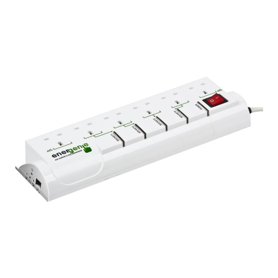
- Page 6 POWER MANAGEMENT SYSTEM - LAN 2. Indicators and controls of the PMS-LAN Managed sockets Main rocker switch RJ45 socket 120430 All brands and logos are registered trademarks of their respective owners...
-
Page 7: Side Panels
POWER MANAGEMENT SYSTEM - LAN 2.1. Side panels Figure 2 120430 All brands and logos are registered trademarks of their respective owners... - Page 8 POWER MANAGEMENT SYSTEM - LAN 2.2. Indicators Main rocker switch Z (Figure 1 above) is illuminated - the PMS-LAN is connected to the power supply and active. Power indicator (Figure 1 above) is illuminated. The non- manageable sockets (marked with the sign ) are switched on.
- Page 9 Circuit breaker. Pressing this button will reset the circuit breaker protective device if it has been tripped. Reset button (A). The PMS-LAN can be restarted if it can’t be accessed or works abnormally. All the IP settings and device settings will remain the same as before, but the server time will become outdated and all schedules will be reset.
- Page 10 (or your computer LAN card) with the provided patch cord or vice-versa. The PMS-LAN can now be switched on and off by means of the Main rocker switch (Z). The first and the last sockets of the PMS-LAN are marked with the symbol .
- Page 11 3 seconds. To protect the connected devices from possible high current and short circuit, the PMS-LAN is equipped with an automatic circuit breaker. 120430 All brands and logos are registered trademarks of their respective owners...
- Page 12 Remove the excessive load and then press the Circuit breaker button to restore the power supply (Figure 2 above). To be able to use PMS-LAN you will now have to complete its LAN configuration. 3.2. Obtaining an IP address.
- Page 13 (see Figure 2 above) with the tip of a pen and turn the Main rocker switch Z on. Wait for about 3 seconds until you hear the sockets switching twice. This procedure will force the PMS-LAN to reset itself to the default settings below ... IP: 192.168.0.254 Subnet mask: 255.255.255.0...
-
Page 14: Power Manager Installation
POWER MANAGEMENT SYSTEM - LAN ... PMS-LAN then searches for an IP address from your eventual DHCP server. If no DHCP server is found within 1 minute, PMS-LAN will then automatically revert to the default settings (see above, with IP address 192.168.0.254). - Page 15 Adapter subnet fields. Now press the Search button. Note: only PMS-LAN within a local subnet can be found. If your computer LAN adapter is not in the (default) subnet of PMS-LAN (as may be the case if you chose option B section 3.2) you will have to change its IP address manually to be able to find PMS- LAN.
- Page 16 POWER MANAGEMENT SYSTEM - LAN Figure 4 The window of your default internet browser will be then opened to give you access to the built-in web-server. See section 4 below for the further details. 120430 All brands and logos are registered trademarks of their respective owners...
- Page 17 POWER MANAGEMENT SYSTEM - LAN 4. The web server The PMS-LAN is equipped with a web-server which allows it to be managed using a web browser such as Internet Explorer, Firefox etc. 4.1. Web-server login page To access the web server of PMS-LAN, just open Internet Explorer (or other browser) and input the IP address of PMS-LAN (for example http://192.168.1.241).
- Page 18 IP configuration. 4.2. EnerGenie page With the help of EnerGenie page (see Figure 6 below) you will be able to see the status of all your four manageable sockets, and to switch the sockets on and off manually. The status of your sockets, as well as the buttons to switch them on/off are located at the top of the page.
- Page 19 (regardless whether you created a new or used an existing account) your PMS-LAN is automatically registered. 2. Return back to the EnerGenie page of your PMS-LAN (see Figure 6 below). Push Activate button to let the device initiate communication with EnerGenie.com server. The EnerGenie page will then start updating itself until the Status becomes Registered Activated Connected (see Figure 6 below).
- Page 20 POWER MANAGEMENT SYSTEM - LAN Figure 6 120430 All brands and logos are registered trademarks of their respective owners...
- Page 21 If you decide to stop managing your PMS-LAN via the Internet, use the Deactivate button to stop communication with the EnerGenie.com server. You can change the registration of your PMS-LAN and assign it to another account via the EnerGenie.com website (see section 5 below).
- Page 22 POWER MANAGEMENT SYSTEM - LAN Figure 7 120430 All brands and logos are registered trademarks of their respective owners...
- Page 23 POWER MANAGEMENT SYSTEM - LAN The socket shown in Figure #7 is currently off. It will turn on automatically on the 14th of January at 10:15 and switch off at 18:00. The two events will be executed with a loop period of 1 day.
- Page 24 POWER MANAGEMENT SYSTEM - LAN Figure 8 120430 All brands and logos are registered trademarks of their respective owners...
- Page 25 On the Socket name settings page (see Figure 9 below) you can assign suitable names to the sockets. These names will be shown on the EnerGenie page and on the Socket pages. Note: The maximum socket name length is 11 characters.
- Page 26 POWER MANAGEMENT SYSTEM - LAN Figure 9 120430 All brands and logos are registered trademarks of their respective owners...
- Page 27 POWER MANAGEMENT SYSTEM - LAN 4.5. LAN settings page Figure 10 120430 All brands and logos are registered trademarks of their respective owners...
- Page 28 DHCP server so that it always provides the same IP address to PMS-LAN. To do that you will need to know the MAC address of PMS-LAN. It can be found on this page or on the bottom sticker of the device. The MAC address is fixed and cannot be changed.
- Page 29 Manager software, normally it is not needed to change this setting. 4.6. Device settings page On the device settings page you can setup name, password and internal time of the PMS-LAN (Figure 11 below). 120430 All brands and logos are registered trademarks of their respective owners...
- Page 30 POWER MANAGEMENT SYSTEM - LAN Figure 11 120430 All brands and logos are registered trademarks of their respective owners...
- Page 31 4.5 above). 2. Server name can be convenient to identify the web server if you have more than one PMS-LAN. It is “Server 1” by default. 3. The password is necessary to access PMS-LAN both from your web browser and the Power Manager software (see section 6 below).
- Page 32 5. EnerGenie.com device interface With your free personal account at EnerGenie.com website you will be able to access your PMS-LAN from anywhere in the world using any Internet-enabled device (desktop PC, laptop, smartphone etc). See section 4.2 above on how to register your PMS-LAN on the server and setup the connection.
- Page 33 POWER MANAGEMENT SYSTEM - LAN 5.1. Logging in To login into your EnerGenie account just open the webpage www.energenie.com/user in your Internet browser and enter your login and password in the login window (see Figure 12 below). Figure 12 120430...
- Page 34 POWER MANAGEMENT SYSTEM - LAN This page will automatically update itself and will keep showing you the time when your device was last seen online (the latest time when the device communicated with the server) and the status of each socket. ...
- Page 35 POWER MANAGEMENT SYSTEM - LAN 6. POWER MANAGER SOFTWARE INSTALLATION This is available on the Power Manager CD supplied with the unit. 6.1. Finding the PMS-LAN Install Power Manager software v.4.0.0.0 (or higher) on a PC connected to your local network.
- Page 36 POWER MANAGEMENT SYSTEM - LAN Figure 13 The LAN devices window (see Figure 14 below) will appear, click the Add button to add a new PMS-LAN device. 120430 All brands and logos are registered trademarks of their respective owners...
- Page 37 POWER MANAGEMENT SYSTEM - LAN Figure 14 In the Add LAN device window (see Figure 15 below) enter the correct IP address, port number (5000 by default) and password (1 by default) as configured on the Device settings page (see section 4.6 above) of the web server.
- Page 38 POWER MANAGEMENT SYSTEM - LAN Figure 15 Specified device should then appear with a green square next to it and Connected status in the LAN devices window (see Figure 16 below). 120430 All brands and logos are registered trademarks of their respective owners...
- Page 39 POWER MANAGEMENT SYSTEM - LAN Figure 16 To edit the LAN device, select it and click the Edit button, or just double click on the LAN device To remove the LAN device, select it and click the Remove button. You can select multiple LAN devices using Ctrl and Shift keys.
- Page 40 POWER MANAGEMENT SYSTEM - LAN If the status of PMS-LAN shows the device not to be Connected - it could be due to the following reasons: Incorrect IP/Port/Password specified in the Add LAN device window PC is not connected to the local network You are trying to access PMS-LAN from the PC which is not...
- Page 41 POWER MANAGEMENT SYSTEM - LAN Figure 17 PMS-LAN is connected to local network (ping test is ok) but not responding. Reset PMS-LAN by pressing the Reset button (A) on the side control panel (see Figure 2 above) or switch it off and then on again (see Figure 1 above).
- Page 42 6.2. Managing the PMS-LAN After successful connection, close LAN devices window. You can now start managing PMS-LAN via the Power Manager interface. Double click on the socket icon in the system tray or select Open from the popup menu (see Figure 13 above). You will get the window of the main control panel shown on the Figure 18below.
- Page 43 POWER MANAGEMENT SYSTEM - LAN Figure 18 120430 All brands and logos are registered trademarks of their respective owners...
- Page 44 POWER MANAGEMENT SYSTEM - LAN Double clicking on a socket will switch it on and off (green color means the socket is switched off; red color means the socket is switched on). Click the Settings button for each socket to access the Settings dialog box (see Figure 19 below).
- Page 45 POWER MANAGEMENT SYSTEM - LAN It is possible name a device and socket (for example Printer or Scanner) using the Rename button Check the System tray checkbox if you want to put the icon of the socket into the system tray. You can choose the icon from drop down list box.
- Page 46 POWER MANAGEMENT SYSTEM - LAN 7. Power Manager Core Features 7.1 Setting up the hardware schedule Using the Hardware schedule button available from the Settings window you can create the hardware timer schedule (see Figure 20 below). To add a new record, click the Add button. 120430 All brands and logos are registered trademarks of their respective owners...
- Page 47 POWER MANAGEMENT SYSTEM - LAN Figure 20 The window Add entry will appear (see Figure 21 below). In the dialog box, specify the required time and the action 120430 All brands and logos are registered trademarks of their respective owners...
- Page 48 POWER MANAGEMENT SYSTEM - LAN Figure 21 To edit the record, select it and click the Edit button or just double click on the entry. The window Edit entry will appear (see Figure 22 below) 120430 All brands and logos are registered trademarks of their respective owners...
- Page 49 POWER MANAGEMENT SYSTEM - LAN Figure 22 To remove the record, select it and click the Remove button (see Figure 20 above). You can select multiple entries using Ctrl and Shift keys. You can also remove all entries from the schedule by clicking the Clear button (see Figure 20 above) ...
- Page 50 POWER MANAGEMENT SYSTEM - LAN Figure 23 After the schedule record has been created, click the Apply button (see Figure 20 above) to save the hardware timer schedule changes. In case of incorrect entries, these will be highlighted and an error message will appear. Click the Apply button again after correcting all the errors ...
- Page 51 However the whole schedule will be then delayed by the duration of the power cut off. The PMS-LAN will start beeping indicating a hardware schedule problem. Press the “Silence” button once to turn the beeper off if you wish to ignore the delay in the schedule.
-
Page 52: Setting Up The Software Schedule
POWER MANAGEMENT SYSTEM - LAN 7.2 Setting up the software schedule Use the Software schedule button available on the Settings window to create a software timer schedule (see Figure 24 below). Note: the software timer schedule will only be executed if the managing computer is on and the Power Manager is launched. - Page 53 POWER MANAGEMENT SYSTEM - LAN To add a new task, click the Add button. The Add task window will appear (see Figure 25 below) Figure 25 In the Add task window, check Switch ON time and/or Switch OFF time checkboxes and specify the time to switch the socked on and/or off.
- Page 54 POWER MANAGEMENT SYSTEM - LAN disable the task, uncheck the Enabled checkbox and to enable the task again, re-check the checkbox. To edit the task, select it (see Figure 25 above) and click the Edit button or just double click on the task. The Edit task window will appear (see Figure 26 below) Figure 26 120430...
- Page 55 POWER MANAGEMENT SYSTEM - LAN To remove the task, select it and click the Remove button (see Figure 20 above). You may select multiple tasks using Ctrl and Shift keys. You can also remove all tasks by clicking the Clear button Hint: Use the popup menu which can be activated by the right mouse button click over the table (see Figure 25 above).
- Page 56 POWER MANAGEMENT SYSTEM - LAN 120430 All brands and logos are registered trademarks of their respective owners...
- Page 57 POWER MANAGEMENT SYSTEM - LAN Figure 27 To add a new program event, click the Add app button. The Add program event dialog will appear (see Figure 28 below) 120430 All brands and logos are registered trademarks of their respective owners...
- Page 58 POWER MANAGEMENT SYSTEM - LAN Figure 28 Specify the application title and path to it using the Browse (…) button or typing it manually in the Title and Path name fields. If you use the Browse (…) button you can also select a shortcut to the application.
- Page 59 POWER MANAGEMENT SYSTEM - LAN specified the application, check On run and/or On exit and choose the event (switch on or off). Note: The On run event will take place when the first window of the selected application is opened. The On exit event will take place when the last window of the application is closed.
- Page 60 POWER MANAGEMENT SYSTEM - LAN Figure 29 Specify the path to the folder you would like to monitor using the Browse (…) button or typing it manually in the Path name field. Specify the File name mask using wildcard characters: *, ?. Check then On placing and/or On removal checkboxes and select the event and delay.
- Page 61 POWER MANAGEMENT SYSTEM - LAN Hint: Your device is an advanced standby-killer. Use the Add folder button to assign c:\\system32\\spool\\printers folder to switch your printer on whenever you start printing and to switch it off again whenever you are ready with printing. Hint: If you have several printers connected to the same computer, we suggest moving default spool directory of each printer to a separate location.
- Page 62 POWER MANAGEMENT SYSTEM - LAN Figure 30 To remove the event, select it and click the Remove button (see Figure 27 above). You can select multiple events using Ctrl and Shift keys. You can also remove all events by clicking the Clear button HINT: Use the popup menu which can be activated by the right mouse button click over the table.
- Page 63 8. Power Manager advanced features The following information is for advanced users which wish to have full access to the advanced features of the PMS-LAN. Click the Advanced features button available from the Settings window (see section 6.1 above). The following window will then appear (see Figure 31 below).
- Page 64 POWER MANAGEMENT SYSTEM - LAN 8.1. Processing the alarms Whenever the actual measured voltage on the manageable socket deviates from the status set by your switching tasks, it is called a Voltage alarm. The Voltage alarm can for example be caused by a blackout and will be resolved after power returns.
- Page 65 (see above) is resolved 8.2. Setting up network devices To avoid other users having to access the PMS-LAN via the IP address, it can be declared as a shared device on the server. To make the PMS-LAN shared on your computer press the button Device sharing...
- Page 66 Note: Port 6100 should be open. Contact your LAN administrator for further details. To be able to use this shared PMS-LAN on a client PC choose Shared devices from the Main menu (see Figure 13 above). You will get the following window (see Figure 34 below).
- Page 67 POWER MANAGEMENT SYSTEM - LAN Figure 34 To add a new remote device, press the Add button. You will see the window Add network device (see Figure 35 below). 120430 All brands and logos are registered trademarks of their respective owners...
- Page 68 Figure 35 Enter the network name of the server which is connected to the PMS-LAN in the field Hostname. Enter the name of the target PMS-LAN in the field Device name. Enter access password in the field Password. To disconnect from the device uncheck the option Enable, set this option on again to regain the access.
- Page 69 POWER MANAGEMENT SYSTEM - LAN box Find network device will appear. Choose the proper server and then the device and click OK button. To edit the network device, select it and click the Edit button, or just double click on the network device (see Figure 34 above). The Edit network device window will appear (see Figure 36 below).
- Page 70 HINT: Use the popup menu which is available with the right mouse button click over the table. 8.3. Managing the PMS-LAN via your own software To let you switch the sockets from your own applications the following command line interface syntax is supported: ...
- Page 71 POWER MANAGEMENT SYSTEM - LAN Execute pm.exe with -info key (pm.exe –info) to get the complete information about the status of the current devices. For each of the connected devices the following information will then be provided and placed into Info.ini file in the Power Manager folder: ...
-
Page 72: Troubleshooting
Make sure PMS-LAN is connected to lost. It seems something is LAN and switched on. Launch Find PMS-LAN utility. You can also try to wrong with its IP address. 120430 All brands and logos are registered trademarks of their respective owners... -
Page 73: Frequently Asked Questions
Q: What appliances can I use this extension lead for? Answer: As it is 13A rated, it can be used with any household device. Q: Can the PMS-LAN unit be used outside? Answer: No, this product is for indoor use only. Q: Can each socket be programmed individually? Answer: Yes, there are four sockets that are controlled separately. - Page 74 POWER MANAGEMENT SYSTEM - LAN A: No the unit has internal hardware timers for each controlled socket that allows it to operate disconnected from the computer once it has been programmed. Q. I am having trouble connecting to my device via the internet. It just says Activated.
- Page 75 NAT configuration allows this). Please check the DNS server has been set up as in the previous question. www.energenie4u.co.uk Energenie is a trading name of Sandal plc, Claremont House, Deans Court, Bicester, Oxon, OX26 6BW ©2012 120430 All brands and logos are registered trademarks of their respective owners...
- Page 76 POWER MANAGEMENT SYSTEM - LAN 120430 All brands and logos are registered trademarks of their respective owners...
Need help?
Do you have a question about the PMS-LAN and is the answer not in the manual?
Questions and answers