Table of Contents
Advertisement
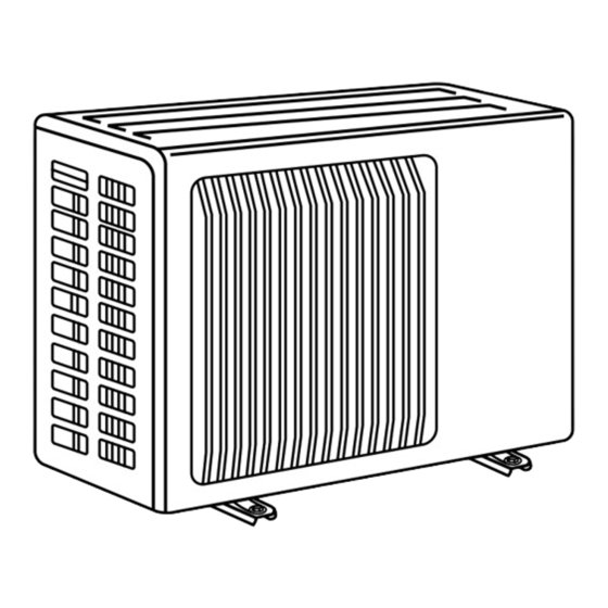
SPLIT-TYPE AIR CONDITIONERS
OUTDOOR UNIT
SERVICE MANUAL
Models
MU-A18ND-
MU-A18ND-
MU-A24ND-
MU-A24ND-
MU-A30ND-
MU-A30ND-
NOTE:
• This service manual describes technical data of the outdoor units.
• RoHS compliant products have <G> mark on the spec name plate.
For servicing of RoHS compliant products, refer to the RoHS Parts List.
S1
S2
S1
S2
S1
S2
MU-A18ND
• SPECIFICATION has been modified.
Please void OB405 REVISED EDITION-D.
Indoor unit service manual
CONTENTS
1. TECHNICAL CHANGES ····································2
2. PART NAMES AND FUNCTIONS······················3
3. SPECIFICATION·················································3
4. OUTLINES AND DIMENSIONS ·························4
5. WIRING DIAGRAM ············································6
6. REFRIGERANT SYSTEM DIAGRAM ················8
7. PERFORMANCE CURVES ······························10
8. TROUBLESHOOTING······································12
9. DISASSEMBLY INSTRUCTIONS ····················21
10. PARTS LIST······················································27
11. RoHS PARTS LIST···········································30
No. OB405
REVISED EDITION-E
MS-A
ND Series (OB404)
•
TM
Advertisement
Table of Contents
Troubleshooting

Subscribe to Our Youtube Channel
Related Manuals for Mitsubishi Electric Mr.Slim MU-A18ND-S1


Summary of Contents for Mitsubishi Electric Mr.Slim MU-A18ND-S1
-
Page 1: Table Of Contents
Revision E: • SPECIFICATION has been modified. Please void OB405 REVISED EDITION-D. SPLIT-TYPE AIR CONDITIONERS OUTDOOR UNIT No. OB405 SERVICE MANUAL REVISED EDITION-E Models MU-A18ND- MU-A18ND- MU-A24ND- MU-A24ND- MU-A30ND- MU-A30ND- Indoor unit service manual MS-A ND Series (OB404) • CONTENTS 1. -
Page 2: Technical Changes
Revision A: • Check of solenoid valve coil has been partially modified. Revision B: • MU-A24ND has been added. Revision C: • MU-A18ND has been added. Revision D: • MU-A30ND has been added. Revision E: • SPECIFICATION has been modified. TECHNICAL CHANGES w : change Frequency... -
Page 3: Part Names And Functions
PART NAMES AND FUNCTIONS OUTDOOR UNIT MU-A24ND MU-A30ND MU-A18ND Air inlet (back and side) Air inlet Piping Drain hose Air outlet Air outlet Drain outlet SPECIFICATION Outdoor model MU-A18ND MU-A24ND MU-A30ND Function Cooling Single phase 220-230V, 60Hz Power supply ISO 5151 SSA 385 ISO 5151 SSA 385... -
Page 4: Outlines And Dimensions
OUTLINES AND DIMENSIONS MU-A18ND - REQUIRED SPACE Unit: mm OUTDOOR UNIT Drainage hole [16.2 Air in Air in Drainage Air out 3holes [33 Service panel Liquid refrigerant pipe joint Refrigerant pipe (Flared) [6.35 Gas refrigerant pipe joint Refrigerant pipe (flared) [12.7 MU-A18ND - REQUIRED SPACE Drainage... - Page 5 MU-A24ND MU-A30ND OUTDOOR UNIT Open as a rule REQUIRED SPACE 500mm or more if the front and both sides are open 100mm or more 200mm or more if 100mm or more there are obstacles to both sides Open as a rule 500mm or more if the back, 350mm or more both sides and top are open...
-
Page 6: Wiring Diagram
WIRING DIAGRAM MU-A18ND OUTDOOR UNIT 220-230V~ ORANGE WHITE BLACK 220-230V~ GRN/YLW SYMBOL NAME SYMBOL NAME SYMBOL NAME TERMINAL BLOCK COMPRESSOR CAPACITOR FUSE (3.15A) OUTDOOR FAN CAPACITOR COMPRESSOR(INNER PROTECTOR) TERMINAL BLOCK DSAR SURGE ABSORBER OUTDOOR FAN MOTOR(INNER PROTECTOR) NOTES: 1.About the indoor side electric wiring refer to the indoor unit electric wiring diagram for servicing. 2.Use copper conductors only (For field wiring). - Page 7 MU-A24ND- OUTDOOR UNIT 220-230V~ 220-230V~ DSAR SYMBOL NAME SYMBOL NAME SYMBOL NAME COMPRESSOR CAPACITOR TERMINAL BLOCK FUSE(3.15A) OUTDOOR FAN CAPACITOR TERMINAL BLOCK COMPRESSOR(INNER PROTECTOR) SURGE ABSORBER COMPRESSOR CONTACTOR DSAR OUTDOOR FAN MOTOR(INNER PROTECTOR) NOTES: 1.Use copper conductors only (For field wiring). 2.Since the indoor and outdoor unit connecting wires have polarity, connect them according to the numbers (2,N,L).
-
Page 8: Refrigerant System Diagram
REFRIGERANT SYSTEM DIAGRAM MU-A18ND Unit : mm OUTDOOR UNIT Refrigerant pipe {12.7 (with heat insulator) Stop Valve (with service port) Outdoor heat exchanger Strainer Compressor Flared connection Capillary tube Stop Valve [3.0 x [1.8 x 400 Refrigerant pipe {6.35 (with heat insulator) MU-A24ND OUTDOOR UNIT Refrigerant pipe... - Page 9 MU-A30ND Unit : mm OUTDOOR UNIT Refrigerant pipe [15.88 Strainer (with heat insulator) #100 Stop valve (with service port) Outdoor heat Discharge Flared connection exchanger temperature thermistor RT62 Accumulator Compressor Ambient temperature Capillary tube thermistor [4.0 x [2.4 x 200 RT63 [4.2 x [3.0 x 50 Solenoid valve...
-
Page 10: Performance Curves
PERFORMANCE CURVES MU-A18ND MU-A24ND MU-A30ND The standard data contained in these specifications apply only to the operation of the air conditioner under normal conditions. Since operating conditions vary according to the areas where these units are installed. The following information has been provided to clarify the operating characteristics of the air conditioner under the conditions indicated by the performance curve. - Page 11 OUTDOOR LOW PRESSURE AND OUTDOOR UNIT CURRENT COOL operation x Both indoor and outdoor units are under the same temperature/humidity condition. Relative humidity (%) Dry-bulb temperature (:) ➁ Air flow should be set at MAX. 3 The unit of pressure has been changed to MPa on the international system of units(SI unit system). The conversion factor is : 1(MPa [Gauge]) =10.2(kgf/f f [Gauge]) MU-A18ND...
-
Page 12: Troubleshooting
MU-A30ND MU-A30ND (kgf/F[Gauge])(MPa[Gauge]) 15.0 14.0 13.0 12.0 11.0 10.0 18 20 30 32 35(:) 18 20 30 32 35(:) Ambient temperature (˚C)/Ambient humidity (%) Ambient temperature (˚C)/Ambient humidity (%) TROUBLESHOOTING MU-A18ND MU-A24ND MU-A30ND 8-1. Cautions on troubleshooting 1. Before troubleshooting, check the following: 1) Check the power supply voltage. - Page 13 8-2. Instruction of troubleshooting Start Indoor unit Indoor unit Indoor unit OPERATION INDICATOR operates. operates. dose not receive Outdoor unit lamp on the indoor unit is Outdoor unit the signal from dose not operate flashing on and off. dose not remote controller.
- Page 14 8-3. Trouble criterion of main parts MU-A18ND MU-A24ND MU-A30ND Part name Check method and criterion Figure Measure the resistance with a tester. Before measurement, hold the thermistor with your hands to warm it up. Discharge temperature (Part temperature 0˚C ~ 40˚C) thermistor(RT62) Refer to 8-5.
-
Page 15: Troubleshooting Flow
8-4. Troubleshooting flow Compressor and / or outdoor fan motor dose not operate. Check of outdoor unit MU-A30ND Turn ON the power supply. Is there 220-230V AC to Check the outdoor power supply between on the and connection of wiring. outdoor terminal block Compressor dose not operate. - Page 16 Compressor and / or outdoor fan motor dose not stop. Check of outdoor unit MU-A24ND - 1 Turn OFF the power supply. 2 After 30 seconds, turn ON the power supply again. 3 Operate the unit in COOL mode by pressing the EMERGENCY OPERATION switch.
- Page 17 When OPERATION INDICATOR lamp flashes ON and OFF in every 0.5-second. Outdoor unit dose not operate. w Short circuit of JPG and JPS on the indoor electronic control How to check mis-wiring MU-A30ND P.C. board enables self -check to be displayed in 3 seconds. Start •...
-
Page 18: Check Of Lev (Expansion Valve)
When OPERATION INDICATOR lamp flashes 10-time. Cooling mode dose not operate. Check of LEV (Expansion valve) MU-A30ND Remote controller model : KP0B Remote controller model : KM04B Turn ON the power supply. Turn ON the power supply. 1 While pressing OPERATION 1 While pressing both OPERATION KP0B KM04B... - Page 19 Check of solenoid valve coil MU-A30ND Outdoor unit repeats start and stop. Turn ON the power supply. Operate the unit in COOL mode by pressing the EMERGENCY OPERATION switch. After 1minute or more has passed since the compressor started, operate the solenoid valve coil by heating or cooling the ambient temperature thermistor.
- Page 20 8-5. Test point diagram and voltage MU-A30ND Outdoor deicer P.C. board Ambient temperature thermistor (RT63) Discharge temperature thermistor(RT62) -20 -10 10 20 30 40 0 10 20 30 40 50 60 70 80 90 100 110 120 Temperature(:) Temperature(:) CN662 1-2 CN662 3-4 Discharge temperature Ambient tempera-...
-
Page 21: Disassembly Instructions
DISASSEMBLY INSTRUCTIONS <"Terminal with locking mechanism" Detaching points> The terminal which has the locking mechanism can be detached as shown below. There are two types ( Refer to (1) and (2)) of the terminal with locking mechanism. The terminal without locking mechanism can be detached by pulling it out. Check the shape of the terminal before detaching. - Page 22 PHOTOS OPERATING PROCEDURE 2. Removing the electrical parts Photo 3 (1) Remove the service panel and the cabinet. Outdoor fan capacitor(C2) (2) Remove the following parts. •Compressor capacitor (C1) •Outdoor fan capacitor (C2) •Terminal blocks (TB1,TB2) Terminal Compressor capacitor(C1) blocks(TB1,TB2) Photo 4 Hook 3.
- Page 23 9-2. MU-A24ND OUTDOOR UNIT OPERATING PROCEDURE PHOTOS 1.Removing the cabinet Photo 1 Screw of the top panel (1) Remove the screw of the service panel. (2) Remove the screws of the top panel. (3) Remove the screw of the valve cover. (4) Remove the service panel.
- Page 24 OPERATING PROCEDURE PHOTOS 3. Removing the propeller and the outdoor fan motor Photo 5 (1) Remove the cabinet. (Refer to 1.) (2) Remove the propeller nut and the propeller. NOTE : Loose the propeller in the rotating direction for Set screws of the removal.
- Page 25 9-3. MU-A30ND OUTDOOR UNIT OPERATING PROCEDURE PHOTOS 1.Removing the cabinet Photo 1 Screw of the top panel (1) Remove the screw of the service panel. (2) Remove the screws of the top panel. (3) Remove the screw of the valve cover. (4) Remove the service panel.
- Page 26 OPERATING PROCEDURE PHOTOS 3. Removing the propeller and the outdoor fan motor Photo 5 (1) Remove the cabinet. (Refer to 1.) (2) Remove the propeller nut and the propeller. NOTE : Loose the propeller in the rotating direction for Set screws of the removal.
-
Page 27: Parts List
PARTS LIST (non-RoHS compliant) MU-A18ND 10-1. OUTDOOR UNIT STRUCTURAL PARTS, ELECTRICAL PARTS AND FUNCTIONAL PARTS Part numbers that are circled are not shown in the illustration. Q'ty/unit Symbol in Wiring Part No. Part Name Remarks MU-A18ND - MU-A18ND - Diagram E02 817 233 BACK PANEL E02 A27 233... - Page 28 PARTS LIST (non-RoHS compliant) MU-A24ND MU-A30ND 10-2. OUTDOOR UNIT STRUCTURAL PARTS, ELECTRICAL PARTS AND FUNCTIONAL PARTS...
- Page 29 PARTS LIST (non-RoHS compliant) MU-A24ND MU-A30ND 10-2. OUTDOOR UNIT STRUCTURAL PARTS, ELECTRICAL PARTS AND FUNCTIONAL PARTS Part numbers that are circled are not shown in the illustration. Q'ty/unit Symbol Remarks Part No. Part Name in Wiring Diagram A24ND - A24ND - A30ND - E02 819 297 TOP PANEL...
-
Page 30: Rohs Parts List
RoHS PARTS LIST (RoHS compliant) MU-A18ND 11-1. OUTDOOR UNIT STRUCTURAL PARTS, ELECTRICAL PARTS AND FUNCTIONAL PARTS... - Page 31 RoHS PARTS LIST (RoHS compliant) MU-A18ND 11-1. OUTDOOR UNIT STRUCTURAL PARTS, ELECTRICAL PARTS AND FUNCTIONAL PARTS Part numbers that are circled are not shown in the illustration. Q'ty/unit Symbol in Wiring Part No. Part Name Remarks MU-A18ND - MU-A18ND - Diagram E12 817 233 BACK PANEL...
- Page 32 RoHS PARTS LIST (RoHS compliant) MU-A24ND MU-A30ND 11-2. OUTDOOR UNIT STRUCTURAL PARTS, ELECTRICAL PARTS AND FUNCTIONAL PARTS...
- Page 33 RoHS PARTS LIST (RoHS compliant) MU-A24ND MU-A30ND 11-2. OUTDOOR UNIT STRUCTURAL PARTS, ELECTRICAL PARTS AND FUNCTIONAL PARTS Part numbers that are circled are not shown in the illustration. Q'ty/unit Symbol Remarks Part No. Part Name in Wiring A24ND - A24ND - A30ND - A30ND - Diagram...
- Page 36 HEAD OFFICE: TOKYO BLDG, 2-7-3, MARUNOUCHI, CHIYODAKU, TOKYO 100-8310, JAPAN C C Copyright 2005 MITSUBISHI ELECTRIC ENGINEERING CO.,LTD Distributed in Oct. 2009. No.OB405 REVISED EDITION-E 5 Distributed in May 2006. No.OB405 REVISED EDITION-D 106 Distributed in Nov. 2005. No.OB405 REVISED EDITION-C 106 Distributed in Jun.
Need help?
Do you have a question about the Mr.Slim MU-A18ND-S1 and is the answer not in the manual?
Questions and answers