Mitsubishi Electric Mr. Slim MS-A09WA Service Manual
Split-type air conditioners
Hide thumbs
Also See for Mr. Slim MS-A09WA:
- Service manual (36 pages) ,
- Operating instructions manual (33 pages) ,
- Installation manual (9 pages)
Table of Contents
Advertisement
INDOOR UNIT
SERVICE MANUAL
Models
MS-A09WA
MS-A09WA -
MS-A12WA
MS-A12WA -
NOTE:
RoHS compliant products have <G> mark on the spec name plate.
For servicing of RoHS compliant products, refer to the RoHS PARTS
LIST (RoHS compliant).
• TEST POINT DIAGRAM AND VOLTAGE has
Please void OB448 REVISED EDITION-B.
1
1
CONTENTS
1. TECHNICAL CHANGES ··································· 2
2. PART NAMES AND FUNCTIONS ····················· 3
3. SPECIFICATION ················································ 5
4. OUTLINES AND DIMENSIONS ························ 6
5. WIRING DIAGRAM ············································ 7
6. REFRIGERANT SYSTEM DIAGRAM ··············· 7
7. SERVICE FUNCTIONS ····································· 8
8. TROUBLESHOOTING ······································· 9
9. DISASSEMBLY INSTRUCTIONS ···················· 21
10. PARTS LIST ····················································· 24
10-1. PARTS LIST ············································· 24
10-2. RoHS PARTS LIST ·································· 27
11. MICROPROCESSOR CONTROL ···················· 30
been corrected. (8-7)
No. OB448
REVISED EDITION-C
Outdoor unit service manual
MU-A•WA Series (OB449)
Advertisement
Table of Contents
Troubleshooting

Subscribe to Our Youtube Channel
Related Manuals for Mitsubishi Electric Mr. Slim MS-A09WA


Summary of Contents for Mitsubishi Electric Mr. Slim MS-A09WA
-
Page 1: Table Of Contents
Revision C: • TEST POINT DIAGRAM AND VOLTAGE has been corrected. (8-7) Please void OB448 REVISED EDITION-B. INDOOR UNIT No. OB448 SERVICE MANUAL REVISED EDITION-C Models MS-A09WA MS-A09WA - MS-A12WA MS-A12WA - Outdoor unit service manual MU-A•WA Series (OB449) CONTENTS 1. -
Page 2: Technical Changes
Revision A : • MS-A•WA- have been added. Remote controller has been changed. Revision B : • SPECIFICATION has been corrected. Powerful has been added. (Airflow ,Sound level) Revision C: • TEST POINT DIAGRAM AND VOLTAGE has been corrected. (8-7) TECHNICAL CHANGES MS09TW MS-A09WA... -
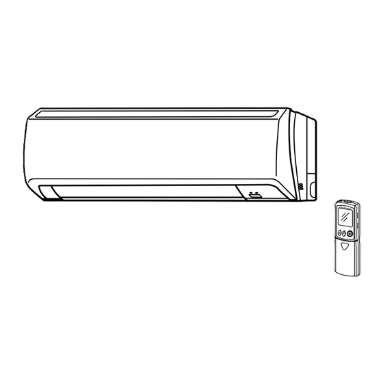
Page 3: Part Names And Functions
PART NAMES AND FUNCTIONS MS-A09WA MS-A12WA Air inlet Heat exchanger Front panel Panel Air cleaning filter (Anti-Allergy Enzyme Filter, Blue bellows type) Catechin air filter Air outlet Vertical vane Horizontal vane Remote controller Line flow fan Display section Operation section (When the front panel is opened) Operation Indicator lamp... - Page 4 MS-A09WA MS-A12WA ACCESSORIES MS-A09/12WA MS-A09/12WA- Installation plate Installation plate fi xing screw 4 × 25 mm Remote controller holder Fixing screw for 3.5 × 1.6 mm (Black) Battery (AAA) for remote controller Wireless remote controller Felt tape (Used for left or left-rear piping) Conduit plate —...
-
Page 5: Specification
SPECIFICATION Model MS-A09WA MS-A12WA Indoor unit model MS-A09WA MS-A12WA External fi nish White Power supply V, phase, Hz 115, 1, 60 Max.-fuse size (time delay) / Disconnect switch Min. circuit ampacity Fan motor F.L.A 0.95 Airfl ow COOL 183 - 261 - 335 - 367 222 - 286 - 406 - 446 Low–Med.–High–Powerful Dry (Wet) -
Page 6: Outlines And Dimensions
OUTLINES AND DIMENSIONS Unit : inch MS-A09WA MS-A12WA Conduit plate(MS-A•WA- is excluded.) 7/16x1 Oblong hole 7/16x13/16 Oblong hole Installation plate 8-7/8 8-7/8 2-3/16 2-3/16 hole 30-11/16 6-1/8 6-1/8 1-3/4 2-3/4 2-3/16 13-3/16 12-5/8 Indoor unit Wall hole 2-9/16 Air in 3/16 8-1/4 Installation plate... -
Page 7: Wiring Diagram
WIRING DIAGRAM MS-A09WA MS-A12WA REFRIGERANT SYSTEM DIAGRAM MS-A09WA MS-A12WA Unit : inch Refrigerant pipe 3/8 (MS-A09) 1/2 (MS-A12) (with heat insulator) Indoor coil Indoor thermistor heat RT12 exchanger Flared connection Room temperature thermistor RT11 Flared connection Refrigerant pipe 1/4 Refrigerant flow in cooling (with heat insulator) -
Page 8: Service Functions
SERVICE FUNCTIONS MS-A09WA MS-A12WA 7-1. TIMER SHORT MODE For service, set time can be shortened by short circuit of JPG and JPS the electronic control P.C. board. The time will be shortened as follows. (Refer to 8-7.) Set time : 1-minute 1-second Set time : 3-minute 3-second (It takes 3 minutes for the compressor to start operation. -
Page 9: Troubleshooting
7-3. AUTO RESTART FUNCTION When the indoor unit is controlled with the remote controller, the operation mode, the set temperature, and the fan speed are memorized by the indoor electronic control P.C. board. The “AUTO RESTART FUNCTION” sets to work the moment power has restored after power failure. - Page 10 3. Troubleshooting procedure 1) First, check if the OPERATION INDICATOR lamp on the indoor unit is flashing on and off to indicate an abnormality. To make sure, check how many times the abnormality indication is flashing on and off before starting service work. 2) Before servicing check that the connector and terminal are connected properly.
-
Page 11: Failure Mode Recall Function
8-2. FAILURE MODE RECALL FUNCTION Outline of the function This air conditioner can memorize the abnormal condition which has occurred once. Even though LED indication listed on the troubleshooting check table (8-4.) disappears, the memorized failure details can be recalled. 1. - Page 12 2. Indoor unit failure mode table Abnormal point Left lamp of OPERATION Condition Correspondence INDICATOR lamp (Failure mode) Not lighted Normal — — The room temperature thermistor short or 1-time fl ash every Room temperature Refer to the characteristics of the room temperature open circuit is detected every 8 seconds dur- 0.5-second thermistor...
- Page 13 8-3. INSTRUCTION OF TROUBLESHOOTING Start Indoor unit Indoor unit oper- OPERATION INDICATOR ates. doesn't receive lamp on the indoor unit is the signal from Outdoor unit fl ashing on and off. doesn't operate. remote controller. If blinking of OPERATION INDI- CATOR lamp cannot be checked, it can be checked with failure mode recall function.
- Page 14 8-4. TROUBLESHOOTING CHECK TABLE Before taking measures, make sure that the symptom reappears for accurate troubleshooting. When the indoor unit has started operation and detected an abnormality of the following condition (the first detection after the power ON), the indoor fan motor turns OFF and OPERATION INDICATOR lamp flashes. OPERATION INDICATOR Lighted Blinking...
- Page 15 8-5. TROUBLE CRITERION OF MAIN PARTS MS-A09WA MS-A12WA Part name Check method and criterion Figure Room temperature thermistor Measure the resistance with a tester. (Part temperature 50 ~ 86°F) (RT11) Refer to 8-7. "Test point diagram and voltage", the chart of thermistor. Indoor coil thermistor (RT12) Indoor fan motor...
-
Page 16: Troubleshooting Flow
8-6. TROUBLESHOOTING FLOW A Check of indoor fan motor The indoor fan motor error has occurred, and the indoor fan doesn't operate. Turn OFF the power supply. Pay careful attention to the high voltage on the fan motor connector CN211. Turn ON the power supply, wait 5 seconds or more, and then press EMERGENCY OPERATION switch. - Page 17 B Check of remote controller and indoor electronic control P.C. board Check if the remote controller is exclusive for this air conditioner. Press OPERATE/STOP (ON/OFF) button on the remote controller. Is LCD display on the remote controller Replace the batteries. (Refer to 8-1.4.) visible? (Not clear) Remove the batteries, then set them back...
- Page 18 C Check of indoor electronic control P.C. board and indoor fan motor Turn OFF the power supply. Remove indoor fan motor connector CN211 Measure the resistance between and vane motor connector CN151 from the Short/open circuit: CN211 of the indoor fan motor indoor electronic control P.C.
- Page 19 D Electromagnetic noise enters into TV sets or radios Is the unit grounded? Ground the unit. Is the distance between the antennas Extend the distance between the antennas and and the indoor unit within 9.91 ft., or is the indoor unit, and/or the antennas and the the distance between the antennas and outdoor unit.
- Page 20 8-7. TEST POINT DIAGRAM AND VOLTAGE MS-A09WA MS-A12WA Indoor electronic control P.C. board Power supply input Varistor (NR11) 115 VAC Fuse (F11) 250 V 3.15 A Resistor (R111) Indoor fan motor (CN211) 162 VDC (-) Fiducial terminal of cathode side on measur- ing high-voltage DC 15 VDC (+)3-6 VDC...
-
Page 21: Disassembly Instructions
DISASSEMBLY INSTRUCTIONS <"Terminal with locking mechanism" Detaching points> The terminal which has the locking mechanism can be detached as shown below. There are two types (refer to (1) and (2)) of the terminal with locking mechanism. The terminal without locking mechanism can be detached by pulling it out. Check the shape of the terminal before detaching. - Page 22 OPERATING PROCEDURE PHOTOS 2. Removing the electronic control P.C. board, the Photo 4 power monitor receiver P.C. board, SW P.C. board and the terminal block (1) Remove the horizontal vane, the panel (refer to 1.) and the corner box. (2) Remove the screw of the conduit cover, and conduit cover. (Photo 2 or Photo 3) (3) Remove the indoor/outdoor connecting wire.
- Page 23 OPERATING PROCEDURE PHOTOS 4. Removing the horizontal vane motor unit Photo 7 (1) Remove the horizontal vane and the panel. (Refer to 1.) (2) Remove the screws of the horizontal vane motor unit, and pull out the horizontal vane motor unit. (Photo 7) Screws of the (3) Disconnect the connector from the horizontal vane motor horizontal vane...
-
Page 24: Parts List
PARTS LIST 10-1. PARTS LIST (non-RoHS compliant) MS-A09WA MS-A12WA 1. INDOOR UNIT STRUCTURAL PARTS 2. ACCESSORY AND REMOTE CONTROLLER (See 10-1.5.) 1. INDOOR UNIT STRUCTURAL PARTS Q'ty/unit Symbol Part No. Part name in Wiring Remarks MS-A09WA MS-A12WA Diagram 1 E02 A32 234 BOX 2 E02 A49 000 PANEL ASSEMBLY Including No.3,4 3 E02 913 067... - Page 25 MS-A09WA MS-A12WA 3. INDOOR UNIT ELECTRICAL PARTS AND FUNCTIONAL PARTS Q'ty/unit Symbol Part No. Part name in Wiring Remarks MS-A09WA MS-A12WA Diagram 1 E02 751 509 BEARING MOUNT 2 E02 001 504 SLEEVE BEARING 3 E02 897 702 DRAIN HOSE 4 E02 A49 235 NOZZLE ASSEMBLY 5 E02 897 303 VANE MOTOR UNIT (HORIZONTAL)
- Page 26 MS-A09WA MS-A12WA 4. INDOOR UNIT HEAT EXCHANGER Q'ty/unit Symbol Part No. Part name in Wiring Remarks MS-A09WA MS-A12WA Diagram E02 A49 620 INDOOR HEAT EXCHANGER E02 A50 620 E02 151 666 ø3/8 UNION (GAS) E02 155 666 ø1/2 3 E02 151 667 UNION (LIQUID) ø1/4 5.
-
Page 27: Rohs Parts List
10-2. RoHS PARTS LIST (RoHS compliant) MS-A09WA MS-A12WA 1. INDOOR UNIT STRUCTURAL PARTS 2. ACCESSORY AND REMOTE CONTROLLER (See 10-2.5.) 1. INDOOR UNIT STRUCTURAL PARTS Q'ty/unit Symbol Part No. Part name in Wiring MS-A09WA MS-A12WA Remarks Diagram G E12 A32 234 BOX G E12 A49 000 PANEL ASSEMBLY Including No.3,4 G E12 913 067 SCREW CAP... - Page 28 MS-A09WA MS-A12WA 3. INDOOR UNIT ELECTRICAL PARTS AND FUNCTIONAL PARTS Q'ty/unit Symbol Part No. Part name in Wiring MS-A09WA MS-A12WA Remarks Diagram G E12 751 509 BEARING MOUNT G E12 001 504 SLEEVE BEARING G E12 897 702 DRAIN HOSE G E12 A49 235 NOZZLE ASSEMBLY G E12 897 303 VANE MOTOR UNIT (HORIZONTAL) UP &...
- Page 29 MS-A09WA MS-A12WA 4. INDOOR UNIT HEAT EXCHANGER Q'ty/unit Symbol MS-A09WA MS-A12WA Part No. Part name in Wiring Remarks Diagram G E12 A49 620 INDOOR HEAT EXCHANGER G E12 A50 620 G E12 151 666 ø3/8 UNION (GAS) G E12 155 666 ø1/2 G E12 151 667 UNION (LIQUID) ø1/4...
-
Page 30: Microprocessor Control
MICROPROCESSOR CONTROL MS-A09WA MS-A12WA WIRELESS REMOTE CONTROLLER Signal transmitting section Operation display section ON/OFF (operate/ stop) button VANE button (Horizontal vane button) Fan speed control button Temperature buttons Off-timer button Operation select button ECONO COOL button On-timer button TIME set buttons Forward button Backward button Indication of... - Page 31 11-1. COOL ( ) OPERATION (1) Press OPERATE/STOP (ON/OFF) button. OPERATION INDICATOR lamp of the indoor unit turns on with a beep tone. (2) Select COOL mode with OPERATION SELECT button. (3) Press TEMPERATURE buttons (TOO WARM or TOO COOL button) to select the desired temperature. The setting range is 61 ~ 88°F.
- Page 32 (5) TEMPERATURE buttons In “I FEEL CONTROL” ( ) mode, set temperature is decided by the microprocessor based on the room temperature. In addition, set temperature can be controlled by TOO WARM or TOO COOL buttons when you feel too cool or too warm. Each time the TOO WARM or TOO COOL button is pressed, the indoor unit receives the signal and emits a beep tone.
- Page 33 (8) To change the airfl ow direction not to blow directly onto your body. To change When to use this function? COOL/DRY the airfl ow direction Pressing and holding VANE Use this function if you don’t The air conditioner starts the CONTROL button for 2 sec- want the air from the indoor unit cooling or drying operation ap-...
- Page 34 11-6. TIMER OPERATION 1. How to set the timer (1) Press OPERATE/STOP (ON/OFF) button to start the air conditioner. (2) Check that the current time is set correctly. NOTE : Timer operation will not work without setting the current time. Initially “0:00” blinks at the current time display of TIME MONITOR, so set the current time correctly with CLOCK SET button.
- Page 35 11-7. EMERGENCY/TEST OPERATION In case of test run operation or emergency operation, use EMERGENCY OPERATION switch on the front of the indoor unit. Emergency operation is available when the remote controller is missing, has failed or the batteries of the remote controller run down.
- Page 36 HEAD OFFICE: TOKYO BLDG., 2-7-3, MARUNOUCHI, CHIYODA-KU, TOKYO 100-8310, JAPAN Copyright 2006 MITSUBISHI ELECTRIC ENGINEERING CO.,LTD Distributed in Oct. 2008. No. OB448 REVISED EDITION-C 5 Distributed in Jun. 2008. No. OB448 REVISED EDITION-B 6 Distributed in May 2007. No. OB448 REVISED EDITION-A 7 New publication, effective Oct.
Need help?
Do you have a question about the Mr. Slim MS-A09WA and is the answer not in the manual?
Questions and answers