Scanreco G5 Pocket System Instruction Manual
Hide thumbs
Also See for G5 Pocket System:
- Instruction manual (34 pages) ,
- Instructions manual (6 pages)
Table of Contents
Advertisement
Advertisement
Table of Contents

Related Manuals for Scanreco G5 Pocket System


Summary of Contents for Scanreco G5 Pocket System
- Page 1 Instruction Manual G5 Pocket System Document Revision Language English 66060...
-
Page 3: Table Of Contents
Document type Document number Page Instruction Manual 66060 2 of 25 Contents General information..................4 Safety information..................5 General......................5 Pre-operation....................6 System information..................7 System overview..................7 Radio information..................8 G5 Pocket HCU....................9 Product description..................9 Versions.....................10 Functionality....................10 Changing battery..................11 Technical data HCU...................12 G5 Central Unit.....................13 Product describtion...................13 Versions......................14 Functionality....................14 Terminal schematics Central Unit............15... -
Page 4: Revision History
The text in this instruction manual, or any part of it may not be reproduced or transmitted in any form or by any means, including electronic, mechanical, photocopying, recording, storage in an information retrieval system, or otherwise, without prior written permis- sion of SCANRECO AB, SWEDEN. Revision history Revision... -
Page 5: General Information
General information This instruction manual describes the SCANRECO G5 Pocket system, this instruction manual should be seen as a complement to the instruction manual for the application which the SCANRECO G5 Pocket is intended to operate with. The SCANRECO G5 Pocket is a complete remote control system for mobile and stationary applica-... -
Page 6: Safety Information
SCANRECO instructions in this document. If the SCANRECO G5 Pocket will be used in a safety critical application, the purchaser / system installer must undertake appropriate testing and evaluation of the final application to prevent injury to the ultimate user. -
Page 7: Pre-Operation
In order to ensure safety of the operator, bystanders and the machine, the user should study and learn all provided instructions regarding how to use the SCANRECO G5 Pocket as well as all safety instructions and the location of all emergency stop controls. This will enable the user to quickly get familiar with the new remote control system and how to safely utilize it. -
Page 8: System Information
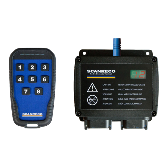
The system is protected against electromagnetic and radio frequency radiation. The G5 Pocket system is comprised of a Handheld Control Unit (HCU) with ON/OFF buttons. The Central Unit (CU) provides the connection points for connecting to the electro-hydraulic valves as well as through a CANopen bus system to other components of the control system. -
Page 9: Radio Information
Document type Document number Page Instruction Manual 66060 8 of 25 Radio information The G5 system family incorporates an automated frequency jumping technology, a reliable radio transmission highly resistant to interference. The radio transmission takes place within the ISM-band used at pre-defined channels. The channel switching takes place multiple times per second following a pseudorandom se- quence. -
Page 10: G5 Pocket Hcu
Document type Document number Page Instruction Manual 66060 9 of 25 G5 Pocket Transmitter Product description The G5 Pocket HCU is a light weight, impact and water resistant handheld unit equipped with up to eight ON/OFF function buttons. It has five configurable Light Emitting Diodes (LED) for machine and status feedback. -
Page 11: Versions
Document type Document number Page Instruction Manual 66060 10 of 25 Versions The G5 Pocket transmitter exists in the following versions: G5-P3A G5-P4A G5-P6A G5-P8A G5-P8B G5-P8C STOP Model Functions G5-P3X 3 Push buttons G5-P4X 4 Push buttons G5-P6X 6 Push buttons G5-P8X 8 Push buttons X indicates A,B,C,…... -
Page 12: Changing Battery
Document type Document number Page Instruction Manual 66060 11 of 25 Changing battery The G5 Pocket transmitter is equipped with 3 standard AAA cell batteries; to change batteries follow the instructions below 1. Remove the belt clip by unscrewing the top middle screw. 2. -
Page 13: Technical Data Hcu
Document type Document number Page Instruction Manual 66060 12 of 25 Technical information Attribute Information Housing material Plastic PC-ABS IP-class IP67 Ambient temperature -25˚C to +70˚C Supply 3 x AAA battery Operating time Several months (depending of usage and application) Weight 160 g (0,35lb.) including battery Dimensions:... -
Page 14: G5 Central Unit
Document type Document number Page Instruction Manual 66060 13 of 25 G5 receiver Product description The Central Unit (CU) is manufactured in robust plastic housing and provides contacts for the connection of power supply and electro-hydraulic valves. Several of the outputs can also be used as digital inputs. -
Page 15: Versions
G5-CU RX Two cable glands. Relay output where X indicates the number of outputs. Functionality The G5 Pocket system is required to be configured prior to operation, refer to programming section in this document for further information. 6.3.1 MOSFET Digital Output The MOSFET digital outputs are designed to control electro-hydraulic valves but can also be used to load other accessories such as lamps or motors. -
Page 16: Terminal Schematics Central Unit
Document type Document number Page Instruction Manual 66060 15 of 25 6.3.2 Digital inputs The digital inputs can be used as a switch to control different functions on the central unit or on the HCU. The maximum input voltage shall not exceed the supply voltage. The voltage threshold for the central unit to interpret the digital input signal as a logical 1 is 3,2 V. - Page 17 Document type Document number Page Instruction Manual 66060 16 of 25 6.4.2 Terminal schematics G5-CU 5R 1 = GND 2 = Power Supply + 3 = REL1, common 4 = REL1, normally closed 5 = REL1, normally open 6 = REL2, common 7 = REL2, normally closed 8 = REL2, normally open 9 = REL3, common...
-
Page 18: Technical Data Central Unit
Document type Document number Page Instruction Manual 66060 17 of 25 Technical Data Central Unit Attribute Information Housing material Plastic PC-PBT IP-class IP67 (for versions with cable glands IP65) Ambient temperature -25˚C to +70˚C Supply voltage 9-36VDC Fuse For Estop digital out. Use appropriate rating (10A or lower) Current consumption at idle <30mA... -
Page 19: Installatiom Recommendation
Installation recommendation General information This chapter covers general recommendations for assembling of the G5 Pocket system. ATTENTION: Assembly of the system in ways other than recommended in this chapter may affect the systems performance and life-span and may void any warranties given. -
Page 20: Wiring Assembly
Document type Document number Page Instruction Manual 66060 19 of 25 The Central Unit should be assembled in such way that the operator can easily check the indications given from the units LED-display. The Central Unit should be installed where it is exposed to a minimum amount of vibration and high temperature as possible. -
Page 21: Torque Values
Document type Document number Page Instruction Manual 66060 20 of 25 Installation recommendation Torque values 0,8 Nm 1,5 Nm 0,5 Nm... -
Page 22: Startup And Led Indication
Document type Document number Page Instruction Manual 66060 21 of 25 Startup and LED indication After installation of the Central unit and the batteries have been inserted into the HCU, the system should be fully operational. The system can be configured to have an activation button before a radio link can be established. -
Page 23: Programming
Programming General Description When a G5 system is delivered, configuration is normally done by Scanreco after final test. There should not be any need for further programming or pairing. Despite this, if there has been a change to the machine there may be need to reconfigurate the system. There are two ways to do this;... -
Page 24: Product Care
Document type Document number Page Instruction Manual 66060 23 of 25 Product Care 10.1 Storage Store the G5 Pocket HCU and CU in a dry environment where it is not exposed to unnecessary water/moist or extreme temperatures. IMPORTANT! Store the unit where it is safe! It is the operator’s responsibility to ensure that the G5 Pocket HCU is kept out of unauthorized personnel’s reach! ... -
Page 25: Troubleshooting
Document type Document number Page Instruction Manual 66060 24 of 25 Troubleshooting 11.1 General This chapter contains measures the operator can or should take before a service technician is contacted in the unlikely event you experience any problems with the HCU, CU or the radio communication. Browse through the Troubleshooting chapter for most common scenarios / symptoms. -
Page 26: 12 Spare Parts
Instruction Manual 66060 25 of 25 12 Spare parts IMPORTANT! Use only spare parts manufactured by SCANRECO for the specific product, usage of spare parts manufactured by other may cause product damage and will void warranty. 12.1 List of spare parts...
Need help?
Do you have a question about the G5 Pocket System and is the answer not in the manual?
Questions and answers
Potrzebuję schemat podłączenia
The wiring diagram for the Scanreco G5 Pocket System includes terminal schematics for two types of Central Units (CU):
1. G5-CU M19A Terminal Connections:
- 1 = Output/input 16
- 2 = Output/input 15
- 3 = GND
- 4 = Output/input 14
- 5 = Estop
- 6 = Power Supply +
- 7 = Output 1 / RS232 TX
- 8 = Output 2 / RS232 RX
- 9 = Output 3 / Output/input 13
- 10 = Output 4 / Output/input 17
- 11 = Output 5 / Output/input 18
- 12 = Output/input 6 / Output/input 19
2. G5-CU 5R Terminal Connections:
- 1 = GND
- 2 = Power Supply +
- 3 = REL1, common
- 4 = REL1, normally closed
- 5 = REL1, normally open
- 6 = REL2, common
- 7 = REL2, normally closed
- 8 = REL2, normally open
These diagrams describe the pin functions for connecting power, ground, outputs, inputs, relays, and RS232 communication.
This answer is automatically generated