
Related Manuals for Scanreco RC400 G2B


Summary of Contents for Scanreco RC400 G2B
- Page 1 Document number S071 Revision Date 2011-10-17 Document type Manual SERVICE MANUAL Remote Control System RC400 G2B/G3B...
-
Page 2: Table Of Contents
General......................3 Synopsis Distribution Terminology Applicable products 1.5 Product identification 5 Preface......................6 General information General system description.................7 General description Schematic overview of Scanreco RC-400 G2B Schematic overview of Scanreco RC400 G3B Getting started ....................10 4.1 Portable Control Unit definition 10 4.2 Central Unit G2B definition 11 4.3 Central Unit G3B definition 12... -
Page 3: General
G2B Standard Cable kit chapter added Minor changes in document General Synopsis Scanreco Remote Control System RC400 G2B/G3B Service Manual This service manual is intended as a complement to the Remote Control System RC400 G2B Instruction manual and covers more in-depth information surrounding service and fault find- ings on the systems. Distribution Name... -
Page 4: Terminology
Document type Document number Page Service Manual S071 4 of 46 Terminology Abbreviation Description Not applicable Pulse Width Modulation Portable Control Unit Central Unit Light Emitting Diode Status LED Dump Valve Applicable products This document is applicable on the below declared products and program versions. Item no: Description Program version... -
Page 5: Product Identification
Document type Document number Page Service Manual S071 5 of 46 Product identification All SCANRECO Products are labeled with product part number and serial number for verification. Below illustrations shows where these numbers can be located. Central Unit G3B Central Unit G2B Portable Control Unit MAXI Portable Control Unit MINI Always check and verify product item- and serial no. before any type of service is commisioned, refer to customer parts list and system-/product technical specifications in order to determine system-/product configuration. -
Page 6: Preface
(this manual). If the Scanreco RC 400 G2B/G3B will be used in a safety critical application, the customer / driver must undertake appropriate testing and evaluation to prevent injury to the ultimate user. Scanreco does not take responsibility for any damage or injury. -
Page 7: General System Description
General system description General description of Scanreco RC-400 G2B/G3B The Scanreco RC 400 G2B/G3B remote control system has been especially developed for hydraulically driven mobile cranes and machinery. The system is a digital remote control system based on an extremely advanced microprocessor technology. Years of exhaustive and demanding testing have shown that the remote control system can cope with the roughest of environments. -
Page 8: Schematic Overview Of Scanreco Rc-400 G2B
Document type Document number Page Service Manual S071 8 of 46 Schematic overview of Scanreco RC-400 G2B Below illustrations shows a typical system consistory for the G2B system Valve Cable Kit See chapter 13 for standard available Dump valve output types... -
Page 9: Schematic Overview Of Scanreco Rc400 G3B
Document number Page Service Manual S071 9 of 46 Schematic overview of Scanreco RC-400 G3B Below illustrations shows a typical system consistory for the G3B system Description Portable Control unit (PCU) Central unit G3B (CU) Battery Charger (10 - 30 VDC) Battery cassette (NiMH 7.2 VDC) -
Page 10: Getting Started
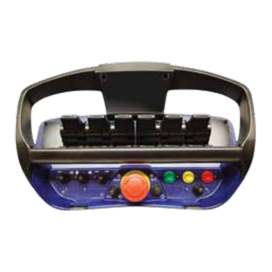
Document type Document number Page Service Manual S071 10 of 46 Getting started Portable Control Unit definition The illustrations below aims to delare all entities mentioned in this document. Cable port Micro-toggle Micro-LED Stop-button Power-LED On-button Activating the Portable Control Unit Insert battery or connect cable connector! 1. -
Page 11: Central Unit G2B Definition
Document type Document number Page Service Manual S071 11 of 46 Central Unit G2B definition The illustrations below aims to declare all entities mentioned in this document. R/M-Switch Status LEDs LED-display Cable / Programming port Terminal connectors Activating the Central Unit The Central Unit can be activated in two modes via the R/M switch;... -
Page 12: Central Unit G3B Definition
Document type Document number Page Service Manual S071 12 of 46 Central Unit G3B definition The illustrations below aims to declare all entities mentioned in this document. Cable A Cable C LED-display Cable B Activating the Central Unit G3B The Central Unit G3B is supplied thru Cable A and requires external power switching, see chapter 5.8 for further info. -
Page 13: Cable Or Radio Communication
Document type Document number Page Service Manual S071 13 of 46 Cable or radio communication Cable communication has higher priority than radio communication, if a cable link is present between the PCU and Central Unit this will be detected by the system, disabling radio communica- tion. Cable connection schematics Standard 10m cable connector Cable connection Pin no. Wire color Brown White Blue Black Grey Portable Control Unit Pin assignments Central Unit G2B/G3B Pin Assignments 5- pole male 5- pole female... -
Page 14: Inputs & Outputs
Document type Document number Page Service Manual S071 14 of 46 Inputs & Outputs Analogue functions The analogue inputs available for each platform (MAXI Linear, MAXI Joystick, MINI Linear and MINI Joy stick) are by default assigned an analogue output on the Central Unit, below figures declares the standard assignments. PCU MAXI Linear standard assignments PCU MAXI Joystick standard assignments... - Page 15 Document type Document number Page Service Manual S071 15 of 46 PCU MINI Linear standard assignments PCU MINI Joystick standard assignments...
-
Page 16: Portable Control Unit Maxi Digital Inputs
Document type Document number Page Service Manual S071 16 of 46 Portable Control Unit MAXI digital inputs The digital inputs available are NOT all by default assigned an digital output on the Central Unit, below figures only declares digital input access. 1-12 1-12 1-12 1-12 Terminal 1 Terminal 2 Type Colour Type Colour code Pin no. code Pin no. Common (GND) Black Common (GND) Black Digital input 33... -
Page 17: Portable Control Unit Mini Digital Inputs
Document type Document number Page Service Manual S071 17 of 46 Portable Control Unit MINI digital inputs The digital inputs available are NOT all by default assigned an digital output on the Central Unit, below figures only declares digital input access. 1-12 1-12 Terminal 1 Terminal 2 Type Colour Type Colour code Pin no. code Pin no. Common (GND) Black Common (GND) Black Digital input 33 Pink... -
Page 18: Digital Functions
Document type Document number Page Service Manual S071 18 of 46 Digital functions The digital functions utilized varies depending on system configuration, up to 20 digital functions can be implemented thru left- and/or right switch panels with programmable assignments to up to 14 digital outputs. In excess the On-button may also be assigned a digital output. Below shows PCU platforms standard digital inputs and default Central Unit output assignment On-button PCU MINI Standard assignment... -
Page 19: Terminal Schematics For Current Controlled Central Unit G2B
Document type Document number Page Service Manual S071 19 of 46 Terminal schematics for current controlled Central Unit G2B The drawing below declares access points for each available input and output both from the inside terminal (above) and the standard cable kits (below). Standard cable wire number/marking is also declared. -
Page 20: Terminal Schematics For Voltage Controlled Central Unit G2B
Document type Document number Page Service Manual S071 20 of 46 Terminal schematics for voltage controlled Central Unit G2B The drawing below declares access points for each available input and output both from the inside terminal (above) and the standard cable kits (below). Standard cable wire number/marking is also declared. -
Page 21: Terminal Schematics For Central Unit G2B Can Interface
Document type Document number Page Service Manual S071 21 of 46 Terminal schematics for Central Unit G2B CAN interface The Central Unit is equipped with terminal connections for CAN. The drawing below declares the access points both from the inside terminals (above) and the standard cable kit (below). 1= CAN H 2= CAN L 3= GND... -
Page 22: Connection Schematics For Central Unit G3B
Document type Document number Page Service Manual S071 22 of 46 Connection schematics for Central Unit G3B The Central Unit G3B is equipped with either 2 or 3 circular M12 5-pole connectors (check item no). The drawing below declares Pin-assignments for both versions of the Central Unit G3B Cable A (3 meters) Connection Pin no. -
Page 23: Central Unit Status And Operational Indications
Document type Document number Page Service Manual S071 23 of 46 Operational indications Central Unit status and operational indications The Central Unit G2B is equipped with 2 individual positions where status and operational indications can be read, the external LEDs STATUS and DV provides basic limited information whilst the LED display provides more detailed information, the Central Unit G3B only have the LED-display as shown below. Position 4: Status LEDs Position 5: LED-display External LEDs (on Central Unit G2B only!) LED STATUS... -
Page 24: Central Unit Led-Display
Document type Document number Page Service Manual S071 24 of 46 Central Unit LED-display Below table shows the variety of status indications available for both the Central Unit G2B and G3B: LED Display Meaning Off, deactivated Standby mode, no communication link with PCU Standby mode, communication link with PCU Communication link via cable, ID-code approved Communication link via cable, ID-code not approved Communication link via radio, frequency hopping Communication link via radio, frequency locked on channel 1 Communication link via radio, frequency locked on channel 2 Communication link via radio, frequency locked on channel 3... -
Page 25: Portable Control Unit Status Indications
Document type Document number Page Service Manual S071 25 of 46 Portable Control Unit status indications The Portable Control Unit uses 2 LEDs to indicate operational status, the Portable Control Unit is also equipped with an internal buzzer that emits sounds and alarms when required. Micro-LED Power-LED Typical status indications involving the Micro- and Power-LED are declared below: Power-LED Meaning Off, Portable Control Unit is deactivated... -
Page 26: Error Code Indications
Document type Document number Page Service Manual S071 26 of 46 Error code indications General description Both the Portable Control Unit and the Central Unit are embedded with constant fault monitoring, any errors noticed by the system will result in interruption of all operational commands. Central Unit Error codes All of the Central Units outputs are fault monitored for short circuits and/or overloads, in the event of an error being detected the Central Unit will alert that an error has occurred via the external LED Status and indicate the appropriate error code via the LED-display, the Central Unit will then reset to operational mode if possible. - Page 27 Document type Document number Page Service Manual S071 27 of 46 The LED-display Error codes are displayed in up to 3 sequences, this allows the Central Unit to declare exactly which output that is related to the error (where applicable). First sequence: Letters E:r is presented declaring an error code Second sequence: Type of error code Third sequence: Additional information (where applicable) In example: (Repeated 3 times)
- Page 28 Document type Document number Page Service Manual S071 28 of 46 7.2.1 Error codes (continued) Description 0utputs system Short circuit; Digital output (1-14) short circuited System will self reset. Digital output or overloaded (Could be any of the Check digital output connections. available 14 outputs) Remove terminal connector and reset system.
-
Page 29: Portable Control Unit Error Codes
Document type Document number Page Service Manual S071 29 of 46 7.2.1 Error codes (continued) ID programming ID-code and/or parameter settings System will self reset. failure not accepted. Verify ID-programming procedure. Reset application program. Program Programmable logic parameter error System will self reset. failure Reset application program. -
Page 30: Radio
Document type Document number Page Service Manual S071 30 of 46 Radio General description Radio is used as a bus link for data packages between the transmitter (Portable Control Unit) and receiver (Central Unit), the radio continuously transmits the positions of the analogue and digital inputs available on the Portable Control Unit to the Central Unit for further processing. The digitalized data transfer protocol uses a high security level for verification of each data pack- age, no loss of individual functions due to radio interferences can occur. -
Page 31: Diagnostics Mode
Document type Document number Page Service Manual S071 31 of 46 Diagnostics mode General description A diagnostics mode has been made available as to diagnose and manage the system, the LED- display is required to be monitored during diagnostics and will allow operator to read out recently occurred error codes, output characteristics and program information in order to diagnose the system. Activating diagnostics mode Note that the LED-display is required to be monitored during diagnostics mode. Do as follows: 1. - Page 32 Document type Document number Page Service Manual S071 32 of 46 Table / diagnosics data Position / LED Indication Meaning D:i - 0:0 Default position D:i - 0:1 Analogue output status D:i - 0:2 Digital output status D:i - 0:3 Digital Input status D:i - 0:4 Error code Log...
- Page 33 Document type Document number Page Service Manual S071 33 of 46 9.3.2 Position 2 - Digital output status Press On-button two times from position D:i – 0:0 D:i – 0:2 is displayed for 1 second, the LED-display will then toggle all Central Unit digital outputs and present current value (High or Low) O:n – 0:1 - 0:1 or 0:0 (High/Low) O:n –...
- Page 34 Document type Document number Page Service Manual S071 34 of 46 9.3.5 Position 5 - Program save Press On-button five times from position D:i – 0:0 D:i – 0:5 is displayed Press and hold Micro-toggle in LEFT position for 3 seconds C:o – F:A is displayed Release and press Micro-toggle once more to LEFT position to confirm and store the current set- tings Saves the current settings for DIRECTION and SPEEDS (START, STOPP, MICRO, RAMP) and DV- delay time as back-up for eventual future program load, see below chapter “program load”.
-
Page 35: 10 Online Programming Mode
35 of 46 10 Online Programming mode 10.1 General description The Scanreco RC 400 offers considerable possibilities for system constructors of hydraulically driven mobile cranes and machines. The program in the control system is very comprehensive, flexible and has many adaptation possibilities for specific applications. The control system offers simple programming of a number of functions which can easily be turned on or off or altered dur- ing operation. -
Page 36: Activating Online Programming Mode
Document type Document number Page Service Manual S071 36 of 46 10.2 Activating online programming mode The Central Units LED-display or Portable Control Units acoustic step signalling is required to be monitored during programming mode, check the table (10.3) for the indications given. Do as follows: 1. Remove the battery pack. Connect the cable between the Portable Control Unit and the Central Unit and test run the system. - Page 37 Document type Document number Page Service Manual S071 37 of 46 10.3 Table / Programming options Position via PCU Acoustic signal Meaning CU LED Indication (L=Long, S=Short) P:O - 0:0 Start / Default position P:O - 0:1 Direction P:O - 0:2 Start value SET1 P:O - 0:3 Stop value SET1...
- Page 38 Document type Document number Page Service Manual S071 38 of 46 10.3.4 Position 04 - Micro speed SET1 For individual adjustment of 1st step micro speed Available values: Values ranging from 1-100 When activating a lever/joystick the LED-display will indicate which output that is active and its corresponding 1st step micros speed.
- Page 39 Document type Document number Page Service Manual S071 39 of 46 10.3.10 Position 10 - Start ramp SET2 For individual adjustment of start ramp Available values: Values ranging from 0-100 (0 = No ramp delay, 1-50 = x100 ms delay/step) When activating a lever/joystick the LED-display will indicate which output that is active and its corresponding start ramp speed.
-
Page 40: 11 Portable Control Unit Self Test Mode
Document type Document number Page Service Manual S071 40 of 46 11 Portable Control Unit self test mode 11.1 General description To simplify service and faultfinding, the portable control unit can be put into internal self test mode. This means that the service man can easily control the Portable Control unit’s switches and manoeuvre levers, without the need to open the Portable Control Unit. When each switch or manoeuvre lever is activated / manoeuvred the Portable Control Unit gives a “beep - signal” to confirm that the function is working. -
Page 41: 12 Id-Code Programming
Document type Document number Page Service Manual S071 41 of 46 12 ID-code programming 12.1 General description The unique ID-code required for radio communication is programmed between the Portable Control Unit and Central Unit The Central Unit may store the ID-code of maximum one (1) Portable Control Unit, if another Portable Control Unit is required to operate the Central Unit via radio the ID-code procedure is required to be done. -
Page 42: 13 G2B Standard Cable Kits
Document type Document number Page Service Manual S071 42 of 46 13 G2B Standard Cable Kits 13.1 General description Various standard cable kits exist to suit certain system configurations and valves/coils. Typically two sets of cable kits are required, one for power supply and digital functions and one for analogue functions, see below illustration. 1 = Left side; “Supply Cable kit” for power supply and digital functions. 2 = Right side; “Valve Cable kit” for analouge functions. -
Page 43: Standard Supply Cable Kits
Document type Document number Page Service Manual S071 43 of 46 13.2 Standard Supply cable kits For connection of power supply input, DV-output, Digital functions and CANBUS. Central Unit type: 2010 2011 3010 3011 Girder/cable alignment: +/- Power supply See chapter 5.5 - 5.6 for assignments DV - Dump Valve output Hirchmann GDM3009 EX1 - Digital functions See chapter 5.5 - 5.6 for... -
Page 44: Standard Valve Cable Kits For Sauer-Danfoss Pvg-32
Document type Document number Page Service Manual S071 44 of 46 13.3 Standard valve cable kits for Sauer-Danfoss PVG-32 For connection of analogue functions for Sauer-Danfoss PVG-32 module Central Unit type: 2010 2011 Girder/cable alignment: CONNECTOR: AMP-JPT 4-pol WIRE: 1 = MODULE SUPPLY 2 = REGULATED SUPPLY 3 = GND CONNECTOR:... -
Page 45: Standard Valve Cable Kits For Hawe
Document type Document number Page Service Manual S071 45 of 46 13.3 Standard valve cable kits for HAWE For connection of analogue functions for HAWE module Central Unit type: 3010 3011 Girder/cable alignment: CONNECTOR: Hirchmann GDM3009 WIRE: 1 = PWM+ A 2 = PWM - 3 = PWM+ B Cable specification:... -
Page 46: Service Manual S071 C 2 Of
Document type Document number Page Service Manual S071 46 of 46 13.3 Standard valve cable kits for PWM solenoids For connection of analogue functions for PWM solenoids Central Unit type: 3010 3011 Girder/cable alignment: CONNECTOR: AMP-JPT 2-pol WIRE: 1 = PWM+ 2 = PWM- CONNECTOR: Hirchmann GDM3009...
Need help?
Do you have a question about the RC400 G2B and is the answer not in the manual?
Questions and answers
Hi, I have 2 x scanreco RC400 remote units, i can program both controllers to work with either receiver, but i am unable to get either controller to work when in remote only (cable disconnected) both units function as they should when plugged in with the cable. Any help would be greatly appreciated.
To troubleshoot the Scanreco RC400 G2B remote units to function in remote-only mode:
1. Ensure the Portable Control Unit is connected via cable and power is supplied.
2. Turn on the unit and check that the Power-LED remains lit during start-up.
3. The Power-LED should stay on until the last 5 beeps are heard. If the unit deactivates before this, it indicates an internal malfunction.
4. Verify correct connection of the standard cable kits:
- Left side: "Supply Cable Kit" for power supply and digital functions.
- Right side: "Valve Cable Kit" for analogue functions.
If the unit still does not function remotely, it may require inspection or replacement due to internal failure.
This answer is automatically generated