Table of Contents
Advertisement
Quick Links
Advertisement
Table of Contents
Troubleshooting

Related Manuals for Vxl Itona LQ Series


Summary of Contents for Vxl Itona LQ Series
- Page 1 Itona LQ, LQ+ Series Hardware User Guide...
- Page 2 Copyright © 2004-2014 VXL Instruments Limited. All Rights Reserved Information in this document is subject to change without notice and does not represent a commitment on the part of the manufacturer. No part of this guide may be reproduced or transmitted in any form or means, electronic or mechanical, including photocopying and recording, for any purpose, without the express written permission of the manufacturer.
-
Page 3: Product Safety
Improper connecting or mounting of the product could result in product failure or damage. Refer to the LQ Series Installation Guide for more information about setting up the thin client. VXL Technical Support To access VXL hardware and software documentation, visit: http://www.vxl.net//Independent/product-manuals.aspx For online support or reporting a problem, visit:... - Page 4 For more details about Product Warranty, visit: http://www.vxl.net/Support/Product-Warranty-Terms.aspx...
-
Page 5: Energy Star Compliant Product
ENERGY STAR Compliant Product ENERGY STAR is a joint program of the U.S. Environmental Protection Agency and the U.S. Department of Energy helping us all save money and protect the environment through energy efficient products practices. Please visit http://www.energystar.gov for detail information on the ENERGY STAR joint program. -
Page 6: Regulatory Certifications
Regulatory Certifications... -
Page 7: Table Of Contents
Table of Contents Federal Communication Commission (FCC) Statement Battery Information Product Safety VXL Technical Support ENERGY STAR Compliant Product Regulatory Certifications 1 Introduction Features Optional Features About the User Guide Abbreviations and Acronyms User Manual Organization 2 Installation Unpacking the Unit... - Page 8 Recommended Orientation Replacing the Battery General Troubleshooting Reporting a Problem Appendix...
-
Page 9: Introduction
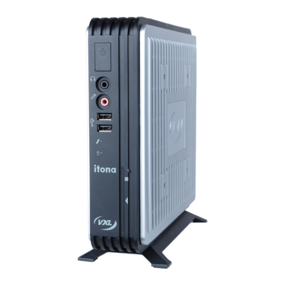
Introduction Thin Clients are terminal devices that connect to multi-user application servers operating under Citrix XenDesktop, XenApp, VMware View connection server and Windows 2003/2008 terminal servers. This guide covers installation procedure and hardware details of Itona LQ/LQ+ series. 1. Power Button. 2. -
Page 10: Features
This thin client communicates with application servers via the ICA protocol developed by Citrix Systems Inc., Remote Desktop Protocol from Microsoft and a host of other popular connectivity protocols. Features This thin client is equipped with a Gigabit Ethernet port that provides instant connection to multi-user Windows NT application servers. - Page 11 Introduction This chapter contains an overview of the product, information about this guide and abbreviations used in this guide. Installation This chapter contains the procedure to set up the hardware. Specifications This chapter contains hardware, mechanical, electrical, interface and operating environment specifications Troubleshooting This chapter contains solutions to problems that you may encounter while using the...
-
Page 12: Installation
Installation Perform the following steps to successfully install and set up LQ/LQ+ series. 1. Unpack the unit. 2. Prepare to connect. 3. Connect the secure USB shell devices. 4. Install the pedestal. 5. Fix the external antenna (Optional). 6. Install the VESA Dock (Optional). 7. -
Page 13: Accessing The Secure Usb Shell
Accessing the Secure USB Shell Note: No user serviceable parts inside the thin client. Please contact a VXL authorized service professional to remove the casing and access the secure USB shell. Warning: Hot temperatures inside the thin client. Switch off and unplug the device, leave it idle for at least 30 minutes before removing the top and the bottom strips of the thin client. - Page 14 Caution: Pull out the tabs gently out of its groove. 4. Break open the secure shell USB wire seal in the front bezel using a screwdriver as shown in the following figure. Figure 2-3: Opening the Secure Shell USB Wire Seal Note: A gentle clockwise rotation of the screwdriver will break the wire seal.
-
Page 15: Installing The Pedestal
Installing the Pedestal Fix the pedestal to the bottom of the thin client before you place it on a flat surface. Do not fix the pedestal if you are mounting this thin client using the VESA bracket. For more information about mounting using a VESA bracket, see section ‘Mounting using VESA Dock’. -
Page 16: Fixing The External Antenna
2. Press the tab and then slide the stand outwards and lift the pedestal off the thin client. Fixing the External Antenna An external antenna is used to receive wireless LAN signals. To fix an external antenna: 1. Connect the antenna to the WLAN port in the back panel of the thin client. New Image to be inserted Figure 2-6: Fixing the External Antenna 2. - Page 17 Figure 2-8: Mounting the Thin Client using a VESA Use a screwdriver to fasten the captive screw at the top of the dock. Following are the various VESA Dock mounting options: Figure 2-9 Wall Mounted Client Figure 2-10: Wall Mounted Client and Monitor Draft Installation...
- Page 18 Figure 2-11: Under the Counter Left Figure 2-12: Behind the Monitor Draft Installation...
-
Page 19: Mounting Using The Pedestal
Mounting using the Pedestal You can mount the thin client under the counter top using the pedestal. To mount the thin client under the counter top: Figure 2-13: Mounting under the Counter Top 1. Place the pedestal under the counter top. 2. -
Page 20: Connecting The Cables And Power Supply
4. Power Cord Anchor 5 Mini PCIe Wireless 6. Two USB 2.0 Ports 7. Two USB 3.0 Ports 8. HDMI Port 9. Display Port 10. Ethernet Port 11. DC Power In 12. Pedestal Figure 2-15: Itona LQ Series Rear View Draft Installation... - Page 21 1. Graphics Card (Optional) 2. Serial Port 3. Power Cord Anchor 4. Mini PCIe Wireless LAN (Optional) 5. Two USB 2.0 Ports 6. Two USB 3.0 Ports 7. HDMI Port 8. Display Port 9. Ethernet Port 10. DC Power In 11.
- Page 22 Connectors Connector Symbol HDMI Port USB 2.0 Port USB 3.0 Port Audio Out Port Mic Port Display Port COM Port VGA Port Display Port Ethernet Port (RJ45) Mini PCIe Wireless LAN Antenna Table 1: Connector Symbols Note: Before connecting any cable, ensure that the power cable is unplugged from the unit.
-
Page 23: Using The Kensington Lock
Caution: Ensure that the COM port is adequately fastened with the captive screws provided along with the cables. Using the Kensington Lock Kensington Lock secures your thin client from unauthorized removal and theft. There are two Kensington Lock slots provided at the top and bottom strips of this thin client. Purchase a compatible Kensington lock to use with these slots. - Page 24 1. Connect one end of an Ethernet cable to the Ethernet Port in the client. 2. Connect the other end to a LAN hub as shown in Figure 2-24. Figure 2-19: LAN Connection through TCP/IP 3. Press the power button to switch on the thin client. The front panel LED lights up and you will hear a beep.
-
Page 25: Specifications
Specifications Hardware* Processor LQ/LQ+ AMD Kabini A4-5000 Quad Core 1.5 GHz SoC Flash SSD 22 Pin Up to 8 GB DDR3 1600/1333 MHz SO- DIMM Graphic Processor Built-in Radeon HD 8330 graphics processor Maximum Display resolution Display Port: 2560 x 1600, @32bpp HDMI: 1920 x 1200 @32bpp VGA: 1920 x 1200 @32bpp Front Panel... -
Page 26: Mechanical
Internal Features Mono speaker 1 x PCIe slot 1 x mPCIe slot 1 x PCIe Riser Card slot Optional Features 1 x Parallel Port Internal USB WLAN through secure USB compartment Mini PCIe WLAN Card with external antenna Display Port to DVI, Display Port to HDMI and Display Port to VGA converter cables VESA Dock (100 x 100 or 75 x 75 mm mounting holes) Mechanical... - Page 27 Efficiency >85% *Specifications may vary based on LQ or LQ+ series. Please check the relevant product datasheet for more information. Draft Specifications...
-
Page 28: Troubleshooting
We recommend that you place or install this thin client vertically; this allows natural heat dissipation. We do not recommend placing the device horizontally. Do not block the air vents on the sides. Replacing the Battery Contact a VXL authorized professional technician to replace the battery in your thin client. Draft Troubleshooting... -
Page 29: General Troubleshooting
PS/2 port. switched on. Reporting a Problem You can report a specific problem to the VXL after-sales service. To report a problem or check the status of your issue go to http://www.vxl.net/Support/Online-support.aspx. Note: For more information about reporting a problem and checking its status, refer to the Itona LQ/LQ+ series Installation Guide document shipped with your product. -
Page 30: Appendix
Appendix Connectors The following section provides pin details for various connectors on the rear panel of the client. COM Port 9-pin D-type male connector, RS232C compatible, operating at 115.2 K baud maximum. Signal Description Data Carrier Detect Receive Data Transmit Data Data Terminal Ready Signal Ground Data Set Ready... - Page 31 Printer Port (Parallel) 25-pin D-type female connector. ECP/EPP compatible. Signal STROBE DATA 0-7 ACKNOWLEDGE BUSY PAPER END ERROR 18-25 GROUND Appendix...
-
Page 32: Display Port
Display Port 20 pin port with 1.62, 2.7, or 5.4 Gbit/s data rate per lane; 1, 2, or 4 lanes; 1 Mbit/s or 720 Mbit/s for the auxiliary channel. Signal Signal Lane 0 (positive) Ground Ground Lane 3 (negative) Lane 0 (negative) Connected to Ground Lane 1 (positive) Connected to Ground... - Page 33 DVI-I Port Pin C1 to C5 carry the analogue signal.24+5 pin DVI Connector. Signal Signal Signal TMDS Data 2- TMDS Data 1/3 TMDS Data 5+ Shield TMDS Data 2+ TMDS Data 3- TMDS Clock Shield TMDS Data 2/4 TMDS Data 3+ TMDS Clock + Shield TMDS Data 4-...
- Page 34 Gigabit Ethernet LAN Port RJ-45 modular 8-pin jack. 10/100/1000 Mbps. Signal TxD+ TxD- RxD+ RxD- PS/2 Mouse/Keyboard Port Mouse/Keyboard connector Signal Signal Mouse / KBD data Mouse / KBD Clock Audio Port Line Out/Mic ports. Standard audio jacks. Appendix...
- Page 35 USB Port 2.0/USB Port 3.0 4-pin series-A receptacle. 6 ports. Signal HDMI Port Signal Signal TMDS Data2+ TMDS Clock Shield TMDS Data2 Shield TMDS Clock− TMDS Data2− TMDS Data1+ Reserved (HDMI 1.0–1.3c), HEC Data (Optional, HDMI 1.4+ with Ethernet) TMDS Data1 Shield SCL (I²C Serial Clock for DDC) TMDS Data1−...
- Page 36 TMDS Clock+ Hot Plug detect (all versions) and HEC Data+ (optional, HDMI 1.4+ with Ethernet) Appendix...
Need help?
Do you have a question about the Itona LQ Series and is the answer not in the manual?
Questions and answers