
Related Manuals for Bull R424-E2


Summary of Contents for Bull R424-E2
- Page 1 R424-E2/R424-INF-E2 R424-F2/R424-INF-F2 Installation and User's Guide REFERENCE 86 A1 61FE 01...
- Page 3 R424-E2/R424-INF-E2 R424-F2/R424-INF-F2 Installation and User's Guide Hardware February 2011 BULL CEDOC 357 AVENUE PATTON B.P.20845 49008 ANGERS CEDEX 01 FRANCE REFERENCE 86 A1 61FE 01...
- Page 4 Phoenix® is a registered trademark of Phoenix Technologies. The information in this document is subject to change without notice. Bull will not be liable for errors contained herein, or for incidental or consequential damages in connection with the use of this material.
-
Page 5: About This Manual
E2 or the bullx R424-F2/R424-INF-F2. Installation and maintenance should be performed by experienced technicians only. The bullx R424-E2/R424-INF-E2 and R424-F2/R424-INF-F2 are 2U Bi-Twin (four serverboards in a 2U chassis) rackmount server chassis and two R424-E2/ R424-INF-E2 or R424-F2/R424-INF-F2 serverboards. The R424-E2/R424-INF-E2 and R424-F2/R424-INF-F2 serverboards support Intel® 5500 Series Processor (Nehalem) and Intel®... - Page 6 Chapter 6: Advanced Chassis Setup Refer to Chapter 6 for detailed information on the R424-E2/R424-INF-E2 and R424-F2/R424-INF-F2 1U rackmount server chassis. You should follow the procedures given in this chapter when installing, removing or reconfi guring SAS/ SATA or peripheral drives and when replacing system power supply units and cooling fans.
-
Page 7: Table Of Contents
Table of Contents Table of Contents Chapter 1. Introduction Overview ..................... 1-1 Serverboard Features ................1-2 CPU....................... 1-2 Memory ....................1-2 Onboard SAS (R424-F2/R424-INF-F2 only) ......... 1-2 Chipset ....................1-2 Expansion Slot ..................1-2 BIOS...................... 1-3 PC health Monitoring ................1-3 ACPI Features .................. - Page 8 R424-E2/R424-INF-E2 and R424-F2/R424-INF-F2 Installation and User's Guide Installing the System into a Rack .............. 2-4 Identifying the Sections of the Rack Rails ..........2-4 Locking Tabs ..................2-5 Releasing the Inner Rail ............... 2-5 Releasing Inner Rail from the Outer Rails ........2-5 Installing The Inner Rails on the Chassis ..........
- Page 9 Add-on Card/Expansion Slot Setup ............ 5-15 Installing the Riser Card ..............5-16 Installing Add-on Cards ............... 5-17 Serverboard Details .................. 5-18 R424-E2 Quick Reference ..............5-21 R424-F2 Quick Reference ..............5-23 Serverboard Features ................. 5-24 CPU ....................5-24 Memory ................... 5-24 Chipset ....................
- Page 10 Chassis view for R424-E2 and R424-INF-E2 ........6-2 Chassis view for R424-F2 and R424-INF-F2 ........6-2 Installing and Removing Hard Drives on R424-E2 and R424-INF-E2 ..6-3 Removing Hard Drive Trays from the Chassis ......... 6-4 Installing a Drive into the Hard Drive Tray ........6-6 Installing and Removing Hard Drives on R424-F2 and R424-INF-F2 ..
- Page 11 Table of Contents Chapter 7. Troubleshooting Before Power On .................. 7-1 No Power ....................7-1 No Video ....................7-2 Losing the System’s Setup Confi guration ..........7-2 Memory Errors ..................7-2 Chapter 8. BIOS Introduction ....................8-1 Main Setup ....................8-2 Advanced Setup Confi...
- Page 12 R424-E2/R424-INF-E2 and R424-F2/R424-INF-F2 Installation and User's Guide...
-
Page 13: Chapter 1. Introduction
2U chassis and four (bi-twin) R424-E2/R424-INF-E2 and R424-F2/R424-INF-F2 serverboards. Please refer to our web site for information on operating systems that have been certifi ed for use with the bullx R424-E2/R424- INF-E2 and R424-F2/R424-INF-F2. In addition to the serverboard and chassis, various hardware components may have been included with the bullx R424-E2/R424-INF-E2 and R424-F2/R424-INF-F2, as listed below. -
Page 14: Serverboard Features
R424-E2/R424-INF-E2 and R424-F2/R424-INF-F2 Installation and User's Guide Serverboard Features At the heart of the bullx R424-E2/R424-INF-E2 and R424-F2/R424-INF-F2 lies four R424-E2/R424-INF-E2 or R424-F2/R424-INF-F2 dual processor serverboards, which are based on Intel's S5520 chipset (Tylersburg IOH-36D). Below are the main features of the bullx R424-E2/R424-INF-E2 and R424-F2/R424-INF-F2 ser- verboards. -
Page 15: Bios
Chapter 1: Introduction BIOS • 32 Mb AMI SPI Flash ROM. • ACPI 1.0/2.0/3.0, Plug and Play (PnP), and USB Keyboard support. PC health Monitoring Onboard voltage monitors for CPU1 VCore, CPU2 VCore, +5Vin, 1 2Vcc • (V), VP1 DIMM, VP2 DIMM, +3.3Vcc (V), and Battery Voltage. •... -
Page 16: Graphics Controller
R424-E2/R424-INF-E2 and R424-F2/R424-INF-F2 Installation and User's Guide • Dual Intel 82574 Dual-LAN Gigabit Ethernet Controllers support dual Giga- bit LAN ports. • Onboard PHY Chip supports IPMI dedicated LAN. • One COM port. • Infi niBand Connector. • Up to four USB 2.0 (Universal Serial Bus) connections (2 Rear USB Ports and 1 Type A Header w/2 USB connections supported). - Page 17 Chapter 1: Introduction Figure 1-1. System Block Diagram Note: This is a general block diagram. See the Motherboard Features pages for details on the features of each motherboard.
-
Page 18: Chassis Components
6 x SAS2 LSI 2108.. Fans • The bullx R424-E2 and R424-F2 chassis accept four system fans. System fans for the chassis are powered from the motherboards or the HDD back- plane. The two fans on each side are controlled by two motherboards, so that when one of the motherboard nodes is removed, the second mother- board will continue to control both fans. - Page 19 Chapter 1: Introduction Air Shroud • The bullx R424-E2 and R424-F2 chassis require mylar air shrouds for each node to direct the airfl ow where cooling is needed.
- Page 20 R424-E2/R424-INF-E2 and R424-F2/R424-INF-F2 Installation and User's Guide Notes...
-
Page 21: Chapter 2. Server Installation
fi le a damage claim with the carrier who delivered it. Decide on a suitable location for the rack unit that will hold the bullx R424-E2/ R424-INF-E2 or R424-F2/R424-INF-F2. It should be situated in a clean, dust-free area that is well ventilated. -
Page 22: Rack Precautions
R424-E2/R424-INF-E2 and R424-F2/R424-INF-F2 Installation and User's Guide • This product is for installation only in a Restricted Access Location (dedicated equipment rooms, service closets and the like). • This product is not suitable for use with visual display work place devices according to §2 of the the German Ordinance for Work with Visual Display... -
Page 23: Rack Mounting Considerations
Chapter 2: Server Installation • Always keep the rack's front door and all panels and components on the serv- ers closed when not servicing to maintain proper cooling. • Make sure all power and data cables are properly connected and not blocking the chassis airfl... -
Page 24: Installing The System Into A Rack
R424-E2/R424-INF-E2 and R424-F2/R424-INF-F2 Installation and User's Guide Installing the System into a Rack This section provides information on installing the chassis into a rack unit with the rails provided. There are a variety of rack units on the market, which may mean that the assembly procedure will differ slightly from the instructions provided. -
Page 25: Locking Tabs
Chapter 2: Server Installation Locking Tabs Each inner rail has a locking tab. This tab locks the chassis into place when installed and pushed fully into the rack. These tabs also lock the chassis in place when fully extended from the rack. This prevents the server from coming completely out of the rack when when the chassis is pulled out for servicing. -
Page 26: Installing The Inner Rails On The Chassis
R424-E2/R424-INF-E2 and R424-F2/R424-INF-F2 Installation and User's Guide Installing The Inner Rails on the Chassis Installing the Inner Rails Confi rm that the left and right inner rails have been correctly identifi ed. Place the inner rail fi rmly against the side of the chassis, aligning the hooks on the side of the chassis with the holes in the inner rail. -
Page 27: Installing The Outer Rails On The Rack
Chapter 2: Server Installation Figure 2-4. Inner Rails Installed on the Chassis Installing The Outer Rails on the Rack Installing the Outer Rails Press upward on the locking tab at the rear end of the middle rail. Push the middle rail back into the outer rail. Hang the hooks of the front of the outer rail onto the slots on the front of the rack. -
Page 28: Standard Chassis Installation
R424-E2/R424-INF-E2 and R424-F2/R424-INF-F2 Installation and User's Guide Figure 2-5. Installing the Server into a Rack Figure 2-5. Extending and Releasing the Outer Rails Standard Chassis Installation Installing the Chassis into a Rack Confi rm that the inner rails are properly installed on the chassis. - Page 29 Chapter 2: Server Installation Figure 2-6. Installing into a rack...
-
Page 30: Optional Quick Installation Method
R424-E2/R424-INF-E2 and R424-F2/R424-INF-F2 Installation and User's Guide Optional Quick Installation Method The following quick installation method may be used to install the chassis onto a rack. Installing the Chassis into a Rack Install the whole rail assembly onto the rack. -
Page 31: Checking The Serverboard Setup
Chapter 2: Server Installation Checking the Serverboard Setup After you install the bullx R424-E2/R424-INF-E2 or R424-F2/R424-INF-F2 in the rack, you will need to open the top cover to make sure the serverboard is properly installed and all the connections have been made. -
Page 32: Preparing To Power On
R424-E2/R424-INF-E2 and R424-F2/R424-INF-F2 Installation and User's Guide Preparing to Power On Next, you should check to make sure the peripheral drives and the SATA drives and SATA backplane have been properly installed and all connections have been made. Checking the SATA drives or SAS drives (only on R424-F2) All drives are accessable from the front of the server. -
Page 33: Chassis Cover
Chassis Cover Figure 2-7. Removing the Chassis Cover Before operating the R424-E2 or R424-F2 chassis for the fi rst time, it is important to remove the protective fi lm covering the top of the chassis, in order to allow for proper ventilation and cooling. - Page 34 R424-E2/R424-INF-E2 and R424-F2/R424-INF-F2 Installation and User's Guide Warning: Except for short periods of time, do NOT operate the server without the cover in place. The chassis cover must be in place to allow proper air- fl ow and prevent overheating.
-
Page 35: Chapter 3. System Interface
There are several LEDs on the control panel and on the drive carriers to keep you constantly informed of the overall status of the system. R424-E2 and R424-F2 models include four control panels on the handles of the chassis which control each of the systems. -
Page 36: Control Panel Buttons
R424-E2/R424-INF-E2 and R424-F2/R424-INF-F2 Installation and User's Guide Control Panel Buttons • Power: The main power button on each of the four control panels is used to apply or remove power from the power supply to each of the four systems in the chassis. -
Page 37: Drive Carrier Leds
Chapter 3: System Interface • NIC: Indicates network activity on either LAN1 or LAN2 when fl ashing. Drive Carrier LEDS The R424-E2 and R424-F2 chassis use SAS/SATA drives. SAS/SATA Drives Each SAS/SATA drive carrier has two LEDs. • Blue: Each Serial ATA drive carrier has a blue LED. When illuminated, this blue •... - Page 38 R424-E2/R424-INF-E2 and R424-F2/R424-INF-F2 Installation and User's Guide Notes...
-
Page 39: Chapter 4. System Safety
Chapter 4. System Safety Electrical Safety Precautions Basic electrical safety precautions should be followed to protect yourself from harm and the bullx R424-E2/R424-INF-E2 or R424-F2/R424-INF-F2 from damage: • Be aware of the locations of the power on/off switch on the chassis as well as the room's emergency power-off switch, disconnection switch or electrical outlet. -
Page 40: General Safety Precautions
Contact technical support for details and support. General Safety Precautions Follow these rules to ensure general safety: • Keep the area around the bullx R424-E2/R424-INF-E2 or R424-F2/R424-INF-F2 clean and free of clutter. • The bullx R424-E2/R424-INF-E2 and R424-F2/R424-INF-F2 weighs approxi- mately 40 lbs (~18.2 kg) when fully loaded. -
Page 41: Esd Precautions
Chapter 4: System Safety ESD Precautions Electrostatic discharge (ESD) is generated by two objects with different electrical charges coming into contact with each other. An electrical discharge is created to neutralize this difference, which can damage electronic com ponents and printed circuit boards. -
Page 42: Operating Precautions
R424-E2/R424-INF-E2 and R424-F2/R424-INF-F2 Installation and User's Guide Operating Precautions Care must be taken to assure that the chassis cover is in place when the bullx R424-E2/R424-INF-E2 or R424-F2/R424-INF-F2 is operating to assure proper cooling. Out of warranty damage to the system can occur if this practice is not strictly followed. -
Page 43: Chapter 5. Advanced Serverboard Setup
Chapter 5: Advanced Serverboard Setup Chapter 5. Advanced Serverboard Setup This chapter covers the steps required to install the bullx R424-E2/R424-INF-E2 or R424-F2/R424-INF-F2 serverboard into the chassis, connect the data and power cables and install add-on cards. All serverboard jumpers and connections are also described. -
Page 44: Installing The Serverboard
Permanent and Optional Standoffs Standoffs prevent short circuits by securing space between the serverboard and the chassis surface. The R424-E2 and R424-F2 chassis include permanent standoffs in locations used by the serverboards. These standoffs accept the rounded Phillips head screws included in the R424-E2 and R424-F2 accessories packaging. - Page 45 Chapter 5: Advanced Serverboard Setup Figure 5-2. Installing he Serverboard in the Serverboard Node Drawer Installing the Serverboard Review the documentation that came with your serverboard. Become familiar with component placement, requirements, precautions, and cable connec- tions. Pull the serverboard node drawer out of the back of the chassis. 2. Remove the add-on card brackets: 3a.
-
Page 46: Connecting Cables
R424-E2/R424-INF-E2 and R424-F2/R424-INF-F2 Installation and User's Guide Connect the cables between the serverboard, backplane, chassis, front panel, and power supply, as needed. Also, fans may be temporarily removed to al- low access to the backplane ports. Replace the add-on card bracket and secure the bracket with a screw. -
Page 47: Connecting The Control Panel
Chapter 5: Advanced Serverboard Setup Connecting the Control Panel JF1 contains header pins for various front control panel connectors. See Figure 5-3 for the pin locations of the various front control panel buttons and LED in- dicators. All JF1 wires have been bundled into a single ribbon cable to simplify this connection. -
Page 48: Control Panel Connectors/Io Ports
R424-E2/R424-INF-E2 and R424-F2/R424-INF-F2 Installation and User's Guide Control Panel Connectors/IO Ports The I/O ports are color coded in conformance with the PC 99 specifi cation. See the picture below for the colors and locations of the various I/O ports. -
Page 49: Installing Processor And Heat Sink
Chapter 5: Advanced Serverboard Setup Installing Processor and Heat Sink When handling the processor package, avoid placing direct pressure on the label area of the fan. Notes: Always connect the power cord last and always remove it before adding, removing or changing any hardware components. Make sure that you install the processor into the CPU socket before you install the CPU heatsink. - Page 50 R424-E2/R424-INF-E2 and R424-F2/R424-INF-F2 Installation and User's Guide 4. After removing the plastic cap, us- ing your thumb and the index fi nger , hold the CPU at the north and south center edges. 5. Align the CPU key, the semi-circle...
-
Page 51: Installing A Cpu Heatsink
Chapter 5: Advanced Serverboard Setup Installing a CPU Heatsink 1. Do not apply any thermal grease to the heatsink or the CPU die because the required amount has already been applied. Screw #1 Screw #2 2. Place the heatsink on top of the CPU so that the four mounting holes are aligned with those on the retention mechanism. -
Page 52: Removing The Heatsink
R424-E2/R424-INF-E2 and R424-F2/R424-INF-F2 Installation and User's Guide Removing the Heatsink Warning: We do not recommend that the CPU or the heatsink be removed. However, if you do need to remove the heatsink, please follow the instructions below to uninstall the heatsink and prevent damage to the CPU or other components. -
Page 53: Installing Memory
Chapter 5: Advanced Serverboard Setup Installing Memory CAUTION Exercise extreme care when installing or removing DIMM modules to prevent any possible damage. Also note that the memory is interleaved to improve performance (See step 1). Installing a DIMM Insert the desired number of DIMMs into the memory slots, starting with P1-DIMM 1A. -
Page 54: Memory Support
R424-E2/R424-INF-E2 and R424-F2/R424-INF-F2 Installation and User's Guide Memory Support The R424-E2/R424-INF-E2 and R424-F2/R424-INF-F2 support up to 96 GB Regis- tered ECC or 24 GB of Unbuffered ECC/Non-ECC DDR3 1333 MHz/1066 MHz/800 MHz in 12 DIMMs (with maximum of 8 GB of Registered ECC per DIMM slot). -
Page 55: Installing And Removing Dimms
Chapter 5: Advanced Serverboard Setup Possible System Memory Allocation & Availability System Device Size Physical Memory Available (4 GB Total System Memory) Firmware Hub fl ash memory (System BIOS) 1 MB 3.99 GB Local APIC 4 KB 3.99 GB Area Reserved for the chipset 2 MB 3.99 GB I/O APIC (4 Kbytes) -
Page 56: Installing And Replacing Adapter Cards
R424-E2/R424-INF-E2 and R424-F2/R424-INF-F2 Installation and User's Guide Installing and Replacing Adapter Cards Adapter cards provide hot-swappable functionality to the chassis. Figure 5-6. Adapter Card Installlation Removing the Adapter Card Remove the motherboard drawer from the chassis. Disconnect the wiring, connecting the adapter card to the motherboard if any is present. -
Page 57: Add-On Card/Expansion Slot Setup
Chapter 5: Advanced Serverboard Setup Add-on Card/Expansion Slot Setup The R424-E2 and R424-F2 chassis support one low-profi le expansion slot for each node, for a total of four slots in the chassis. To install a low-profi le PCI card, follow the instructions below. -
Page 58: Installing The Riser Card
R424-E2/R424-INF-E2 and R424-F2/R424-INF-F2 Installation and User's Guide Installing the Riser Card Disconnect the power supply and lay the chassis on a fl at surface. Pull the serverboard node drawer from the chassis. Remove the add-on card bracket. 3a. Remove the screw securing the add-on bracket to the back of the drawer. -
Page 59: Installing Add-On Cards
Chapter 5: Advanced Serverboard Setup Installing Add-on Cards Disconnect the power supply, lay the chassis on a fl at surface, and open the chassis cover. Pull out the serverboard node drawer from the chassis. Pull open the add-on card slot clip in the rear of the serverboard node drawer. Remove the PCI slot shield. -
Page 60: Serverboard Details
R424-E2/R424-INF-E2 and R424-F2/R424-INF-F2 Installation and User's Guide Serverboard Details Figure 5-10. bullx R424-E2 or R424-F2 serverboard image Model Variations R424-E2 R424-INF-E2 (QDR) R424-F2 R424-INF-F2 (QDR) IPMI 2.0 w/ KVM Over LAN Infi niBand Connection QDR IB Note: The drawings and pictures shown in this manual were based on the latest PCB Re- vision available at the time of publishing of the manual. - Page 61 Chapter 5: Advanced Serverboard Setup Figure 5-11. bullx R424-E2 or R424-F2 Layout umpers not indicated are for test purposes only. For more information on jumpers or components, refer to 'Jumper Settings' in this chapter. " " indicates the location of Pin 1.
- Page 62 R424-E2/R424-INF-E2 and R424-F2/R424-INF-F2 Installation and User's Guide Figure 5-12. bullx R424-E2 serverboard Quick Reference 5-20...
-
Page 63: R424-E2 Quick Reference
Chapter 5: Advanced Serverboard Setup R424-E2 Quick Reference Jumper Description Default Setting JBMC1 BMC Enable/Disable Pins 1-2 (Enabled) JBT1 CMOS Clear (See page 5-36) JPEN1 Normal Power Enable Pins 1-2 (Enabled) JPG1 VGA Enable/Disable Pins 1-2 (Enabled) JPL1 LAN1/2 Enable/Disable... - Page 64 R424-E2/R424-INF-E2 and R424-F2/R424-INF-F2 Installation and User's Guide Figure 5-13. bullx R424-F2 serverboard Quick Reference 5-22...
-
Page 65: R424-F2 Quick Reference
Chapter 5: Advanced Serverboard Setup R424-F2 Quick Reference Jumper Description Default Setting JBT1 CMOS Clear (See page 5-36) JPG1 VGA Enable/Disable Pins 1-2 (Enabled) JPL1/JPL2 LAN1/2 Enable/Disable Pins 1-2 (Enabled) JWD1 Watch Dog Enable/Disable/Reset Pins 1-2 (Reset) Connector Description COM1 COM1 Serial Port FAN 1 Fan Headers... -
Page 66: Serverboard Features
R424-E2/R424-INF-E2 and R424-F2/R424-INF-F2 Installation and User's Guide Serverboard Features • Two Intel® Xeon® 5500 Series processors (code-named Nehalem EP) or Intel® Xeon® 5600 Series processors (code-named Westmere EP) with each proces- sor supporting two full-width Intel QuickPath Interconnect (QPI) links with a total of up to 51.2 GT/s Data Transfer Rate supported (6.4 GT/s per direction) -
Page 67: Acpi Features
Chapter 5: Advanced Serverboard Setup • Power-up mode control for recovery from AC power loss • Auto-switching voltage regulator for CPU cores • System overheat/Fan Fail LED Indicator and control ACPI Features • Slow blinking LED for suspend state indicator •... -
Page 68: Back Panel Connector Pin Defi Nitions
R424-E2/R424-INF-E2 and R424-F2/R424-INF-F2 Installation and User's Guide Back Panel Connector Pin Defi nitions Universal Serial Bus (USB) Back Panel USB 0/1 Pin Defi nitions Two Universal Serial Bus ports (USB Pin# Defi nition Pin # Defi nition 0/1) are located on the I/O back panel. - Page 69 Chapter 5: Advanced Serverboard Setup Ethernet Ports LAN Ports Pin Defi nitions Two Ethernet ports are located next to Pin # Defi nition Pin # Defi nition the USB 0/1 on the IO Backplane. In P2V5SB SGND addition, an IPMI Dedicated LAN is lo- TD0+ Act LED cated above the USB ports 0/1.
- Page 70 R424-E2/R424-INF-E2 and R424-F2/R424-INF-F2 Installation and User's Guide Serial Ports Serial Ports Pin Defi nitions (COM1) A COM Port is located on the IO Pin # Defi nition Pin # Defi nition Backplane. See the table on the right for pin defi nitions..
- Page 71 Chapter 5: Advanced Serverboard Setup Infi niBand Connecttion Infi niBand Pin Defi nitions (R424-INF-E2) Pin # Defi nition Pin # Defi nition The onboard InfiniBand connec- Input Pair0:Pos Input Pair3:Pos tor is located on the backplane on Input Pair0: Neg Input Pair3: Neg the serverboard.
- Page 72 R424-E2/R424-INF-E2 and R424-F2/R424-INF-F2 Installation and User's Guide Unit Identifi er Switches UID Switch Two Unit Identifi er (UID) Switches and LED Indicators Pin# Defi nition are located on the serverboard. The Front Panel UID Ground Switch is located at Pin 16 on JF2. The Rear UID Switch Ground is located at SW1 next to the Infi...
-
Page 73: Front Panel Accessible Add-On Card Header (Jf2)
5-10 Front Panel Accessible Add-on Card Header (JF2) JF2 Add-on card header provides front access to the power supply, Serial ATA and Front Panel Control connections for the R424-E2 or R424-F2 serverboard. Plug an Add-On card into this header to use the functions indicated above. This header is designed specifi... -
Page 74: Connecting Cables
R424-E2/R424-INF-E2 and R424-F2/R424-INF-F2 Installation and User's Guide 5-11 Connecting Cables NMI Header NMI Button Pin Defi nitions (JF1) The non-maskable interrupt header is located at Pin# Defi nition JNMI1. Refer to the table on the right for pin defi ni- Control tions. - Page 75 IPMB I²C connection on your system. Ground Clock No Connection Fan Header Fan Header Pin Defi nitions The R424-E2 and R424-F2 serverboards have one Pin# Defi nition fan header on the serverboard. This 4-pin fan header Ground is backward compatible with the traditional 3-pin fan.
- Page 76 R424-E2/R424-INF-E2 and R424-F2/R424-INF-F2 Installation and User's Guide Alarm Reset Alarm Reset If three power supplies are installed and Alarm Reset Pin# Defi nition (JRST1) is enabled, the system will notify you when Ground any of the three power modules fails. Connect JRST1 to a micro-switch to enable you to turn off the alarm that is activated when a power module fails.
-
Page 77: 5-12 Jumper Settings
Chapter 5: Advanced Serverboard Setup 5-12 Jumper Settings Explanation of Jumpers To modify the operation of the serverboard, jumpers can be used to choose between optional settings. Jumpers create shorts be- tween two pins to change the function of the connector. Pin 1 is identifi... - Page 78 R424-E2/R424-INF-E2 and R424-F2/R424-INF-F2 Installation and User's Guide CMOS Clear JBT1 is used to clear CMOS. Instead of pins, this "jumper" consists of contact pads to prevent the accidental clearing of CMOS. To clear CMOS: First power down the system and unplug the power cord(s).
- Page 79 Chapter 5: Advanced Serverboard Setup VGA Enable VGA Enable/Disable Jumper Settings (JPG1) JPG1 allows you to enable or disable the onboard Both Jumpers Defi nition VGA connection supported by the onboard VGA Con- Pins 1-2 Enabled troller. The default position is on pins 1 and 2 to enable Pins 2-3 Disabled VGA.
-
Page 80: 5-13 Onboard Indicators
R424-E2/R424-INF-E2 and R424-F2/R424-INF-F2 Installation and User's Guide 5-13 Onboard Indicators GLAN LEDs There are two GLAN ports on the serverboard. Rear View (when facing the rear An additional IPMI dedicated LAN port is also side of the chassis) located on the R424-E2/R424-INF-E2 or R424-F2/R424-INF-F2. - Page 81 Chapter 5: Advanced Serverboard Setup Infi niBand LED Indicators (LEB1/LEB2) Infi niBand Link LED (LEB1) Settings Two Infi niBand LED Indicators (LEB1/LEB2) Color Status Defi nition are located on the serverboard. The green Green Solid Infi niBand connected LED (LEB1) is the Infi niBand Link LED. The No connection yellow LED (LEB2) indicates activity.
- Page 82 R424-E2/R424-INF-E2 and R424-F2/R424-INF-F2 Installation and User's Guide BMC Activity LED (LE2) BMC Heartbeat LED indicator LED Settings A BMC Heartbeat LED is located at LE2 BMC is normal on the serverboard. When LE2 is on, BMC (Baseboard Management Controller) is active.
- Page 83 Chapter 5: Advanced Serverboard Setup Rear UOD LED (LE4) The Rear UID LED is located at LE4 on the serverboard. Refer to Section 5-4 for details. See the layout below for the location... A: LE4 5-41...
-
Page 84: 5-14 Serial Ata And Pci-E Connections
R424-E2/R424-INF-E2 and R424-F2/R424-INF-F2 Installation and User's Guide 5-14 Serial ATA and PCI-E Connections PCI-Express x16 Gen. 2 Slot A PCI-Express 2.0 x16 slot (Slot 1) is located on the serverboard. Refer to the layout below for the location. A: PCI-E 2.0 x16 (Slot 1) - Page 85 Chapter 5: Advanced Serverboard Setup Serial ATA Connections A Front Panel Add-On Card header is located at JF2 on the serverboard. This header provide onboard SATA support. Plug an add-on card in JF2 to use SATA con- nections. These connections provide serial-link signal transmission, which is faster than that of the traditional Parallel ATA.
- Page 86 R424-E2/R424-INF-E2 and R424-F2/R424-INF-F2 Installation and User's Guide Notes 5-44...
-
Page 87: Chapter 6. Advanced Chassis Setup
Chapter 6. Advanced Chassis Setup This chapter covers the steps required to install components and perform mainte- nance on the bullx R424-E2 or R424-F2 chassis. For component installation, follow the steps in the order given to eliminate the most common problems encountered. If some steps are unnecessary, skip ahead to the step that follows. -
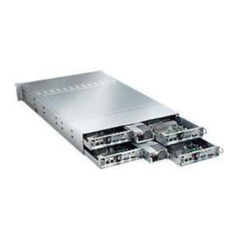
Page 88: Chassis View For R424-E2 And R424-Inf-E2
R424-E2/R424-INF-E2 and R424-F2/R424-INF-F2 Installation and User's Guide Chassis view for R424-E2 and R424-INF-E2 Figure 6-1. Chassis Front View Figure 6-2. Chassis Rear View Chassis view for R424-F2 and R424-INF-F2 Figure 6-3. Chassis Front View Figure 6-4. Chassis Rear View... -
Page 89: Installing And Removing Hard Drives On R424-E2 And R424-Inf-E2
Installing and Removing Hard Drives on R424-E2 and R424-INF-E2 The R424-E2 chassis contains four individual serverboards in separate node drawers. Each serverboard node controls a set of three hard drives. Note that if a serverboard node drawer is pulled out of the chassis, the hard drives associated with that node will power down as well.. -
Page 90: Removing Hard Drive Trays From The Chassis
R424-E2/R424-INF-E2 and R424-F2/R424-INF-F2 Installation and User's Guide Figure 6-6. Removing a Hard Drive Tray Removing Hard Drive Trays from the Chassis Press the release button on the drive tray. This extends the drive bay handle.1. Use the handle to pull the drive out of the chassis. - Page 91 Chapter 6: Advanced Chassis Setup Figure 6-7. Chassis Drive Tray The drives are mounted in drive trays to simplify their installation and removal from the chassis. These trays also help promote proper airfl ow for the drive bays. Warning: Except for short periods of time while swapping hard drives, do not operate the server with the hard drives bays empty.
-
Page 92: Installing A Drive Into The Hard Drive Tray
R424-E2/R424-INF-E2 and R424-F2/R424-INF-F2 Installation and User's Guide Installing a Drive into the Hard Drive Tray Remove the screws (2) holding the drive to the tray. Remove the drive from the tray. Figure 6-9. Removing Hard Drive Install a new drive into the tray with the printed circuit board side facing down so that the mounting holes align with those in the carrier. -
Page 93: Overview
Chapter 6: Advanced Chassis Setup Installing and Removing Hard Drives on R424-F2 and R424-INF-F2 Overview The hard drives are mounted in drive carriers to simplify their installation and removal from the chassis. These carriers also help promote proper airfl ow for the system. -
Page 94: Installing/Removing Hot-Swap Drives
R424-E2/R424-INF-E2 and R424-F2/R424-INF-F2 Installation and User's Guide Figure 6-10. Mounting a Hard Drive in a Carrier Installing/Removing Hot-swap Drives To remove a carrier, push the release button located beside the drive LEDs. Swing the handle fully out and use it to pull the unit straight out (see Figure below). - Page 95 Chapter 6: Advanced Chassis Setup Figure 6-12. Drives and Nodes: Logical Confi guration Note: see Figure above for the locations of the control panels that are associated with each node. Serverboard Drawer Locations in the Chassis Motherboard B Motherboard D Controls HDDs B1, B2 and B3 Controls HDDs D1, D2 and D3 Motherboard A...
-
Page 96: Removing And Installing The Backplane
R424-E2/R424-INF-E2 and R424-F2/R424-INF-F2 Installation and User's Guide Removing and Installing the Backplane The R424-E2 and R424-F2 chassis backplane are located behind the hard drives and in front of the front system fans. Although backplane failure rarely occurs, in the event of a backplane failure, follow the instructions below. - Page 97 Chapter 6: Advanced Chassis Setup Figure 6-18. Loosening the Spring Bar Screws in the Floor of the Chassis Figure 6-19. Removing the Backplane from the Chassis Gently ease the backplane up and out of the chassis at a slight angle. 6-11...
-
Page 98: Installing The Backplane
R424-E2/R424-INF-E2 and R424-F2/R424-INF-F2 Installation and User's Guide Installing the Backplane Installing the Backplane into the Chassis Ensure that all of the hard drive trays have been removed from the bays in the front of the chassis and that the spring bar has been loosened as directed in the previous section. -
Page 99: Installing The Serverboard
Permanent and Optional Standoffs Standoffs prevent short circuits by securing space between the serverboard and the chassis surface. The R424-E2 and R424-F2 chassis include permanent standoffs in locations used by the serverboards. These standoffs accept the rounded Phillips head screws included in the R424-E2 and R424-F2 accessories packaging. -
Page 100: Installing The Serverboard
R424-E2/R424-INF-E2 and R424-F2/R424-INF-F2 Installation and User's Guide Figure 6-22. Installing he Serverboard in the Serverboard Node Drawer Installing the Serverboard Review the documentation that came with your serverboard. Become familiar with component placement, requirements, precautions, and cable connec- tions. - Page 101 Chapter 6: Advanced Chassis Setup Connect the cables between the serverboard, backplane, chassis, front panel, and power supply, as needed. Also, fans may be temporarily removed to al- low access to the backplane ports. Replace the add-on card bracket and secure the bracket with a screw. Repeat steps 3 - 5 for the remaining nodes.
-
Page 102: Installing The Air Shrouds
R424-E2/R424-INF-E2 and R424-F2/R424-INF-F2 Installation and User's Guide Installing the Air Shrouds Air shrouds concentrate air fl ow to maximize fan effi ciency. The R424-E2 and R424-F2 chassis require air shrouds for each serverboard node. Air shrouds vary depending uopn the serverboard used. See the illustrations below. - Page 103 Chapter 6: Advanced Chassis Setup Figure 6-24. Placing air shroud on the serverboard 6-17...
-
Page 104: Checking The Air Flow
Four fans provide cooling for the chassis. These fans circulate air through the chassis as a means of lowering the chassis internal temperature. The R424-E2 and R424-F2 system fans are easy to change modules. There is no need to uninstall any other parts inside the system when replacing fans, and no tools are required for installation. - Page 105 Chapter 6: Advanced Chassis Setup The R424-E2 and R424-F2 model chassis have a default confi guration with one fan wired directly to each motherboard. In the event that one of the motherboard draw- ers is removed, then the fan associated with that motherboard will not function until the drawer is replaced.
-
Page 106: Changing A System Fan
R424-E2/R424-INF-E2 and R424-F2/R424-INF-F2 Installation and User's Guide Changing a System Fan If necessary, open the chassis while the power is running to determine which 1. fan has failed. (Never run the server for an extended period of time with the chassis cover open.) -
Page 107: Power Supply
Chapter 6: Advanced Chassis Setup Power Supply Depending on your chassis model, the R424-E2 and R424-F2 chassis will include a 1200W or 1400W power supply. This power supply is auto-switching capable. This enables it to automatically sense and operate at a 100v to 240v input voltage. -
Page 108: Changing The Power Supply
R424-E2/R424-INF-E2 and R424-F2/R424-INF-F2 Installation and User's Guide Changing the Power Supply Power down all four nodes and unplug the power cord. (Not necessary with redundant power supplies) Unplug the AC power cord from the failed power supply. Push the release tab (on the back of the power supply) as illustrated. - Page 109 Chapter 6: Advanced Chassis Setup 6-10 Power Supply Depending on your chassis model, the R424-E2 and R424-F2 chassis will include a 1200W or 1400W power supply. This power supply is auto-switching capable. This enables it to automatically sense and operate at a 100v to 240v input voltage.
- Page 110 R424-E2/R424-INF-E2 and R424-F2/R424-INF-F2 Installation and User's Guide Changing the Power Supply Power down all four nodes and unplug the power cord. (Not necessary with redundant power supplies) Unplug the AC power cord from the failed power supply. Push the release tab (on the back of the power supply) as illustrated.
-
Page 111: Chapter 7. Troubleshooting
Chapter 7. Troubleshooting Use the following procedures to troubleshoot your system. If you have followed all of the procedures below and still need assistance, contact Bull's Technical Support. Note: Always disconnect the power cord before adding, changing or installing any hardware components. -
Page 112: No Video
R424-E2/R424-INF-E2 and R424-F2/R424-INF-F2 Installation and User's Guide No Video If the power is on but you have no video, remove all the add-on cards and cables. Use the speaker to determine if any beep codes exist. Refer to the Appendix A for details on beep codes. -
Page 113: Chapter 8. Bios
Chapter 8: BIOS Chapter 8. BIOS Introduction This chapter describes the AMI BIOS Setup Utility for the R424-E2/R424- INF-E2 and R424-F2/R424-INF-F2. The AMI ROM BIOS is stored in a Flash EEPROM and can be easily updated. This chapter describes the basic navigation of the AMI BIOS Setup Utility setup screens. -
Page 114: Main Setup
R424-E2/R424-INF-E2 and R424-F2/R424-INF-F2 Installation and User's Guide Starting the Setup Utility Normally, the only visible Power-On Self-Test (POST) routine is the memory test. As the memory is being tested, press the <Delete> key to enter the main menu of the AMI BIOS Setup Utility. -
Page 115: System Overview
Day MM/DD/YY format. The time is entered in HH:MM:SS format. (Note: The time is in the 24-hour format. For example, 5:30 P.M. appears as 17:30:00.) bullx R424-E2/R424-INF-E2 and R424-F2/R424-INF-F2 serverboard • BIOS Build Version: This item displays the BIOS revision used in your sys- tem. -
Page 116: Advanced Setup Confi Gurations
R424-E2/R424-INF-E2 and R424-F2/R424-INF-F2 Installation and User's Guide Advanced Setup Confi gurations Use the arrow keys to select Boot Setup and hit <Enter> to access the submenu items: Boot Features Quick Boot If Enabled, this option will skip certain tests during POST to reduce the time needed for system boot. - Page 117 Chapter 8: BIOS This forces the system to wait until the 'F1' key is pressed if an error occurs. The options are Disabled and Enabled. Hit 'Del' Message Display This feature displays "Press DEL to run Setup" during POST. The options are Enabled and Disabled.
- Page 118 R424-E2/R424-INF-E2 and R424-F2/R424-INF-F2 Installation and User's Guide Processor and Clock Options This submenu allows the user to confi gure the Processor and Clock settings. Ratio CMOS Setting This option allows the user to set the ratio between the CPU Core Clock and the ESB Frequency.
- Page 119 Chapter 8: BIOS Simultaneous Multi-Threading (Available when supported by the CPU) Set to Enabled to use the Simultaneous Multi-Threading Technology, which will result in increased CPU performance. The options are Disabled and Enabled. Active Processor Cores Set to Enabled to use a processor's Second Core and beyond. (Please refer to Intel's web site for more information.) The options are All, 1 and 2.
- Page 120 R424-E2/R424-INF-E2 and R424-F2/R424-INF-F2 Installation and User's Guide Advanced Chipset Control The items included in the Advanced Settings submenu are listed below: CPU Bridge Confi guration QPI Links Speed This feature selects QPI's data transfer speed. The options are Slow-mode, and Full Speed.
-
Page 121: Patrol Scrubbing
Chapter 8: BIOS Patrol Scrubbing A memory error-correction scheme that works in the background looking for and correcting resident errors. The options are Enabled and Disabled. NUMA Support Select Enabled to use the feature of Non-Uniform Memory Access to improve CPU performance. - Page 122 R424-E2/R424-INF-E2 and R424-F2/R424-INF-F2 Installation and User's Guide North Bridge Confi guration This feature allows the user to confi gure the settings for the Intel IOH chip. Crystal Beach/DMA (Direct Memory Access) This feature works with the Intel I/O AT (Acceleration Technology) to accelerate the performance of TOE devices.
- Page 123 Chapter 8: BIOS South Bridge Confi guration This feature allows the user to confi gure the settings for the Intel ICH South Bridge chipset. USB Functions This feature allows the user to decide the number of onboard USB ports to be enabled.
- Page 124 R424-E2/R424-INF-E2 and R424-F2/R424-INF-F2 Installation and User's Guide IDE/SATA/Floppy Confi guration When this submenu is selected, the AMI BIOS automatically detects the pres- ence of the IDE devices and displays the following items: SATA#1 Confi guration If Compatible is selected, it sets SATA#1 to legacy compatibility mode, while selecting Enhanced sets SATA#1 to native SATA mode.
- Page 125 Chapter 8: BIOS Primary IDE Master/Slave, Secondary IDE Master/Slave, Third IDE Master, and Fourth IDE Master These settings allow the user to set the parameters of Primary IDE Master/ Slave, Secondary IDE Master/Slave, Third and Fourth IDE Master slots. Hit <Enter>...
- Page 126 R424-E2/R424-INF-E2 and R424-F2/R424-INF-F2 Installation and User's Guide DMA Mode Select Auto to allow the BIOS to automatically detect IDE DMA mode when the IDE disk drive support cannot be determined. Select SWDMA0 to allow the BIOS to use Single Word DMA mode 0. It has a data transfer rate of 2.1 MBs.
- Page 127 Chapter 8: BIOS IDE Detect Timeout (sec) Use this feature to set the time-out value for the BIOS to detect the ATA, ATAPI devices installed in the system. The options are 0 (sec), 5, 10, 15, 20, 25, 30, and 35. PCI/PnP Confi...
- Page 128 R424-E2/R424-INF-E2 and R424-F2/R424-INF-F2 Installation and User's Guide Remote Access Confi guration Remote Access This allows the user to enable the Remote Access feature. The options are Disabled and Enabled. If Remote Access is set to Enabled, the following items...
- Page 129 Chapter 8: BIOS Hardware Health Monitor This feature allows the user to monitor system health and review the status of each item as displayed. CPU Overheat Alarm This option allows the user to select the CPU Overheat Alarm setting which determines when the CPU OH alarm will be activated to provide warning of possible CPU overheat.
- Page 130 This results in better CPU thermal management. Bull has leveraged this feature by assigning a temperature status to certain thermal conditions in the processor (Low, Medium and High). This makes it easier for the user to understand the CPU’s temperature status, rather than by just simply seeing a temperature...
- Page 131 Chapter 8: BIOS Fan1 ~ Fan 4 Reading This feature displays the fan speed readings from fan interfaces Fan1 through Fan5. Voltage Monitoring The following items will be monitored and displayed: CPU1 Vcore, CPU2 Vcore, +5Vin, +12Vcc (V), VP1 DIMM, VP2 DIMM, 3.3Vcc (V), and Battery Voltage ACPI Confi...
- Page 132 R424-E2/R424-INF-E2 and R424-F2/R424-INF-F2 Installation and User's Guide General WHEA Confi guration WHEA Support Select Enabled to enable Windows Hardware Error Architecture (WHEA) sup- port which will provide a common infrastructure for handling hardware errors on Windows platforms in order to reduce system crashes due to hardware errors and improve system recovery and health monitoring.
- Page 133 Chapter 8: BIOS View BMC System Event Log This feature displays the BMC System Event Log (SEL). It shows the total num- ber of entries of BMC System Events. To view an event, select an Entry Number and pressing <Enter> to display the information as shown in the screen.. •...
- Page 134 R424-E2/R424-INF-E2 and R424-F2/R424-INF-F2 Installation and User's Guide Set LAN Confi guration Set this feature to confi gure the IPMI LAN adapter with a network address as shown in the following graphics.. Channel Number - Enter the channel number for the SET LAN Confi g com- mand.
- Page 135 Chapter 8: BIOS IP Address Confi guration Enter the IP address for this machine. This should be in decimal and in dotted quad form (i.e., 192.168.10.253). The value of each three-digit number sepa- rated by dots should not exceed 255 as shown in the screen below.. Parameter Selector Use this feature to select the parameter of your IP Address confi...
- Page 136 R424-E2/R424-INF-E2 and R424-F2/R424-INF-F2 Installation and User's Guide MAC Address Confi guration Enter the Mac address for this machine. This should be in decimal and in dotted quad form (i.e. 192.168.10.253). The value of each three-digit number separated by dots should not exceed 255 as shown in the screen below.
- Page 137 Chapter 8: BIOS DMI Event Log View Event Log Use this option to view the System Event Log. Mark all events as read This option marks all events as read. The options are OK and Cancel. Clear event log This option clears the Event Log memory of all messages. The options are OK and Cancel.
-
Page 138: Security Settings
R424-E2/R424-INF-E2 and R424-F2/R424-INF-F2 Installation and User's Guide Security Settings The AMI BIOS provides a Supervisor and a User password. If you use both pass- words, the Supervisor password must be set fi rst. Supervisor Password This item indicates if a Supervisor password has been entered for the system. "Not Installed"... -
Page 139: Boot Confi Guration
Chapter 8: BIOS Clear User Password (Available only when User Password has been set) This item allows you to clear a user password after it has been entered. Password Check This item allows you to check a password after it has been entered. The options are Setup and Always. -
Page 140: Exit
R424-E2/R424-INF-E2 and R424-F2/R424-INF-F2 Installation and User's Guide Hard Disk Drives This feature allows the user to specify the boot sequence from all available hard disk drives. The settings are Disabled and a list of all hard disk drives that have been detected (i.e., 1st Drive, 2nd Drive, 3rd Drive, etc). - Page 141 Chapter 8: BIOS Save Changes and Exit When you have completed the system confi guration changes, select this option to leave the BIOS Setup Utility and reboot the computer, so the new system con- fi guration parameters can take effect. Select Save Changes and Exit from the Exit menu and press <Enter>.
-
Page 142: Bios Recovery
R424-E2/R424-INF-E2 and R424-F2/R424-INF-F2 Installation and User's Guide BIOS Recovery Warning! Do not upgrade the BIOS unless your system has a BIOS- related issue. Flashing the wrong BIOS can cause irreparable damage to the system. In no event shall Supermicro be liable for direct, indirect, special, incidental, or consequential damages arising from a BIOS update. -
Page 143: Boot Sector Recovery From An Ide Cd-Rom
Chapter 8: BIOS Boot Sector Recovery from an IDE CD-ROM This process is almost identical to the process of Boot Sector Recovery from a USB device, except that the BIOS image fi le is loaded from a CD-ROM. Use a CD-R or CD-RW drive to burn a CD with the BIOS image fi... - Page 144 R424-E2/R424-INF-E2 and R424-F2/R424-INF-F2 Installation and User's Guide Power on your system and click the <Connect> button in the Hyper Terminal. The terminal screen will display the following messages. Press <SpaceBar> to update BIOS. Confirm update BIOS? (y/n) y Begin remote BIOS flash? (y/n) y Starting remote flash.
- Page 145 Chapter 8: BIOS d. Once the ROM fi le extraction is completed, the message: "New BIOS received OK" will display. Starting FLASH Recovery. NVRAM data will be destroyed CMOS data will be preserved ............... Ending FLASH Recovery FLASH update completed successfully Rebooting...
- Page 146 R424-E2/R424-INF-E2 and R424-F2/R424-INF-F2 Installation and User's Guide 8-34...
-
Page 147: Appendix A. Bios Error Beep Codes
Appendix A: BIOS POST Messages Appendix A. BIOS Error Beep Codes During the POST (Power-On Self-Test) routines, which are performed each time the system is powered on, errors may occur. Non-fatal errors are those which, in most cases, allow the system to continue the boot-up process. - Page 148 R424-E2/R424-INF-E2 and R424-F2/R424-INF-F2 Installation and User's Guide Notes...
-
Page 149: Appendix B. Intel Hostraid Setup Guidelines
Appendix B: Intel HostRAID Setup Guidelines Appendix B. Intel HostRAID Setup Guidelines After all the hardware has been installed, you must fi rst confi gure Intel's IOH-36D SATA RAID before you install the Windows Operating System and other software drivers. Important Notes to the User •... - Page 150 R424-E2/R424-INF-E2 and R424-F2/R424-INF-F2 Installation and User's Guide The Intel HostRAID Confi gurations The following RAID levels are supported: RAID 0 (Data Striping): this writes data in parallel, interleaved ("striped") sections of two hard drives. Data transfer rate is doubled over using a single disk.
- Page 151 Appendix B: Intel HostRAID Setup Guidelines During the system boot-up, press the <Ctrl> and <I> keys simultaneously to run the Intel RAID Confi guration Utility when prompted by the following mes- sage: Press <Ctrl> <I> for the Intel RAID Confi guration Utility. Note: The Intel RAID Confi...
- Page 152 R424-E2/R424-INF-E2 and R424-F2/R424-INF-F2 Installation and User's Guide Creating a RAID 0 Volume a. Select "Create RAID Volume" from the main menu and press the <Enter> key. The following screen will appear: b. Specify a name for the RAID 0 set and press the <Tab> key or the <Enter> key to go to the next fi...
- Page 153 Appendix B: Intel HostRAID Setup Guidelines Creating a RAID 1 Volume a. Select "Create RAID Volume" from the main menu and press the <Enter> key. The following screen will appear: b. Specify a name for the RAID 1 set and press the <Tab> key or the <Enter> key to go to the next fi...
- Page 154 R424-E2/R424-INF-E2 and R424-F2/R424-INF-F2 Installation and User's Guide Creating a RAID 10 (RAID 1+ RAID 0) a. Select "Create RAID Volume" from the main menu and press the <Enter> key. The following screen will appear: b. Specify a name for the RAID 10 set and press <Enter>.
- Page 155 Appendix B: Intel HostRAID Setup Guidelines Creating a RAID 5 Set (Parity) a. Select "Create RAID Volume" from the main menu and press the <Enter> key. The following screen will appear: b. Specify a name for the RAID 5 set and press <Enter>. c.
- Page 156 R424-E2/R424-INF-E2 and R424-F2/R424-INF-F2 Installation and User's Guide i. When asked "Are you sure you want to create this volume (Y/N), press "Y" to create the RAID volume, or type "N" to go back to the Create Volume menu. Deleting a RAID Volume Warning: Make sure you back up your data before deleting a RAID set.
- Page 157 Appendix B: Intel HostRAID Setup Guidelines Resetting to Non-RAID and Resetting a RAID HDD Warning: Be cautious when you reset a RAID volume HDD to non-RAID or Resetting a RAID HDD. Resetting a RAID volume HDD or Resetting a RAID HDD will reformat the HDD and delete the internal RAID structure on the drive.
- Page 158 R424-E2/R424-INF-E2 and R424-F2/R424-INF-F2 Installation and User's Guide B-10...
-
Page 159: Appendix C. Adaptec Hostraid Setup Guidelines
Appendix C: Adaptec HostRAID Setup Guidelines Appendix C. Adaptec HostRAID Setup Guidelines After all the hardware has been installed, you must fi rst confi gure the Adaptec Embedded Serial ATA RAID before you install the Windows operating system. The necessary drivers are all included on the bootable CDs that came packaged with your motherboard. - Page 160 R424-E2/R424-INF-E2 and R424-F2/R424-INF-F2 Installation and User's Guide Confi guring SATA RAID 1. Press the <Del> key during system bootup to enter the BIOS Setup Utility. Note: If it is the fi rst time powering on the system, we recommend you load the Optimized Default Settings.
- Page 161 Appendix C: Adaptec HostRAID Setup Guidelines Adaptec SATA with HostRAID The Adaptec Embedded Serial ATA RAID Controller adds SATA/RAID functional- ity and performance enhancements to a motherboard. RAID striping (RAID 0) allows data to be written across multiple drives, greatly improving hard disk I/O performance.
- Page 162 R424-E2/R424-INF-E2 and R424-F2/R424-INF-F2 Installation and User's Guide Managing Arrays Select this option to view array properties, and configure array settings. To select this option, using the arrow keys and the <enter> key, select "Managing Arrays" from the main menu as shown above.
- Page 163 Appendix C: Adaptec HostRAID Setup Guidelines Configuring Disk Drives You may need to configure a disk drive before you can use it. Caution: Configuring a disk may overwrite the partition table on the disk and may make any data on the disk inaccessible. If the drive is used in an array, you may not be able to use the array again.
- Page 164 R424-E2/R424-INF-E2 and R424-F2/R424-INF-F2 Installation and User's Guide 2. From the "Select Drives for Configuring" List (shown below,) select the drives you want to configure and press <Insert>. 3. The drive you've selected will appear in the "Selected Drives Dialog Box" on the right (as shown below.) Repeat the same steps until all drives that you want...
- Page 165 Appendix C: Adaptec HostRAID Setup Guidelines 5. Read the warning message as shown in the screen below. 6. Make sure that you have selected the correct disk drives to configure. If cor- rect, type Y to continue.
- Page 166 R424-E2/R424-INF-E2 and R424-F2/R424-INF-F2 Installation and User's Guide Creating Arrays Before you create arrays, make sure that the disks for the array are connected and installed in your system. Note that disks with no usable space, or disks that are un-initialized or not formatted are shown in gray and cannot be used. (Note: It is recommended that you configure devices before you create arrays.)
- Page 167 Appendix C: Adaptec HostRAID Setup Guidelines Assigning Array Properties Once a new array is completed, you can assign properties to the array. Caution: Once the array is created and its properties are assigned, and you can- not change the array properties using this utility. To assign properties to the new array: 1.
- Page 168 R424-E2/R424-INF-E2 and R424-F2/R424-INF-F2 Installation and User's Guide 5. When you are finished, press <Done> (as the screen shown below). Notes: 1. Before adding a new drive to an array, be sure to back up any data stored on the new drive; otherwise, all data will be lost.
- Page 169 Appendix C: Adaptec HostRAID Setup Guidelines Adding a Bootable Array To make an array bootable: 1. From the Main menu, select Manage Arrays. 2. From the List of Arrays, select the array you want to make bootable, and press <Ctrl> and <B>. 3.
- Page 170 R424-E2/R424-INF-E2 and R424-F2/R424-INF-F2 Installation and User's Guide Adding/Deleting Hotspares To add a Hotspare: (Note: In order to rebuild a RAID (RAID 0 or RAID 1), you would need to add a new HDD as a hotspare.) 1. From the main menu (shown on Page C-4), select Add/Delete Hotspares.
- Page 171 Appendix C: Adaptec HostRAID Setup Guidelines Viewing Array Properties To view the properties of an existing array: 1. From the main menu, select Manage Arrays and hit <Enter> (as shown on the previous page.) 2. From the List of Arrays dialog box (shown below), select the array you want to view and press Enter.
- Page 172 R424-E2/R424-INF-E2 and R424-F2/R424-INF-F2 Installation and User's Guide Rebuilding Arrays Note 1: Rebuilding applies to Fault Tolerant array (RAID 1) only. If an array Build process is interrupted or when one critical member is missing, you must perform a Rebuild to restore its functionality. For a critical array rebuild operation, the optimal drive is the source drive.
- Page 173 Appendix C: Adaptec HostRAID Setup Guidelines Deleting Arrays Warning!! Back up the data on an array before you delete it to prevent data loss Deleted arrays cannot be restored. To delete an existing array: 1. From the main menu (shown on Page C-4), select Manage Arrays. 2.
-
Page 174: Using The Disk Utilities
R424-E2/R424-INF-E2 and R424-F2/R424-INF-F2 Installation and User's Guide Using the Disk Utilities The Disk Utilities enable you to format or verify the media of your Serial ATA hard disks. To access the disk utilities: 1. From the Adaptec RAID Configuration Utility Menu, select Disk Utilities (as shown above) and press <Enter>. - Page 175 Appendix C: Adaptec HostRAID Setup Guidelines To format a disk: Note: The operation of Formatting Disk allows you to perform a low-level format- ting of a hard drive by writing zeros to the entire disk. Serial ATA drives are low-level formatted at the factory and do not need to be low-level formatted again.
- Page 176 R424-E2/R424-INF-E2 and R424-F2/R424-INF-F2 Installation and User's Guide To verify disk media: 3. When the screen shown above displays, select Verify Disk Media and press <Enter>. 4. A message will display, indicating that the selected drive will be scanned for media defects.
- Page 177 Appendix C: Adaptec HostRAID Setup Guidelines To Exit Adaptec RAID Configuration Utility 1. Once you have completed RAID array configurations, press ESC to exit. The following screen will appear. 2. Press Yes to exit the Utility. C-19...
- Page 178 R424-E2/R424-INF-E2 and R424-F2/R424-INF-F2 Installation and User's Guide C-20...
-
Page 179: Appendix D. System Specifi Cations
Four (4) hot-swap drive bays to house four (4) standard SATA drives PCI Expansion Two (2) low-profi le PCI-Express 2.0 x16 slots (with pre-installed riser cards) Serverboard bullx R424-E2 bullx R424-INF-E2 bullx R424-F2 bullx R424-INF-F2 Dimensions (both): 6.5 x 16.4 in (165 x 417 mm) - Page 180 R424-E2/R424-INF-E2 and R424-F2/R424-INF-F2 Installation and User's Guide...
- Page 182 BULL CEDOC 357 AVENUE PATTON B.P.20845 49008 ANGERS CEDEX 01 FRANCE REFERENCE 86 A1 61FE 01...
Need help?
Do you have a question about the R424-E2 and is the answer not in the manual?
Questions and answers