Krell Industries Evolution Owner's Reference Manual
Stereo, three-channel and monaural amplifiers
Hide thumbs
Also See for Evolution:
- Owner's reference manual (35 pages) ,
- Owner's reference manual (40 pages)

Related Manuals for Krell Industries Evolution


Summary of Contents for Krell Industries Evolution
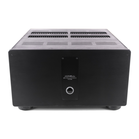
- Page 1 EVOLUTION E V O L U T I O N A M P L I F I E R S 3 0 2 A N D 4 0 2 S T E R E O 4 0 3 T H R E E - C H A N N E L...
-
Page 2: Important Safety Instructions
10. An Evolution amplifier must be placed on a firm, level surface where it is not exposed to drip- ping or splashing. -
Page 3: Table Of Contents
SECTION THREE: Anatomy of the Evolution Amplifier, page 13 Front Panel Description, and Back Panel Description SECTION FOUR: Connecting an Evolution Amplifier to Your System, page 21 CAST Connections, Balanced Connections, Single-ended Connections, Evolution DC Protection Circuitry/Using Tube Preamplifiers, Connection Steps... -
Page 4: List Of Illustrations
Figure 1, page 13 Evolution Amplifier Front Panel Figure 2, page 15 Evolution 302 Back Panel Figure 3, page 16 Evolution 402 Back Panel Figure 4, page 17 Evolution 403 Back Panel Figure 5, page 18 Evolution Monaural Amplifier Back Panel... -
Page 5: A Letter From Dan D'agostino
These four new models utilize Active Cascode Topology, a unique circuit technique that minimizes distortion by applying from 2 to 3 times more active devices to each gain stage. Evolution Series amplifiers bring the real-life dynamics and transparency for which Krell is famous, to a whole new level. -
Page 6: Section One: Evolution Amplifier Features And Technology
The Evolution 302 design utilizes a 3000 VA power supply. The Evolution 402 and Evolution 600 are equipped with a 5000 VA power supply, and the Evolution 403 and Evolution 900 house 6000 VA power supplies. -
Page 7: Revolutionary Krell Cast Technology
Revolutionary Krell CAST Technology Current Audio Signal Transmission, termed CAST, is a revolutionary method of connecting analog audio components for unparalleled sonic performance. Innovative engineering combines the new Krell CAST circuitry with existing Krell Current Mode technology to create entire CAST systems that reproduce music with incredible range, tonality, and precision. - Page 8 By employing revolutionary current mirror circuitry, the Evolution amplifier compo- nents raises CAST technology to another level. This advanced use of the technol- ogy increases the linearity, transient speed, and bandwidth of the Evolution com- ponents while reducing the distortion by an order of magnitude.
-
Page 9: Definition Of Terms
Krell CAST and its circuitry update, Evolution CAST, yield accurate, realistic music reproduction, enabling connected compo- nents to perform as if they are all part of a single circuit. CAST and Evolution CAST are balanced connections, and reject induced noise. - Page 10 (SECTION ONE: Definition of Terms continued) Technology Active Cascode Topology A unique circuit technique that minimizes distortion by applying from 2 to 3 times more active devices to each gain stage thereby reducing the load on individual devices and improving circuit-wide linearity. Krell Current Mode A proprietary Krell circuit topology in which the audio gain stages of a component operate in the current domain rather than the voltage domain.
-
Page 11: Section Two: Unpacking And Placement
Place the amplifier in a safe location, and remove the protective plastic wrap- ping. Note Save all packing materials. If you need to ship the Evolution amplifier in future, repack the unit in its original packaging to prevent shipping damage. continued... -
Page 12: Ac Power Guidelines
CAST technology permits long interconnect cable lengths, keep loudspeaker cable lengths to a minimum. AC Power Guidelines The Evolution amplifier requires a dedicated AC circuit rated at a minimum of 20 amps. Do not use extension cords, multiple AC adapters, or AC power strips. Note Do not operate the Evolution amplifiers with any device designed to alter or condition AC power. -
Page 13: Figure 1
THREE SECTION Anatomy of an Evolution Amplifier This section describes Evolution amplifier functions. Figure 1 Evolution Amplifier Front Panel (Evolution 402 shown) 1 Power Button Power 2 Power Status Indicator continued... -
Page 14: Front Panel Description
Evolution amplifier front panel functions are described below: Power 1 Power Button Press this button to place the Evolution amplifier in operational mode. 2 Power Status Indicator The power status indicator is illuminated in red when the amplifier is in stand- by mode. -
Page 15: Figure 2
Figure 2 Evolution 302 Stereo Amplifier Back Panel Outputs 3 Loudspeaker Binding Posts Inputs 4 CAST Inputs 5 Single-ended Inputs 6 Balanced Inputs 7 12 VDC Out/In (12 V Trigger) Remote 8 Backlight Control Power 9 IEC Power Cord Receptacle... -
Page 16: Figure 3
Figure 3 Evolution 402 Stereo Amplifier Back Panel Outputs 3 Loudspeaker Binding Posts Inputs 4 CAST Inputs 5 Single-ended Inputs 6 Balanced Inputs 7 12 VDC Out/In (12 V Trigger) Remote 8 Backlight Control Power 9 IEC Power Cord Receptacle... -
Page 17: Figure 4
(SECTION THREE: Anatomy of an Evolution Amplifier continued) Figure 4 Evolution 403 Multi-channel Amplifier Back Panel Outputs 3 Loudspeaker Binding Posts Inputs 4 CAST Inputs 5 Single-ended Inputs 6 Balanced Inputs 7 12 VDC Out/In (12 V Trigger) Remote 8 Backlight Control... -
Page 18: Figure 5
Figure 5 Evolution Monaural Amplifier Back Panel (Evolution 600 shown) Outputs 3 Loudspeaker Binding Posts Inputs 4 CAST Input 5 Single-ended Input 6 Balanced Input 7 12 VDC Out/In (12 V Trigger) Remote 8 Backlight Control 9 IEC Power Cord Receptacle... -
Page 19: Back Panel Description
(SECTION THREE: Anatomy of an Evolution Amplifier continued) Back Panel Description See Figure 2, 3, and 4 on the previous pages The amplifier back panel provides access to the input and output connections, 12 V trigger inputs and outputs, and the AC power connection and switch. Back... -
Page 20: Remote Connections
Remote Connections 7 12 VDC In/Out (12 V Trigger) The 12 V trigger allows you to turn the Evolution amplifier on or off, or to and from stand-by, from other components. Out. The output sends 12 VDC (12 V trigger) power on/off signals to other Krell components and other devices that incorporate a 12 V trigger, allowing whole systems or parts of systems to be easily controlled remotely. -
Page 21: Balanced Connections
RCA connector, and a pair of loudspeaker binding posts. The rear panel also has 12 VDC trigger input and outputs, and a backlight remote trigger input. All inputs and outputs are located on the Evolution amplifier back panel. Maintain the correct left/right orientation, when hooking up your system. -
Page 22: Connection Steps
Plug the AC power cord into AC power. Note Use only the power cord provided with the Evolution amplifier to make the connection to AC power. Operation with a power cord other than the one supplied by Krell could induce noise, limit current, or otherwise impair the ability of the amplifier to perform... -
Page 23: Section Five: Evolution Amplifier Operation
It is now safe to place the rest of the system in stand-by. Powering Off Krell recommends leaving Evolution amplifiers powered down (in the stand-by mode, with the back panel power breaker switch on) between listening sessions. Turn the amplifier off using the power breaker switch (10), and disconnect the amplifier from AC power when the system is not being used for an extended peri- od of time. -
Page 24: How To Evaluate Amplifier Operation
This often occurs when introducing a new component into a system. If this happens when you place the Evolution amplifier into your system, follow these simple troubleshooting steps. -
Page 25: Error Codes
(SECTION SIX: Troubleshooting continued) Error Codes In the event of a problem, the power status indicator (2) will flash error code(s) in red. Errors are identified by a sequence of 3, 4, or 5 flashes. There is a pause between codes, and in the case where there is only one error code, the same code is repeated. -
Page 26: Section Seven: Questions And Answers
Krell dealer, distributor, or Krell for suggestions on how to solve this problem. Q. My loudspeakers are rated for 150 Watts. Are the Evolution models too power- ful for them? A. No. A loudspeaker seldom is damaged from overdriving. More often, damage occurs when an amplifier that lacks sufficient power is asked to handle heavy demand situations such as high playback levels. -
Page 27: Warranty
IMPORTANT The single-ended inputs on the Evolution amplifiers are cap-coupled. Use these inputs whenever you are connecting a tube preamplifier. Proof of purchase in the form of a bill of sale or receipted invoice substantiating that the product is within the warranty period must be presented to obtain warranty service. - Page 28 If the product is serviced by a distributor who did not import the unit, there may be a charge for service, even if the product is within the warranty period. Freight to the factory is your responsibility. Return freight within the United States (U.S.A.) is included in the warranty.
-
Page 29: Return Authorization Procedure
Return Authorization Procedure How to Expedite Service If you believe there is a problem with your component, please contact your deal- er, distributor, or the Krell factory to discuss the problem before you return the component for repair. To expedite service, you may wish to complete and e-mail the Service Request Form in the Service section of our website at: http://www.krellonline.com To contact the Krell Service Department:... -
Page 30: Specifications
WEIGHT Shipping Unit only All operational features, functions, specifications, and policies are subject to change without notification Evolution 302 Amplifier 20 Hz to 20 kHz +0, –0.10 dB <0.5 Hz to 180 kHz +0, –3 dB >107 dB >117 dB 25.5 dB... - Page 31 WEIGHT Shipping Unit only All operational features, functions, specifications, and policies are subject to change without notification. Evolution 403 Amplifier 20 Hz to 20 kHz +0, –0.18 dB <0.5 Hz to 120 kHz +0, –3 dB >106 dB >116 dB 25.4 dB...
- Page 32 WEIGHT Shipping Unit only All operational features, functions, specifications, and policies are subject to change without notification Evolution 600 Amplifier 20 Hz to 20 kHz +0, –0.18 dB <0.5 Hz to 120 kHz +0, –3 dB >110 dB >119 dB 25.4 dB...
- Page 33 E V O L U T I O N A M P L I F I E R S 3 0 2 A N D 4 0 2 S T E R E O 4 0 3 T H R E E - C H A N N E L 6 0 0 A N D 9 0 0...
Need help?
Do you have a question about the Evolution and is the answer not in the manual?
Questions and answers