Krell Industries Evolution e series Owner's Reference Manual
Evolution e series
Hide thumbs
Also See for Evolution e series:
- Owner's reference manual (33 pages) ,
- Owner's reference manual (35 pages)
Table of Contents
Advertisement
Advertisement
Table of Contents

Related Manuals for Krell Industries Evolution e series


Summary of Contents for Krell Industries Evolution e series
- Page 1 6 0 0 e A N D 9 0 0 e M O N A U R A L O W N E R ’ S R E F E R E N C E KRELL THE LEADER IN AUDIO ENGINEERING...
-
Page 2: Important Safety Instructions
Krell Industries, LLC, its subsidiaries, and authorized agents. CAST CAST and Krell Current Mode trademarks of Krell Industries, LLC. All other trademarks are registered to their respective companies. © 2010 by Krell Industries, LLC. All rights reserved... -
Page 3: Table Of Contents
Contents List of Illustrations, page 4 A Letter from Krell, page 5 SECTION ONE: Evolution e Series Amplifier Features and Technology, page 6 Features, Revolutionary Krell CAST Technology, Definition of Terms SECTION TWO: Unpacking and Placement, page 11 Opening the Evolution e Series Amplifier Shipping Carton... -
Page 4: List Of Illustrations
List of Illustrations Figure 1, page 13 Evolution e Series Amplifier Front Panel Figure 2, page 15 Evolution 302e Back Panel Figure 3, page 16 Evolution 402e Back Panel Figure 4, page 17 Evolution 403e Back Panel Figure 5, page 18 Evolution e Series Monaural Amplifier Back Pane Figure 6, page 20 Evolution 2250e Back Panel... -
Page 5: A Letter From Krell
A Letter from Krell Industries Dear Audio Enthusiast, Thank you for your purchase of a Krell Evolution e Series amplifier. No component in an audio system contributes more to the full range of musical expression than a power amplifier. The seemingly impossible tasks of simultaneously conveying music's subtle emotional cues and intense dynamic passages rest squarely on its shoulders. - Page 6 Features Evolution e Series 302e, 402e, 403e, 400e, 600e, and 900e amplifiers are designed with a signal path that incorporates Krell Current Mode and CAST circuitry. All amplifiers feature massive power supplies. The power supply makes use of extensive electrical and magnetic shielding to keep radiated interference out of critical amplifier circuits.
-
Page 7: Revolutionary Krell Cast Technology
Krell Current Mode circuitry. This current signal is then output using CAST circuitry. When the signal is received by a CAST input, Krell Current Mode circuitry again takes over until the signal reaches the loudspeaker. By maintaining the musical signal in the current domain from beginning to end, an entire CAST system behaves as if it is one component. -
Page 8: Section One: Evolution E Series Amplifier Features And Technology
The goal for CAST is the same company goal used for all Krell products. Krell strives for the delivery of the best performance of a musical event for you, using the full expression of technology to date. -
Page 9: Definition Of Terms
CAST and Evolution CAST Krell Current Audio Signal Transmission, or CAST, is a proprietary Krell circuit technology for connecting analog components, transmitting the audio waveform between components in the current domain rather than in the voltage domain. The speed and bandwidth provided... - Page 10 Krell Current Mode A proprietary Krell circuit topology in which the audio gain stages of a component operate in the current domain rather than the voltage domain. This unique technology provides the component with exceptional speed, and a wide bandwidth.
-
Page 11: Opening The Evolution E Series Amplifier Shipping Carton
SECTION Unpacking and Placement This section describes the procedures for safely unpacking and placing your Evolution e Series amplifier. The amplifier and accessories are shipped in 1 carton. The dimensions of the amplifier are shown in the specifications section starting on page 30. Two people are needed to remove the Evolution e Series amplifier from its shipping box safely and easily. - Page 12 (SECTION TWO: Unpacking and Placement continued) Placement Before you install an Evolution e Series amplifier into your system, please follow the guidelines in this section to select a location for your component. This will facilitate a clean, trouble-free installation. Place the amplifier on a firm, level surface, away from excessive heat, humidity, or moisture.
-
Page 13: Figure 1
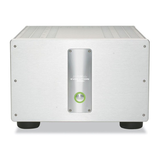
THREE SECTION Anatomy of an Evolution e Series Amplifier This section describes Evolution e Series amplifier functions. Figure 1 Evolution e Series Amplifier Front Panel ( Evolution 402e shown ) EVOLUTION EVOLUTION 402e 402e Power 1 Power Button 2 Power Status Indicator continued... -
Page 14: Front Panel Description
(SECTION THREE: Anatomy of an Evolution e Series Amplifier continued) Front Panel Description See Figure 1 on the previous page Evolution e Series amplifier front panel functions are described below: Power 1 Power Button Press this button to place the Evolution e Series amplifier in operational mode. 2 Power Status Indicator The power status indicator is illuminated in either green or red when the amplifier is in stand-by mode. -
Page 15: Figure 2
(SECTION THREE: Anatomy of an Evolution e Series Amplifier continued) Figure 2 Evolution 302e Stereo Amplifier Back Panel KRELL INDUSTRIES, LLC 45 CONNAIR ROAD ORANGE, CT 06447-3650 3400 W max Outputs 3 Loudspeaker Binding Posts Inputs 4 Single-ended Inputs 5 CAST Inputs... -
Page 16: Figure 3
(SECTION THREE: Anatomy of an Evolution e Series Amplifier continued) Figure 3 Evolution 402e Stereo Amplifier Back Panel 3800 W max KRELL INDUSTRIES, LLC 45 CONNAIR ROAD ORANGE, CT 06447-3650 Outputs 3 Loudspeaker Binding Posts Inputs 4 CAST Inputs 5 Single-ended Inputs... -
Page 17: Figure 4
(SECTION THREE: Anatomy of an Evolution e Series Amplifier continued) Figure 4 Evolution 403e Multi-channel Amplifier Back Panel 5000 W max KRELL INDUSTRIES, LLC 45 CONNAIR ROAD ORANGE, CT 06447-3650 Outputs 3 Loudspeaker Binding Posts Inputs 4 CAST Inputs 5 Single-ended Inputs... -
Page 18: Figure 5
(SECTION THREE: Anatomy of an Evolution e Series Amplifier continued) Figure 5 Evolution 400e Monaural Amplifier Back Panel 2500 W max Outputs 3 Loudspeaker Binding Posts Inputs 4 CAST Input 5 Single-ended Input 6 Balanced Input Remote 7 12 VDC Out/In (12 V Trigger) 8 Backlight Control Power 9 IEC Power Cord Receptacle... - Page 19 (SECTION THREE: Anatomy of an Evolution e Series Amplifier continued) Figure 5 Evolution e Series Monaural Amplifier Back Panel ( Evolution 600e shown ) 3800 W max KRELL INDUSTRIES, LLC 45 CONNAIR ROAD ORANGE, CT 06447-3650 Outputs 3 Loudspeaker Binding Posts...
-
Page 20: Figure 6
(SECTION THREE: Anatomy of an Evolution e Series Amplifier continued) Figure 6 Evolution e Series Stereo Amplifier Back Panel ( Evolution 2250e shown ) 3 Loudspeaker Binding Posts Outputs Inputs 4 Single-ended Input 5 Balanced Input 9 XLR/Sinlge-ended Selector Switch Remote 6 12 VDC Out/In (12 V Trigger) Power... -
Page 21: Figure 7
(SECTION THREE: Anatomy of an Evolution e Series Amplifier continued) Figure 7 Evolution e Series Three Channel Amplifier Back Panel ( Evolution 3250e shown ) Outputs 3 Loudspeaker Binding Posts 4 Single-ended Input Inputs 5 Balanced Input 9 XLR/Sinlge-ended Selector Switch 6 12 VDC Out/In (12 V Trigger) Remote Power... -
Page 22: Back Panel Description
In. The 12 V trigger allows you to turn the Evolution e Series amplifier on or to stand- by from other components. Out. The output sends 12 VDC (12 V trigger) power on/off signals to other Krell components and other devices that incorporate a 12 V trigger, allowing whole systems or parts of systems to be easily controlled remotely. - Page 23 (SECTION THREE: Anatomy of an Evolution e Series Amplifier continued) 8 Backlight Control Ext In. Connect a 12 V trigger to the Ext In input connector to turn off the power status indicator (2) using a remote control. The switch must be set to On/Ext, in order for this to function (see below).
- Page 24 In, The 12 V trigger allows you to turn the Evolution e Series amplifier on or to stand- by from other components. Out. The output sends 12 VDC (12 V trigger) power on/off signals to other Krell components and other devices that incorporate a 12 V trigger, allowing whole systems or parts of systems to be easily controlled remotely.
- Page 25 (SECTION THREE: Anatomy of an Evolution e Series Amplifier continued) Power 7 IEC Power Cord Receptacle The power receptacle is for use with the provided 20 amp AC power cord. Use only the power cord supplied with your Evolution e Series amplifier.
-
Page 26: Balanced Connections
Krell recommends using its proprietary Krell CAST system for unparalleled sonic performance for connections between the Evolution e Series amplifier and other CAST- equipped components. Krell CAST uses flexible interconnecting cables that can be drawn through tight spaces and concealed. -
Page 27: Section Four: Connecting An Evolution E Series Amplifier To Your System
Use only the power cord provided with the Evolution e Series amplifier to make the connection to AC power. Operation with a power cord other than the one supplied by Krell could induce noise, limit current, or otherwise impair the ability of the amplifier to perform optimally. -
Page 28: Figure 8
(SECTION FOUR: Connecting an Evolution e Series Amplifier to Your System continued) Figure 8 Connection Diagram... -
Page 29: On/Off And Stand-By Operation
Always mute or fully attenuate the preamplifier level when switching sources. Do not change input connections to the amplifier when the amplifier is on. Krell amplifiers have large reserves of clean power that can safely drive loudspeakers to higher sound pressure levels than other amplifiers. Use care when setting high playback levels, and lower the volume level at the first sign of loudspeaker distress. -
Page 30: Troubleshooting System Noise
If the hum reappears with one or both interconnect cables reinserted, the cable needs to be checked. If the interconnect cables are sound, you may be experiencing a ground loop. Please contact your authorized Krell dealer, distributor, or Krell for suggestions on how to eliminate the ground loop. continued... -
Page 31: Error Codes
Course of Action 1 flash Internal power supply rail fault Breaker Switch will automatically shut off. Contact your Dealer / Distributor or the Krell Factory 2 flashes Excessive DC at Output Breaker Switch will automatically shut off. Contact your Dealer /... -
Page 32: Questions And Answers
See Troubleshooting System Noise, on page 24. If the interconnects and cables are sound, you may be experiencing a ground loop. This can often be easily eliminated. Please contact your authorized Krell dealer, distributor, or Krell for suggestions on how to solve this problem. -
Page 33: Warranty
Internet do not have any transferrable warranty. The warranty for a Krell product is valid only in the country to which it was originally shipped, through the authorized Krell distributor for that country, and at the factory. There may be restrictions on or changes to the Krell warranty because of regulations within a specific country. - Page 34 The operating voltage of the product is determined by the factory and can only be changed by an authorized Krell distributor or at the factory. The voltage for this product in the U.S.A. cannot be changed until six months from the original purchase date.
-
Page 35: Return Authorization Procedure
Use the original packaging to ensure the safe transit of the product to the factory, dealer, or distributor. Krell may, at its discretion, return a product in new packaging and bill the owner for such packaging if the product received by Krell was boxed in nonstandard packaging or if the original packaging was so damaged that it was unusable. -
Page 36: Specifications
2 balanced via XLR connector 2 CAST via 4-pin bayonet connector 2 CAST via 4-pin bayonet connector OUTPUTS 2 pairs Krell binding posts 2 pairs Krell binding posts DIMENSIONS 17.3 in. W x 9.8 in. H x 20.7 in. D 17.3 in. - Page 37 1 balanced via XLR connector 3 CAST via 4-pin bayonet connector 1 CAST via 4-pin bayonet connector OUTPUTS 3 pairs Krell binding posts 3 pairs Krell binding posts DIMENSIONS 17.3 in. W x 9.8 in. H x 26.1 in. D 14.5 in.
- Page 38 1 balanced via XLR connector 1 CAST via 4-pin bayonet connector 1 CAST via 4-pin bayonet connector OUTPUTS 1 pair Krell binding posts 1 pair Krell binding posts DIMENSIONS 17.3 in. W x 9.8 in. H x 22.1 in. D 17.3 in.
- Page 39 (Specifications continued) Measurement Evolution 2250e Amplifier Evolution 3250e Amplifier FREQUENCY RESPONSE 20 Hz to 20 kHz +0, –0.07 dB 20 Hz to 20 kHz +0, –0.07 dB <0.3 Hz to 150 kHz +0, –3 dB <0.3 Hz to 150 kHz +0, –3 dB SIGNAL-TO-NOISE RATIO >108 dB >108 dB...
- Page 40 E V O L U T I O N S E R I E S A M P L I F I E R S 3 0 2 e A N D 4 0 2 e S T E R E O 4 0 3 e T H R E E - C H A N N E L 6 0 0 e A N D 9 0 0 e...
Need help?
Do you have a question about the Evolution e series and is the answer not in the manual?
Questions and answers