Table of Contents
Advertisement
Quick Links
For more information, visit www.desatech.com
For more information, visit www.desatech.com
VI33NR
VI33PR
REMOTE READY
GAS FIREPLACE
INSERT
WARNING: If the information in this manual is not
followed exactly, a fire or explosion may result caus-
ing property damage, personal injury, or loss of life.
— Do not store or use gasoline or other flammable
vapors and liquids in the vicinity of this or any other
appliance.
— WHAT TO DO IF YOU SMELL GAS
• Do not try to light any appliance.
• Do not touch any electrical switch; do not use any
phone in your building.
• Immediately call your gas supplier from a
neighbor's phone. Follow the gas supplier's in-
structions.
• If you cannot reach your gas supplier, call the fire
department.
— Installation and service must be performed by a quali-
fied installer, service agency, or the gas supplier.
This appliance may be installed in an aftermarket,* permanently located, manufactured
(mobile) home, where not prohibited by local codes.
This appliance is only for use with type of gas indicated on the rating plate. This appliance
is not convertible for use with other gases.
* Aftermarket: Completion of sale, not for purpose of resale, from the manufacturer
Save this manual for future reference.
Save this manual for future reference.
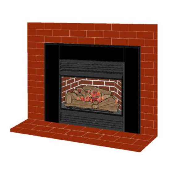
UNVENTED (VENT-FREE)
GAS FIREPLACE INSERT
OWNER'S OPERATION AND
®
INSTALLATION MANUAL
Patent Pending
Shown with GS38
Surround Kit and
G8010 Brick Liner
Accessories
WARNING: Improper installation,
adjustment, alteration, service, or
maintenance can cause injury or
property damage. Refer to this
manual for correct installation and
operational procedures. For assis-
tance or additional information
consult a qualified installer, ser-
vice agency, or the gas supplier.
WARNING: This is an unvented
gas-fired heater. It uses air (oxy-
gen) from the room in which it is
installed. Provisions for adequate
combustion and ventilation air
must be provided. Refer to Air for
Combustion and Ventilation sec-
tion on page 4 of this manual.
Advertisement
Table of Contents

Related Manuals for Vanguard VI33NR


Summary of Contents for Vanguard VI33NR
- Page 1 UNVENTED (VENT-FREE) GAS FIREPLACE INSERT OWNER’S OPERATION AND ® INSTALLATION MANUAL For more information, visit www.desatech.com For more information, visit www.desatech.com VI33NR VI33PR REMOTE READY GAS FIREPLACE Patent Pending INSERT Shown with GS38 Surround Kit and G8010 Brick Liner Accessories...
-
Page 2: Table Of Contents
TABLE OF CONTENTS SAFETY INFORMATION TABLE OF CONTENTS WIRING DIAGRAMS ..............20 SAFETY INFORMATION ............2 SPECIFICATIONS ..............20 PRODUCT IDENTIFICATION ............. 3 TROUBLESHOOTING .............. 21 LOCAL CODES ................4 ILLUSTRATED PARTS BREAKDOWN AND PARTS LIST ..24 UNPACKING ................4 ACCESSORIES ................ -
Page 3: Product Identification
SAFETY INFORMATION PRODUCT IDENTIFICATION SAFETY INFORMATION Continued 12. Do not use this fireplace insert to cook food or burn paper or Carefully supervise young children when they are in other objects. the room with fireplace. When using the hand-held 13. Do not use fireplace insert if any part has been exposed to or remote accessory, keep selector switch in the OFF under water. -
Page 4: Local Codes
LOCAL CODES UNPACKING REMOTE CONTROL ACCESSORIES PRODUCT FEATURES AIR FOR COMBUSTION AND VENTILATION LOCAL CODES PRODUCT FEATURES Install and use fireplace insert with care. Follow all local codes. In OPERATION the absence of local codes, use the latest edition of The National This vent-free fireplace insert is clean burning. - Page 5 AIR FOR COMBUSTION AND VENTILATION Providing Adequate Ventilation Determining Fresh-Air Flow For Heater Location AIR FOR COMBUSTION AND VENTILATION Continued DETERMINING FRESH-AIR FLOW FOR PROVIDING ADEQUATE VENTILATION HEATER LOCATION The following are excerpts from National Fuel Gas Code ANSI Z223.1/NFPA 54, Section 5.3, Air for Combustion and Ventilation. Determining if You Have a Confined or All spaces in homes fall into one of the three following ventilation Unconfined Space...
- Page 6 AIR FOR COMBUSTION AND VENTILATION Determining Fresh-Air Flow For Heater Location (Cont.) Ventilation Air AIR FOR COMBUSTION AND VENTILATION Continued The space in the example on page 5 is a confined space because the actual Btu/Hr used is more than the maximum Btu/Hr the space can support. You 12"...
-
Page 7: Installation
(do not discard). 2. Remove log packaging from firebox cavity. Note: Your Vanguard fireplace insert is designed to be used in zero clearance installations. Wall or framing material can be placed Shoulder directly against any exterior surface on the rear, sides, or top of your... - Page 8 AIR FOR COMBUSTION AND VENTILATION Installing Surround Kit (GS38 or GS43) (Cont.) INSTALLATION Continued 3. Align holes in left surround side panel with screen mounting 8. Remove three pieces of brass trim from packaging. screw holes. Replace 5/16" screen mounting shoulder screws 9.
-
Page 9: Installing Hood
INSTALLATION Installing Surround Kit (GS38 or GS43) (Cont.) Installing Hood Installation Clearances Fireplace Insert Installation Into Masonry Fireplace INSTALLATION Continued Top Brass Trim Set Screws Example Side Brass Adjusting Trim Plate Shim *Minimum 16 inches from Side Wall Figure 12 - Minimum Clearance for Combustible to Wall Slot FIREPLACE INSERT INSTALLATION INTO Mitered... - Page 10 INSTALLATION Fireplace Insert Installation Into Masonry Fireplace (Cont.) Fireplace Insert Installation Into Framed-In Enclosure INSTALLATION Continued 8. Check all gas connections for leaks. See Checking Gas Con- 3. Install gas piping into fireplace location. This installation in- nections, pages 12 and 13. cludes an approved flexible gas line (if allowed by local codes) after the equipment shutoff valve.
-
Page 11: Installing Gas Piping To Fireplace Location
INSTALLATION Fireplace Insert Installation Into Framed-In Enclosure (Cont.) Installing Gas Piping To Fireplace Location Connecting Fireplace Insert To Gas Supply INSTALLATION Continued Mantel Clearances for Insert Installation * A CSA design-certified equipment shutoff valve with 1/8" NPT tap is an acceptable alternative to test gauge connection. Purchase If there is a mantel above masonry fireplace, you must meet the optional CSA design-certified equipment shutoff valve from minimum clearance between mantel shelf and top of fireplace... - Page 12 INSTALLATION Connecting Fireplace Insert To Gas Supply (Cont.) INSTALLATION Continued We recommend that you install a sediment trap in supply line as NOTICE: Most building codes do not permit con- shown in Figure 18. Locate sediment trap where it is within reach for cealed gas connections.
-
Page 13: Checking Gas Connections
INSTALLATION Checking Gas Connections INSTALLATION Continued CHECKING GAS CONNECTIONS 4. Check all joints from gas meter to equipment shutoff valve for natural gas (see Figure 22), or propane/LP supply to equip- ment shutoff valve for propane/LP (see Figure 23). Apply a WARNING: Test all gas piping and connections, noncorrosive leak detection fluid to all joints. -
Page 14: Installing Logs
INSTALLATION Installing Logs INSTALLATION Continued 2. Install fireplace insert screen by slipping notches of fireplace INSTALLING LOGS insert screen over screws on front of fireplace insert (see Fig- ure 26). CAUTION: Do not remove the warning and in- struction labels attached to the heater base assem- WARNING: You must operate this fireplace in- bly. - Page 15 INSTALLATION Optional Wireless Hand-Held Remote Control Accessories (GHRC and GHRCTA) Installing 9-volt Batteries INSTALLATION Continued OPTIONAL WIRELESS HAND-HELD REMOTE Installing 9-Volt Battery (Not Included) in Receiver CONTROL ACCESSORIES (GHRC and GHRCTA) 1. Locate back of receiver under front burner of heater. 2.
-
Page 16: Operating Fireplace Insert
OPERATING FIREPLACE INSERT For Your Safety Read Before Lighting Lighting Instructions OPERATING FIREPLACE INSERT 4. Press in and turn control knob clockwise to the FOR YOUR SAFETY READ OFF position. BEFORE LIGHTING 5. Wait five (5) minutes to clear out any gas. Then smell for gas, including near the floor. -
Page 17: Manual Lighting
OPERATING FIREPLACE INSERT Lighting Instructions (Cont.) To Turn Off Gas To Appliance Manual Lighting Procedure Optional Remote Operation OPERATING FIREPLACE INSERT Continued Thermostat Control Operation WARNING: Make sure the selector switch is in the (Optional GHRCTA Series Only) The thermostat control set- OFF position when you are away from home for long ting on the remote control unit can be set to any comfort level periods of time. -
Page 18: Inspecting Burners
OPERATING FIREPLACE INSERT Optional Remote Operation (Cont.) Optional Blower Operation INSPECTING BURNERS Pilot Flame Pattern OPERATING FIREPLACE INSERT Continued IMPORTANT: This remote control has been specially en- Note: Your gas logs and thermostat blower will not turn on and gineered to take an air temperature sample every 5.5 min- off at the same time. -
Page 19: Cleaning And Maintenance
INSPECTING BURNERS Burner Flame Pattern Burner Primary Air Holes Main Burner CLEANING AND MAINTENANCE Cleaning Burner Injector Holder And Pilot Air Inlet Hole INSPECTING BURNERS CLEANING AND Continued MAINTENANCE BURNER FLAME PATTERN WARNING: Turn off heater and let cool before Figure 39 shows a correct burner flame pattern. -
Page 20: Wiring Diagrams
Figure 44 - Blower Wiring Diagram LOGS • If you remove logs for cleaning, refer to Installing Logs, page SPECIFICATIONS 14, to properly replace logs. • Replace log(s) if broken or chipped (dime-sized or larger). VI33NR VI33PR BURNER PRIMARY AIR HOLES Btu (Variable) 20,000/30,000 20,000/30,000... -
Page 21: Troubleshooting
TROUBLESHOOTING TROUBLESHOOTING WARNING: Turn off heater CAUTION: Never use a wire, and let cool before servicing. Only needle, or similar object to clean Note: For additional help, visit DESA a qualified service person should ODS/pilot. This can damage ODS/ International’s technical service web site service and repair heater. - Page 22 TROUBLESHOOTING TROUBLESHOOTING Continued OBSERVED PROBLEM POSSIBLE CAUSE REMEDY Burner does not light after ODS/pilot is lit 1. Burner orifice clogged 1. Clean burner (see Cleaning and Main- tenance, pages 19 and 20) or replace burner orifice 2. Inlet gas pressure is too low 2.
- Page 23 TROUBLESHOOTING TROUBLESHOOTING Continued WARNING: If you smell gas • Shut off gas supply. • Do not try to light any appliance. • Do not touch any electrical switch; do not use any phone in your building. • Immediately call your gas supplier from a neighbor’s phone. Follow the gas supplier’s instructions.
-
Page 24: Illustrated Parts Breakdown And Parts List
ILLUSTRATED PARTS BREAKDOWN Models VI33NR and VI33PR ILLUSTRATED PARTS BREAKDOWN VI33NR VI33PR Note: Items 27 and 28 are for natural gas only For more information, visit www.desatech.com For more information, visit www.desatech.com 111285-01A... -
Page 25: Parts List
PARTS LIST Models VI33NR and VI33PR PARTS LIST This list contains replaceable parts used in your fireplace insert. When ordering parts, follow the instructions listed under Replace- ment Parts on page 31 of this manual. PART NUMBER NO. VI33NR VI33PR DESCRIPTION QTY. - Page 26 ILLUSTRATED PARTS BREAKDOWN Models VI33NR and VI33PR ILLUSTRATED PARTS BREAKDOWN FIREPLACE INSERT VI33NR VI33PR For more information, visit www.desatech.com For more information, visit www.desatech.com 111285-01A...
- Page 27 PARTS LIST Models VI33NR and VI33PR PARTS LIST FIREPLACE INSERT VI33NR VI33PR This list contains replaceable parts used in your fireplace insert. When ordering parts, follow the instructions listed under Replace- ment Parts on page 31 of this manual. PART NUMBER DESCRIPTION QTY.
-
Page 28: Accessories
ACCESSORIES ACCESSORIES Purchase these fireplace insert accessories from your local dealer. If they can not supply these accessories, call DESA International’s Sales Department at 1-866-672-6040 for information. You can also write to the address listed on the back page of this manual. RECEIVER AND HAND-HELD THERMOSTAT REMOTE CONTROL KIT - GHRCTA SERIES For all models. -
Page 29: Owner's Registration Form
You can register online at www.desatech.com. If access to our website is not available to you, please complete this Owner’s Registration Form and mail to the address on the back of this owner’s manual. Please provide the following product information: Brand: (Comfort Glow, Vanguard, etc.) Model: (EFP33PR, VTGH33NR, etc.) Date Purchased: Note: Keep receipt for warranty verification. - Page 30 Postage Required 2701 Industrial Drive P.O. Box 90004 Bowling Green, KY 42102-9004 For more information, visit www.desatech.com For more information, visit www.desatech.com TAPE 111285-01A...
-
Page 31: Replacement Parts
REPLACEMENT PARTS TECHNICAL SERVICE SERVICE HINTS REPLACEMENT PARTS TECHNICAL SERVICE Note: Use only original replacement parts. This will protect your You may have further questions about installation, operation, or warranty coverage for parts replaced under warranty. troubleshooting. If so, contact DESA International’s Technical Service Department at 1-866-672-6040. -
Page 32: Warranty Information
WARRANTY INFORMATION KEEP THIS WARRANTY Model Serial No. Date Purchased Always specify model and serial numbers when communicating with the factory. We reserve the right to amend these specifications at any time without notice. The only warranty applicable is our standard written warranty. We make no other warranty, expressed or implied.
Need help?
Do you have a question about the VI33NR and is the answer not in the manual?
Questions and answers