Table of Contents
Advertisement
For more information, visit www.desatech.com
For more information, visit www.desatech.com
VI33NR
VI33PR
REMOTE READY
GAS FIREPLACE
INSERT
WARNING: If the information in this manual is not
followed exactly, a fire or explosion may result caus-
ing property damage, personal injury, or loss of life.
— Do not store or use gasoline or other flammable
vapors and liquids in the vicinity of this or any other
appliance.
— WHAT TO DO IF YOU SMELL GAS
• Do not try to light any appliance.
• Do not touch any electrical switch; do not use any
phone in your building.
• Immediately call your gas supplier from a
neighbor's phone. Follow the gas supplier's in-
structions.
• If you cannot reach your gas supplier, call the fire
department.
— Installation and service must be performed by a quali-
fied installer, service agency, or the gas supplier.
This appliance may be installed in an aftermarket,* permanently located, manufactured
(mobile) home, where not prohibited by local codes.
This appliance is only for use with type of gas indicated on the rating plate. This appliance
is not convertible for use with other gases.
* Aftermarket: Completion of sale, not for purpose of resale, from the manufacturer
Save this manual for future reference.
Save this manual for future reference.
UNVENTED (VENT-FREE)
GAS FIREPLACE INSERT
OWNER'S OPERATION AND
®
INSTALLATION MANUAL
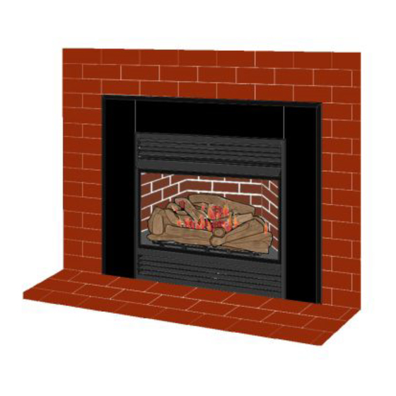
Shown with GS38
Surround Kit and
G8010 Brick Liner
Accessories
WARNING: Improper installation,
adjustment, alteration, service, or
maintenance can cause injury or
property damage. Refer to this
manual for correct installation and
operational procedures. For assis-
tance or additional information
consult a qualified installer, ser-
vice agency, or the gas supplier.
WARNING: This is an unvented
gas-fired heater. It uses air (oxy-
gen) from the room in which it is
installed. Provisions for adequate
combustion and ventilation air
must be provided. Refer to Air for
Combustion and Ventilation sec-
tion on page 5 of this manual.
Advertisement
Table of Contents

Related Manuals for Vanguard VI33NR VI33PR


Summary of Contents for Vanguard VI33NR VI33PR
- Page 1 For more information, visit www.desatech.com For more information, visit www.desatech.com VI33NR VI33PR REMOTE READY GAS FIREPLACE INSERT WARNING: If the information in this manual is not followed exactly, a fire or explosion may result caus- ing property damage, personal injury, or loss of life. —...
-
Page 2: Table Of Contents
TABLE OF CONTENTS SAFETY INFORMATION TABLE OF CONTENTS SAFETY INFORMATION ... 2 LOCAL CODES ... 3 PRODUCT IDENTIFICATION ... 4 UNPACKING ... 4 REMOTE CONTROL ACCESSORIES ... 4 PRODUCT FEATURES ... 4 AIR FOR COMBUSTION AND VENTILATION ... 5 INSTALLATION ... 7 OPERATING FIREPLACE INSERT ... -
Page 3: Safety Information
SAFETY INFORMATION Continued Keep the appliance area clear and free from combus- tible materials, gasoline, and other flammable vapors and liquids. Carefully supervise young children when they are in the room with fireplace. When using the hand-held remote accessory, keep selector switch in the OFF position to prevent children from turning on burners with remote. -
Page 4: Product Identification
PRODUCT IDENTIFICATION UNPACKING REMOTE CONTROL ACCESSORIES PRODUCT FEATURES PRODUCT IDENTIFICATION One Piece Log Set Optional Remote Control Control Knobs Remote Selector Piezo Switch (Optional) Ignitor Figure 1 - Log Base Assembly Top Louver Assembly Firebox Hood Firebox Support Screen Assembly Bottom Louver Assembly Figure 2 - Fireplace Insert... -
Page 5: Air For Combustion And Ventilation
AIR FOR COMBUSTION AND VENTILATION WARNING: This heater shall not be installed in a confined space or unusually tight construction un- less provisions are provided for adequate combus- tion and ventilation air. Read the following instruc- tions to insure proper fresh air for this and other fuel- burning appliances in your home. -
Page 6: Determining Fresh-Air Flow For Heater Location
AIR FOR COMBUSTION AND VENTILATION Determining Fresh-Air Flow For Heater Location Ventilation Air AIR FOR COMBUSTION AND VENTILATION Continued DETERMINING FRESH-AIR FLOW FOR HEATER LOCATION Determining if You Have a Confined or Unconfined Space Use this work sheet to determine if you have a confined or unconfined space. Space: Includes the room in which you will install heater plus any adjoining rooms with doorless passageways or ventilation grills between the rooms. -
Page 7: Installation
AIR FOR COMBUSTION AND VENTILATION Continued Ventilation Air From Outdoors Provide extra fresh air by using ventilation grills or ducts. You must provide two permanent openings: one within 12" of the ceiling and one within 12" of the floor. Connect these items directly to the outdoors or spaces open to the outdoors. -
Page 8: Electrical Hook-Up
INSTALLATION Electrical Hookup Installing Surround Kit INSTALLATION Continued ELECTRICAL HOOKUP (Blower Accessory) This fireplace insert includes a blower assembly with an electrical cord. The electrical cord is five feet in length. You must locate fireplace insert within reach of a 120 volt grounded electrical outlet. If not, install and properly ground GA3555, three-prong 120 volt electrical outlet, in fireplace insert. -
Page 9: Installation Clearances
INSTALLATION Continued 6. Align screw holes in side panels with holes in top panel (see Figure 9). Insert and tighten #10 Phillips screws. 7. Reinstall louver removed in step 4. 8. Carefully inspect fireplace surround assembly. Make sure each part fits properly. -
Page 10: Installing Gas Piping To Fireplace Location
INSTALLATION Installation Clearances (Cont.) Installing Gas Piping To Fireplace Location INSTALLATION Continued Mantel Clearances for Insert Installation If there is a mantel above masonry fireplace, you must meet minimum clearance between mantel shelf and top of fireplace opening (see Figure 12). NOTICE: Surface temperatures of adjacent walls and mantels become hot during operation. - Page 11 INSTALLATION Continued External Regulator Vent Pointing Down Figure 13 - External Regulator with Vent Pointing Down Installation must include an equipment shutoff valve, and plugged 1/8" NPT tap. Locate NPT tap within reach for test gauge hook up. NPT tap must be upstream from fireplace insert (see Figure 14).
-
Page 12: Checking Gas Connections
INSTALLATION Connecting Fireplace Insert To Gas Supply (Cont.) Checking Gas Connections INSTALLATION Continued NOTICE: Most building codes do not permit con- cealed gas connections. A flexible gas line is pro- vided to allow accessibility from the fireplace (see Figure 16). The flexible gas supply line connection to the equipment shutoff valve should be accessible. - Page 13 INSTALLATION Continued Pressure Testing Fireplace Insert Gas Connections 1. Open equipment shutoff valve (see Figure 17, page 12). 2. Open main gas valve located on or near gas meter for natural gas or open propane/LP supply tank valve. Make sure control knob of fireplace insert is in the OFF position. Check all joints from gas meter to equipment shutoff valve for natural gas (see Figure 18, page 12), or propane/LP supply to equipment shutoff valve for propane/LP (see Figure 19, page 12).
-
Page 14: Installing Logs
INSTALLATION Assembling And Attaching Trim (Cont.) Installing Logs INSTALLATION Continued 8. Line up holes in surround trim with holes on side panels of fireplace surround assembly. Attach with screws provided (see Figure 22). 9. Move heater and surround assembly to fireplace opening. Make sure heater and surround assembly fit properly. - Page 15 INSTALLATION Continued OPTIONAL WIRELESS HAND-HELD REMOTE CONTROL ACCESSORIES (GHRCB and GHRCTB) Installing Remote Receiver Unit 1. Disconnect switch wires from the control valve. 2. Remove screws attaching switch plate. 3. Remove switch plate (see Figure 26). Discard after removing. 4. Install remote receiver unit onto gas log heater base using mounting clips.
-
Page 16: Operating Fireplace Insert
OPERATING FIREPLACE INSERT For Your Safety Read Before Lighting Lighting Instructions OPERATING FIREPLACE INSERT FOR YOUR SAFETY READ BEFORE LIGHTING WARNING: If you do not follow these instructions exactly, a fire or explosion may result causing prop- erty damage, personal injury or loss of life. A. -
Page 17: To Turn Off Gas To Appliance
OPERATING FIREPLACE INSERT Continued 10. Wait one minute and switch selector switch to the ON posi- tion to light burners. 11. Set flame adjustment knob to any level between HI and LO. CAUTION: Do not try to adjust heating levels by using the equipment shutoff valve. -
Page 18: Optional Blower Operation
OPERATING FIREPLACE INSERT Optional Hand-Held Remote Operation (Cont.) Optional Blower Operation OPERATING FIREPLACE INSERT Continued THERMOSTAT SERIES (MODEL GHRCTB) The hand-held remote can be operated using either the manual mode (MANU) or thermostatic mode (AUTO) (see Figure 36). To select Fahrenheit/Centigrade mode display, carefully press the ˚C/˚F mode button with the end of a paper clip or similar blunt object. -
Page 19: Inspecting Burners
INSPECTING BURNERS Check pilot flame pattern and burner flame patterns often. PILOT FLAME PATTERN Figure 37 shows a correct pilot flame pattern. Figure 38 shows an incorrect pilot flame pattern. The incorrect pilot flame is not properly heating the thermocouple. When the thermocouple cools, the heater will shut down. -
Page 20: For More Information, Visit Www.desatech.com For More Information, Visit Www.desatech.com
CLEANING AND MAINTENANCE Cleaning Burner Injector Holder And Pilot Air Inlet Hole Logs Burner Primary Air Holes CLEANING AND MAINTENANCE WARNING: Turn off heater and let cool before cleaning. CAUTION: You must keep control areas, burner, and circulating air passageways of heater clean. In- spect these areas of heater before each use. -
Page 21: Wiring Diagrams
WIRING DIAGRAMS Note : For proper operation of optional accessories, the wires from the switch to the control must be connected exactly as shown in Figures 43 and 44. Figure 43 - Switch Wiring Diagram CAUTION: Label all wires prior to disconnection when servicing controls. -
Page 22: Troubleshooting
TROUBLESHOOTING TROUBLESHOOTING Note: For additional help, visit DESA Heating Products’ technical service web site at www.desatech.com. Note: All troubleshooting items are listed in order of operation. OBSERVED PROBLEM When ignitor button is pressed, there is no spark at ODS/pilot When ignitor button is pressed, there is... - Page 23 TROUBLESHOOTING Continued OBSERVED PROBLEM Burner does not light after ODS/pilot is lit Delayed ignition burner Burner backfiring during combustion Slight smoke or odor during initial operation Moisture/condensation noticed on windows Heater produces a whistling noise when burner is lit White powder residue forming within burner box or on adjacent walls or furniture Remote does not function (GHRC and GHRCTA Series only)
- Page 24 TROUBLESHOOTING TROUBLESHOOTING Continued WARNING: If you smell gas • Shut off gas supply. • Do not try to light any appliance. • Do not touch any electrical switch; do not use any phone in your building. • Immediately call your gas supplier from a neighbor’s phone. Follow the gas supplier’s instructions.
-
Page 25: Replacement Parts
If so, contact DESA Heating Products’ Technical Service Department at 1-866-672-6040. When calling please have your model and serial numbers of your heater ready. You can also visit DESA Heating Products’ technical services web site at www.desatech.com. SERVICE HINTS When Gas Pressure Is Too Low •... -
Page 26: Illustrated Parts Breakdownand Parts List
ILLUSTRATED PARTS BREAKDOWN Models VI33NR and VI33PR ILLUSTRATED PARTS BREAKDOWN MODELS VI33NR AND VI33PR For more information, visit www.desatech.com For more information, visit www.desatech.com Note: Items 27 and 28 are for natural gas only 111285-01B... -
Page 27: Parts List
PARTS LIST This list contains replaceable parts used in your fireplace insert. When ordering parts, follow the instructions listed under Replace- ment Parts on page 25 of this manual. NO. VI33NR 102785-03 103779-01 098249-01 099387-14 111331-13 111124-01 099056-26 102772-01 M11084-38 104236-01CK 104236-01CK M12461-26 103284-03... -
Page 28: Illustrated Parts
ILLUSTRATED PARTS BREAKDOWN Models VI33NR and VI33PR ILLUSTRATED PARTS BREAKDOWN FIREPLACE INSERT VI33NR AND VI33PR For more information, visit www.desatech.com For more information, visit www.desatech.com 111285-01B... - Page 29 PARTS LIST FIREPLACE INSERT VI33NR AND VI33PR This list contains replaceable parts used in your fireplace insert. When ordering parts, follow the instructions listed under Replace- ment Parts on page 25 of this manual. ** Not a field replacement part. For more information, visit www.desatech.com For more information, visit www.desatech.com 111285-01B...
-
Page 30: Accessories
ACCESSORIES Purchase these fireplace insert accessories from your local dealer. If they can not supply these accessories, call DESA Heating Prod- ucts’ Sales Department at 1-866-672-6040 for information. You can also write to the address listed on the back page of this manual. -
Page 31: Owner's Registration Form
Address: City: Home Phone: E-Mail: Please answer the following questions to register your product with DESA Heating Products: 1. Where will the product be used? Living/Family Room Office/Warehouse If you bought this product yourself, did you plan to purchase this type of product before going into the store? 3. - Page 32 Postage Required 2701 Industrial Drive P.O. Box 90004 Bowling Green, KY 42102-9004 For more information, visit www.desatech.com For more information, visit www.desatech.com TAPE 111285-01B...
- Page 33 NOTES _______________________________________________________________________________________________ _______________________________________________________________________________________________ _______________________________________________________________________________________________ _______________________________________________________________________________________________ _______________________________________________________________________________________________ _______________________________________________________________________________________________ _______________________________________________________________________________________________ _______________________________________________________________________________________________ _______________________________________________________________________________________________ _______________________________________________________________________________________________ _______________________________________________________________________________________________ _______________________________________________________________________________________________ _______________________________________________________________________________________________ _______________________________________________________________________________________________ _______________________________________________________________________________________________ _______________________________________________________________________________________________ _______________________________________________________________________________________________ _______________________________________________________________________________________________ _______________________________________________________________________________________________ _______________________________________________________________________________________________ _______________________________________________________________________________________________ _______________________________________________________________________________________________ _______________________________________________________________________________________________ _______________________________________________________________________________________________ _______________________________________________________________________________________________ _______________________________________________________________________________________________ _______________________________________________________________________________________________ _______________________________________________________________________________________________ _______________________________________________________________________________________________ _______________________________________________________________________________________________ _______________________________________________________________________________________________ _______________________________________________________________________________________________ _______________________________________________________________________________________________ _______________________________________________________________________________________________ For more information, visit www.desatech.com For more information, visit www.desatech.com 111285-01B NOTES...
-
Page 34: Limited Warranty
DESA Heating Products warrants this product to be free from defects in materials and components for four (4) years from the date of first purchase, provided that the product has been properly installed, operated and maintained in accordance with all applicable instructions. To make a claim under this warranty the Bill of Sale or cancelled check must be presented.
Need help?
Do you have a question about the VI33NR VI33PR and is the answer not in the manual?
Questions and answers