Table of Contents
Advertisement
Quick Links
Advertisement
Table of Contents

Subscribe to Our Youtube Channel
Related Manuals for DFI-ITOX EL330-DR


Summary of Contents for DFI-ITOX EL330-DR
- Page 1 EL330-DR System Board User’s Manual 935-EL3301-050G I08710919...
- Page 2 Copyright This publication contains information that is protected by copyright. No part of it may be reproduced in any form or by any means or used to make any transformation/adaptation without the prior writ- ten permission from the copyright holders. This publication is provided for informational purposes only.
-
Page 3: Fcc And Doc Statement On Class B
FCC and DOC Statement on Class B This equipment has been tested and found to comply with the limits for a Class B digital device, pursuant to Part 15 of the FCC rules. These limits are designed to provide reasonable protection against harmful interference when the equipment is operated in a residential installation. -
Page 4: Table Of Contents
Table of Contents About this Manual................Warranty....................Static Electricity Precaution..............Safety Measures..................About the Package................Before Using the System Board............Chapter 1 - Introduction..............Specifications........................... Features.............................. Chapter 2 - Hardware Installation............ System Board Layout ......................System Memory.......................... CPU............................... Jumper Settings..........................Rear Panel I/O Ports...................... -
Page 5: About This Manual
Warranty 1. Warranty does not cover damages or failures that arised from misuse of the product, inability to use the product, unauthorized replacement or alteration of components and product specifica- tions. 2. The warranty is void if the product has been subjected to physi- cal abuse, improper installation, modification, accidents or unau- thorized repair of the product. -
Page 6: Static Electricity Precaution
Introduction Static Electricity Precautions It is quite easy to inadvertently damage your PC, system board, components or devices even before installing them in your system unit. Static electrical discharge can damage computer components without causing any signs of physical damage. You must take extra care in handling them to ensure against electrostatic build-up. -
Page 7: About The Package
Introduction About the Package The system board package contains the following items. If any of these items are missing or damaged, please contact your dealer or sales representative for assistance. The system board One IDE cable One FDD cable Two USB cables Two Serial ATA data cables Two Serial ATA power cables One bracket mounted with a serial (COM) port... -
Page 8: Chapter 1 - Introduction
Introduction Chapter 1 - Introduction Specifications Processor • LGA 775 socket for: - Intel Core 2 Quad / Intel Core 2 Duo ® ® - Intel Wolfdale 45nm processors ® • Supports Intel Enhanced Memory 64 Technology (EMT64T) • Supports Enhanced Intel SpeedStep Technology (EIST) •... - Page 9 Introduction Rear Panel I/O • 1 mini-DIN-6 PS/2 mouse port Ports • 1 mini-DIN-6 PS/2 keyboard port • 1 DB-25 parallel port • 1 DB-9 serial port • 1 DB-15 VGA port • 2 RJ45 LAN ports • 4 USB 2.0/1.1 ports •...
-
Page 10: Features
Introduction Features The Watchdog Timer function allows your watchdog timer application to regularly “clear” the system at the set time interval. If the system hangs or fails to function, it will reset at the set time interval so that your system will continue to operate. - Page 11 Introduction The two Realtek RTL8111C PCI Express Gigabit gigabit lan controllers suppor t up to 1Gbps data transmis- sion. The system board supports USB 2.0 and USB 1.1 ports. USB 1.1 supports 12Mb/second bandwidth while USB 2.0 suppor ts 480Mb/second bandwidth providing a marked improvement in device transfer speeds between your com- puter and a wide range of simultaneously accessible external Plug and Play peripherals.
- Page 12 Introduction This feature allows the network to remotely wake-on-lan wake up a Soft Power Down (Soft-Off) PC. It is supported via the onboard LAN port or via a PCI LAN card that uses the PCI PME (Power Management Event) signal. However, if your system is in the Suspend mode, you can power-on the system only through an IRQ or DMA interrupt.
- Page 13 Introduction Access Memory) when it powers-off. The operating session will resume exactly where you left off the next time you power-on the system. Important: The 5V_standby power source of your power supply must sup- port ≥ 720mA. When power returns after an AC power fail- Power failure ure, you may choose to either power-on the recovery...
-
Page 14: Chapter 2 - Hardware Installation
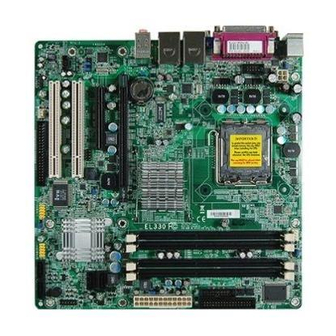
Hardware Installation Chapter 2 - Hardware Installation System Board Layout CPU fan PS/2 power Chassis select ( open PS/2 Mouse PS/2 KB COM 1 +12V power Parallel COM 2 LAN 1 USB 1 USB 0 Realtek RTL8111C LAN 2 Intel USB 3 USB 2 Mic-in... -
Page 15: System Memory
Hardware Installation Warning: Electrostatic discharge (ESD) can damage your system board, proces- sor, disk drives, add-in boards, and other components. Perform the upgrade instruction procedures described at an ESD workstation only. If such a station is not available, you can provide some ESD protec- tion by wearing an antistatic wrist strap and attaching it to a metal part of the system chassis. - Page 16 Hardware Installation The system board supports the following memory interface. Single Channel (SC) Data will be accessed in chunks of 64 bits (8B) from the memory channels. Dual Channel (DC) Data will be accessed in chunks of 128 bits from the memory chan- nels.
-
Page 17: Installing The Dim Module
Hardware Installation Installing the DIM Module Note: The system board used in the following illustrations may not resemble the actual board. These illustrations are for reference only. 1. Make sure the PC and all other peripheral devices connected to it has been powered down. 2. - Page 18 Hardware Installation 6. Grasping the module by its edges, position the module above the socket with the “notch” in the module aligned with the “key” on the socket. The keying mechanism ensures the module can be plugged into the socket in only one way. 7.
-
Page 19: Cpu
Hardware Installation Overview The system board is equipped with a surface mount LGA 775 socket. This socket is exclusively designed for installing a LGA 775 packaged Intel CPU. Important: 1. Before you proceed, make sure (1) the LGA775 socket 1. Before you proceed, make sure (1) the LGA775 socket 1. - Page 20 Hardware Installation Cover 4. The CPU socket comes with a cover that is attached with a remov- able protective cap. The Protective cap cap is used to protect the CPU socket against dust and harmful parti- Lever cles. Remove the protec- tive cap only when you are about to install the CPU.
- Page 21 Hardware Installation 8. Position the CPU above the socket. The gold mark on the CPU must align with pin 1 of the CPU socket. Important: Handle the CPU by its edges and avoid touch- ing the pins. Pin 1 of the socket Gold mark 9.
- Page 22 Hardware Installation 10. Once the CPU is in Cover place, move the cover down. 11. Push the lever down to lock the socket. The lever should hook onto the side tab to indicate that the CPU is com- pletely secured in the Lever socket.
- Page 23 Hardware Installation 2. Place the heat sink on top Mounting hole of the CPU. The 4 studs around the heat sink which Mounting hole are used to secure the heat sink onto the system board must match the 4 mounting holes around the socket.
-
Page 24: Jumper Settings
Hardware Installation Jumper Settings Clear CMOS Data 1-2 On: Normal (default) 2-3 On: Clear CMOS Data If you encounter the following, a) CMOS data becomes corrupted. b) You forgot the supervisor or user password. you can reconfigure the system with the default values stored in the ROM BIOS. - Page 25 Hardware Installation PS/2 Power Select 1-2 On: 5V 2-3 On: (default) 5V_standby JP8 is used to select the power of the PS/2 keyboard/mouse port. Selecting 5V_standby will allow you to use the PS/2 keyboard or PS/2 mouse to wake up the system. BIOS Setting Configure the PS/2 keyboard/mouse wake up function in the Inte- grated Peripherals submenu (“Super IO Device”...
-
Page 26: Usb Power Select
Hardware Installation USB Power Select USB 0-3 1-2 On: 5V 2-3 On: (JP6) (default) 5V_standby USB 4-7 1-2 On: 5V 2-3 On: (JP7) (default) 5V_standby JP6 and JP7 are used to select the power of the USB ports. Select- ing 5V_standby will allow you to use the USB keyboard or USB mouse to wake up the system. - Page 27 Hardware Installation Power-on Select 1-2 On: 2-3 On: Power-on via Power-on via AC power power button (default) JP5 is used to select the method of powering on the system. If you want the system to power-on whenever AC power comes in, set JP5 pins 2 and 3 to On.
-
Page 28: Rear Panel I/O Ports
Hardware Installation Rear Panel I/O Ports PS/2 LAN 1 LAN 2 Parallel Mouse Mic-in Line-in Line-out PS/2 K/B COM 1 USB 0-1 USB 2-3 The rear panel I/O ports consist of the following: • PS/2 mouse port • PS/2 keyboard port •... - Page 29 Hardware Installation PS/2 Mouse and PS/2 Keyboard Ports PS/2 Mouse PS/2 Keyboard These ports are used to connect a PS/2 mouse and a PS/2 key- board. The PS/2 mouse por t uses IRQ12. If a mouse is not connected to this port, the system will reserve IRQ12 for other expansion cards.
- Page 30 Hardware Installation • BIOS Setting: Configure the PS/2 keyboard/mouse wake up function in the In- tegrated Peripherals submenu (“Super IO Device” section) of the BIOS. Refer to chapter 3 for more information. Important: The 5V_standby power source of your power supply must sup- port ≥...
-
Page 31: Parallel Port
Hardware Installation Parallel Port Parallel The parallel port is used for interfacing your PC to a parallel printer. It supports SPP, ECP and EPP. Setting Function Allows normal speed operation but (Standard Parallel Port) in one direction only. Allows parallel port to operate in (Extended Capabilities Port) bidirectional mode and at a speed faster than the SPP’s data transfer... - Page 32 Hardware Installation Serial (COM) Ports COM 1 COM 2 The system board is equipped with an onboard serial port (COM 1). It is also equipped with a 9-pin connector (COM 2). These serial por ts are RS-232 asynchronous communication por ts with 16C550A-compatible UARTs that can be used with modems, serial printers, remote display terminals, and other serial devices.
-
Page 33: Vga Port
Hardware Installation VGA Port The VGA port is used for connecting a VGA monitor. Connect the monitor’s 15-pin D-shell cable connector to the VGA port. After you plug the monitor’s cable connector into the VGA port, gently tighten the cable screws to hold the connector in place. BIOS Setting Configure the onboard VGA in the Advanced Chipset Features submenu of the BIOS. -
Page 34: Universal Serial Bus Connectors
Hardware Installation Universal Serial Bus Connectors USB 1 USB 0 USB 3 USB 2 USB 6-7 USB 4-5 The system board supports 8 USB 2.0/1.1 ports. USB allows data exchange between your computer and a wide range of simultane- ously accessible external Plug and Play peripherals. The USB 4-7 connectors allow you to connect 4 additional USB 2.0/ 1.1 ports. - Page 35 Hardware Installation Driver Installation You may need to install the proper drivers in your operating system to use the USB device. Refer to your operating system’s manual or documentation for more information.
- Page 36 Hardware Installation RJ45 Fast-Ethernet Ports LAN 1 LAN 2 The two onboard RJ45 LAN ports allow the system board to con- nect to a local area network by means of a network hub. BIOS Setting Configure the onboard LAN in the Integrated Peripherals submenu of the BIOS.
- Page 37 Hardware Installation Audio Rear audio Mic-in Line-in Line-out Front audio Rear Panel Audio The system board is equipped with 3 audio jacks. A jack is a one- hole connecting interface for inserting a plug. • Mic-in Jack (Pink) This jack is used to connect an external microphone. •...
- Page 38 Hardware Installation Front Audio The front audio connector allows you to connect to the line-out and mic-in jacks that are at the front panel of your system. Driver Installation Install the audio driver. Refer to chapter 4 for more information.
-
Page 39: I/O Connectors
Hardware Installation I/O Connectors CD-in Internal Audio Connector Ground Ground Right audio Left audio channel channel The CD-in connector is used to receive audio from a CD-ROM drive, TV tuner or MPEG card. - Page 40 Hardware Installation S/PDIF Connector SPDIF out SPDIF in The S/PDIF connector is used to connect an external S/PDIF port. Your S/PDIF port may be mounted on a card-edge bracket. Install the card-edge bracket to an available slot at the rear of the system chassis then connect the audio cable to this connector.
- Page 41 Hardware Installation DIO Connector The DIO (Digital I/O) connector provides powering-on function to an external device that is connected to this connector. Function Pins Function Pins +12V DIO7 +12V DIO6 DIO5 DIO4 DIO3 DIO2 5VSB DIO1 5VSB DIO0...
-
Page 42: Floppy Disk Drive Connector
Hardware Installation Floppy Disk Drive Connector The floppy disk drive connector supports a standard floppy disk drive. The floppy cable can be inserted into this connector only if pin 1 of the cable is aligned with pin 1 of this connector. Connecting the Floppy Disk Drive Cable Install one end of the floppy disk drive cable into the floppy connector on the system board and the other end-most connector... -
Page 43: Serial Ata Connectors
Hardware Installation Serial ATA Connectors SATA 0 SATA 1 SATA 0/1 SATA 2 SATA 3 SATA 2/3 Connect one end of the Serial ATA cable to a Serial ATA connector and the other end to your Serial ATA device. BIOS Setting Configure the onboard Serial ATA in the Integrated Peripherals submenu (“OnChip IDE Device”... -
Page 44: Ide Disk Drive Connectors
Hardware Installation IDE Disk Drive Connectors The IDE connector will interface two Enhanced IDE (Integrated Drive Electronics) disk drives. The IDE cable can be inser ted into this connector only if pin 1 of the cable is aligned with pin 1 of this connector. - Page 45 Hardware Installation The system board suppor ts Enhanced IDE or ATA-2, ATA/33, ATA/66 and ATA/100 hard drives. We recommend that you use hard drives from the same manufacturer. In a few cases, drives from two different manufacturers will not function properly when used to- gether.
-
Page 46: Cooling Fan Connectors
Hardware Installation Cooling Fan Connectors Sense Power Speed Ground Control CPU fan Fan 2 Sense Ground Power The fan connectors are used to connect cooling fans. The cooling fans will provide adequate airflow throughout the chassis to prevent overheating the CPU and system board components. BIOS Setting The “PC Health Status”... - Page 47 Hardware Installation Chassis Open Connector Ground Chassis signal The system board supports the chassis intrusion detection function. Connect the chassis intrusion sensor cable from the chassis to the chassis open connector. When the system’s power is on and a chassis intrusion occurred, an alarm will sound. When the system’s power is off and a chassis intrusion occurred, the alarm will sound only when the system restarts.
-
Page 48: Power Connectors
Hardware Installation Power Connectors Use a power supply that complies with the ATX12V Power Supply Design Guide Version 1.1. An ATX12V power supply unit has a standard 24-pin ATX main power connector that must be inserted into this connector. 1 2 2 4 +3.3VDC +12VDC +5VDC... - Page 49 Hardware Installation The system board requires a minimum of 300 Watt power supply to operate. Your system configuration (CPU power, amount of memory, add-in cards, peripherals, etc.) may exceed the minimum power requirement. To ensure that adequate power is provided, we strongly recommend that you use a minimum of 400 Watt (or greater) power supply.
-
Page 50: Front Panel Connectors
Hardware Installation Front Panel Connectors PWR-LED HDD-LED PWR-BTN RESET SW 1 11 2 HDD-LED - HDD LED This LED will light when the hard drive is being accessed. RESET SW - Reset Switch This switch allows you to reboot without having to power off the system. - Page 51 Hardware Installation Download Flash BIOS Connector...
-
Page 52: Standby Power Led
Hardware Installation Standby Power LED Standby Power LED When the Standby Power LED lit red, it indicates that there is power on the system board. Power-off the PC then unplug the power cord prior to installing any devices. Failure to do so will cause severe damage to the motherboard and components. - Page 53 Hardware Installation PCIE Slots PCIE x16 slot PCIE x4 slot PCI Express x16 Install PCI Express x16 graphics card, that comply to the PCI Ex- press specifications, into the PCI Express x16 slot. To install a graph- ics card into the x16 slot, align the graphics card above the slot then press it down firmly until it is completely seated in the slot.
- Page 54 Hardware Installation Battery Battery The lithium ion battery powers the real-time clock and CMOS memory. It is an auxiliary source of power when the main power is shut off. Safety Measures • Danger of explosion if battery incorrectly replaced. • Replace only with the same or equivalent type recommend by the manufacturer.
-
Page 55: Chapter 3 - Bios Setup
BIOS Setup Chapter 3 - BIOS Setup Award BIOS Setup Utility The Basic Input/Output System (BIOS) is a program that takes care of the basic level of communication between the processor and pe- ripherals. In addition, the BIOS also contains codes for various ad- vanced features found in this system board. -
Page 56: Standard Cmos Features
BIOS Setup Standard CMOS Features Use the arrow keys to highlight “Standard CMOS Features” then press <Enter>. A screen similar to the one below will appear. Phoenix - AwardBIOS CMOS Setup Utility Standard CMOS Features Date <mm:dd:yy> Jan, 06 2009 Item Help Time <hh:mm:ss>... - Page 57 BIOS Setup IDE Channel 0 Master to IDE Channel 2 Slave To configure the IDE drives, move the cursor to a field then press <Enter>. The following screen will appear. Phoenix - AwardBIOS CMOS Setup Utility IDE Channel 0 Master IDE HDD Auto-Detection Press Enter Item Help...
- Page 58 BIOS Setup Capacity Displays the approximate capacity of the disk drive. Usually the size is slightly greater than the size of a formatted disk given by a disk checking program. Cylinder This field displays the number of cylinders. Head This field displays the number of read/write heads. Precomp This field displays the number of cylinders at which to change the write timing.
- Page 59 BIOS Setup Video This field selects the type of video adapter used for the primary system monitor. Although secondary monitors are supported, you do not have to select the type. The default setting is EGA/VGA. EGA/VGA Enhanced Graphics Adapter/Video Graphics Array. For EGA, VGA, SVGA and PGA monitor adapters.
- Page 60 BIOS Setup Extended Memory Displays the amount of extended memory detected during boot-up. Total Memory Displays the total memory available in the system.
-
Page 61: Bios Setup
BIOS Setup Advanced BIOS Features The Advanced BIOS Features allows you to configure your system for basic operation. Some entries are defaults required by the system board, while others, if enabled, will improve the performance of your system or let you set some features according to your preference. Phoenix - AwardBIOS CMOS Setup Utility Advanced BIOS Features Item Help... - Page 62 BIOS Setup CPU Feature This field is used to configure the CPU that is installed on the sys- tem board. Move the cursor to this field then press <Enter>. Phoenix - AwardBIOS CMOS Setup Utility CPU Feature PPM Mode Native Mode Item Help Limit CPUID MaxVal Disabled...
-
Page 63: Hard Disk Boot Priority
BIOS Setup Virtualization Technology When this field is set to Enabled, the VMM can utilize the additional hardware capabilities provided by Vanderpool Technology. Core Multi-Processing The options are Enabled and Disabled. Hard Disk Boot Priority This field is used to select the boot sequence of the hard drives. Move the cursor to this field then press <Enter>. - Page 64 BIOS Setup Many disk diagnostic programs which attempt to access the boot sector table will cause the warning message to appear. If you are running such a program, we recommend that you first disable this field. Quick Power On Self Test This field speeds up Power On Self Test (POST) after you power on the system.
- Page 65 BIOS Setup Typematic Rate Setting Disabled Continually holding down a key on your keyboard will cause the BIOS to report that the key is down. Enabled The BIOS will not only report that the key is down, but will first wait for a moment, and, if the key is still down, it will begin to report that the key has been depressed repeatedly.
- Page 66 BIOS Setup OS Select for DRAM > 64MB This field allows you to access the memory that is over 64MB in OS/2. The options are: Non-OS2 and OS2. Report No FDD For WIN 95 The options are Yes and No. Small Logo(EPA) Show Enabled The EPA logo will appear during system boot-up.
-
Page 67: Advanced Chipset Features
BIOS Setup Advanced Chipset Features Phoenix - AwardBIOS CMOS Setup Utility Advanced Chipset Features System BIOS Cacheable Enabled Item Help Memory Hole At 15M-16M Disabled Menu Level PCI Express Root Port Func Press Enter VT-d Disabled ** VGA Setting ** PEG/Onchip VGA Control Auto On-Chip Frame Buffer Size... - Page 68 BIOS Setup Memory Hole At 15M-16M In order to improve system performance, certain space in memory can be reserved for ISA cards. This memory must be mapped into the memory space below 16MB. When enabled, the CPU assumes the 15- 16MB memory range is allocated to the hidden ISA address range instead of the actual system DRAM.
- Page 69 BIOS Setup PEG/OnChip VGA Control This field is used to select the graphics controller that will serve as the primary boot device. The options are Auto, Onchip VGA and PEG Port. On-Chip Frame Buffer Size This field is used to select the onboard VGA’s frame buffer size that is shared from the system memory.
-
Page 70: Integrated Peripherals
BIOS Setup Integrated Peripherals Phoenix - AwardBIOS CMOS Setup Utility Integrated Peripherals Press Enter OnChip IDE Device Item Help Press Enter Super IO Device Menu Level USB Device Setting Press Enter GLAN1 ROM Disabled Disabled GLAN2 ROM W83627DHG WDT Time ↑↓→←... -
Page 71: Ide Hdd Block Mode
BIOS Setup OnChip IDE Device Move the cursor to this field and press <Enter>. The following screen will appear. Phoenix - AwardBIOS CMOS Setup Utility OnChip IDE Device Item Help IDE HDD Block Mode Enabled IDE DMA Transfer Access Enabled Menu Level IDE Primary Master PIO Auto... - Page 72 BIOS Setup IDE Primary Master/Slave PIO and IDE Secondary Master/Slave PIO means Programmed Input/Output. Rather than have the BIOS issue a series of commands to effect a transfer to or from the disk drive, PIO allows the BIOS to tell the controller what it wants and then let the controller and the CPU perform the complete task by themselves.
- Page 73 BIOS Setup SATA Mode This option configures the Serial ATA drives in IDE mode. RAID This option enables the RAID function for Serial ATA drives. AHCI This option configures the Serial ATA drives in AHCI mode. Legacy Mode Support The options are Enabled and Disabled.
-
Page 74: Power On Function
BIOS Setup Super IO Device Move the cursor to this field and press <Enter>. The following screen will appear. Phoenix - AwardBIOS CMOS Setup Utility Super IO Device Power On Function BUTTON ONLY Item Help Onboard FDC Controller Enabled Menu Level Onboard Serial Port 1 3F8/IRQ4 Onboard Serial Port 2... - Page 75 BIOS Setup Onboard Serial Port 1 and Onboard Serial Port 2 Auto The system will automatically select an I/O address for the onboard serial port 1 and serial port 2. 3F8/IRQ4, 2F8/IRQ3, 3E8/IRQ4, 2E8/IRQ3 Allows manually select an I/O address for the onboard se- rial port 1 and serial port 2.
- Page 76 BIOS Setup PWRON After PWR-Fail When power returns after an AC power failure, the system’s power is off. You must press the Power but- ton to power-on the system. When power returns after an AC power failure, the system will automatically power-on. Former-Sts When power returns after an AC power failure, the system will return to the state where you left off be- fore power failure occurs.
-
Page 77: Usb Device Setting
BIOS Setup USB Device Setting Move the cursor to this field and press <Enter>. The following screen will appear. Phoenix - AwardBIOS CMOS Setup Utility USB Device Setting USB 1.0 Controller Enabled Item Help Enabled USB 2.0 Controller Menu Level USB Operation Mode High Speed USB Keyboard Function... - Page 78 BIOS Setup USB Keyboard Function Due to the limited space of the BIOS ROM, the support for legacy USB keyboard (in DOS mode) is by default set to Disabled. With more BIOS ROM space available, it will be able to support more advanced features as well as provide compatibility to a wide variety of peripheral devices.
-
Page 79: Power Management Setup
BIOS Setup Power Management Setup The Power Management Setup allows you to configure your system to most effectively save energy. Phoenix - AwardBIOS CMOS Setup Utility Power Management Setup PCI Express PM Function Press Enter Item Help ACPI Function Enabled Menu Level S3(STR) ACPI Suspend Type... - Page 80 BIOS Setup Root Port ASPM The options are Disabled, L0s, L1 and L1/L0s. DMI Port ASPM The options are Disabled and L1. ACPI Function This function should be enabled only in operating systems that sup- ® ® ® ® ® port ACPI.
- Page 81 BIOS Setup Video Off Method This determines the manner in which the monitor is blanked. V/H SYNC + Blank This will cause the system to turn off the ver- tical and horizontal synchronization ports and write blanks to the video buffer. Blank Screen This only writes blanks to the video buffer.
- Page 82 BIOS Setup Soft-Off by PWR-BTTN This field allows you to select the method of powering off your system. Delay 4 Sec. Regardless of whether the Power Management func- tion is enabled or disabled, if the power button is pushed and released in less than 4 sec, the system enters the Suspend mode.
- Page 83 BIOS Setup Resume By Alarm Enabled When Enabled, you can set the date and time you would like the Soft Power Down (Soft-Off) PC to power-on in the “Date (of Month) Alarm” and “Time (hh:mm:ss) Alarm” fields. However, if the system is being accessed by incoming calls or the network (Resume On Ring/LAN) prior to the date and time set in these fields, the system will give priority to the incoming calls...
-
Page 84: Init Display First
BIOS Setup PnP/PCI Configurations This section shows how to configure the PCI bus system. It covers some very technical items and it is strongly recommended that only experienced users should make any changes to the default settings. Phoenix - AwardBIOS CMOS Setup Utility PnP/PCI Configurations Init Display First PCI Slot... -
Page 85: Resources Controlled By
BIOS Setup Resources Controlled By The Award Plug and Play BIOS has the capability to automatically configure all of the boot and Plug and Play compatible devices. Auto(ESCD) The system will automatically detect the settings for you. Manual Choose the specific IRQ resources in the “IRQ Re- sources”... - Page 86 BIOS Setup INT Pin 1 Assignment to INT Pin 8 Assignment By default, a device is automatically assigned to each INT. You can also manually assign an INT for each device. Maximum Payload Size This field is used to select the maximum TLP payload size of the PCI Express devices.
-
Page 87: Pc Health Status
BIOS Setup PC Health Status Phoenix - AwardBIOS CMOS Setup Utility PC Health Status Case Open Warning Disabled Item Help CPU Warning Temperature Disabled Menu Level Current System Temp C/96 Current CPU1 Temperature C/95 SYSFAN Speed CPUFAN Speed 865 RPM Vcore 1.25V 5.06V... - Page 88 BIOS Setup Smart CPUFAN Temperature This field is used to select the temperature at which the CPU fan runs at full speed. The temperature will vary within the range of the tolerance value selected in the field below. CPUFAN Tolerance Value This field is used to select the tolerance value of the CPU’s tempera- ture.
-
Page 89: Load Fail-Safe Defaults
BIOS Setup Load Fail-Safe Defaults The “Load Fail-Safe Defaults” option loads the troubleshooting de- fault values permanently stored in the ROM chips. These settings are not optimal and turn off all high performance features. You should use these values only if you have hardware problems. Highlight this option in the main menu and press <Enter>. -
Page 90: Load Optimized Defaults
BIOS Setup Load Optimized Defaults The “Load Optimized Defaults” option loads optimized settings from the BIOS ROM. Use the default values as standard values for your system. Highlight this option in the main menu and press <Enter>. Phoenix - AwardBIOS CMOS Setup Utility Standard CMOS Features Load Fail-Safe Defaults Advanced BIOS Features... -
Page 91: Set Supervisor Password
BIOS Setup Set Supervisor Password If you want to protect your system and setup from unauthorized entry, set a supervisor’s password with the “System” option selected in the Advanced BIOS Features. If you want to protect access to setup only, but not your system, set a supervisor’s password with the “Setup”... -
Page 92: Set User Password
BIOS Setup Set User Password If you want another user to have access only to your system but not to setup, set a user’s password with the “System” option se- lected in the Advanced BIOS Features. If you want a user to enter a password when trying to access setup, set a user’s password with the “Setup”... -
Page 93: Save & Exit Setup
BIOS Setup Save & Exit Setup When all the changes have been made, highlight “Save & Exit Setup” and press <Enter>. Phoenix - AwardBIOS CMOS Setup Utility Standard CMOS Features Load Fail-Safe Defaults Advanced BIOS Features Load Optimized Defaults Advanced Chipset Features Set Supervisor Password Integrated Peripherals Set User Password... -
Page 94: Exit Without Saving
BIOS Setup Exit Without Saving When you do not want to save the changes you have made, high- light “Exit Without Saving” and press <Enter>. Phoenix - AwardBIOS CMOS Setup Utility Standard CMOS Features Load Fail-Safe Defaults Advanced BIOS Features Load Optimized Defaults Advanced Chipset Features Set Supervisor Password... -
Page 95: Intel Raid Bios
BIOS Setup Intel RAID BIOS The Intel RAID BIOS utility is used to configure and manage RAID on Serial ATA drives. After you power up the system and all drives have been detected, the Intel RAID BIOS status message screen will appear. Press the <Ctrl>... -
Page 96: Updating The Bios
BIOS Setup Updating the BIOS To update the BIOS, you will need the new BIOS file and a flash utility, AWDFLASH.EXE. Please contact technical support or your sales representative for the files. 1. Save the new BIOS file along with the flash utility AWDFLASH.EXE to a floppy disk. - Page 97 BIOS Setup 6. The following will appear. Do You Want to Save BIOS (Y/N) This question refers to the current existing BIOS in your system. We recommend that you save the current BIOS and its flash utility; just in case you need to reinstall the BIOS. To save the current BIOS, press <Y>...
-
Page 98: Chapter 4 - Supported Softwares
Supported Software Chapter 4 - Supported Software Drivers for Windows Vista System The CD that came with the system board contains drivers, utilities and software applications required to enhance the performance of the system board. Insert the CD into a CD-ROM drive. The autorun screen (Mainboard Utility CD) will appear. -
Page 99: Intel Chipset Software Installation Utility
Supported Software Intel Chipset Software Installation Utility The Intel Chipset Software Installation Utility is used for updating ® Windows INF files so that the Intel chipset can be recognized and configured properly in the system. To install the utility, click “Intel Chipset Software Installation Utility” on the main menu. - Page 100 Supported Software 3. Go through the readme document for system requirements installation tips then click Next. 4. Setup is now installing the driver. Click Next to continue. 5. After completing installa- tion, click Finish to exit setup.
-
Page 101: Intel Graphics Drivers
Supported Software Intel Graphics Drivers To install the driver, click “Intel Graphics Drivers” on the main menu. 1. Setup is now ready to install the graphics driver. Click Next. By default, the “Automatically run WinSAT and enable the Windows Aero desktop theme” is enabled. With this enabled, after installing the graphics driver and the system rebooted, the screen will turn blank for 1 to 2 minutes (while WinSAT is running) before the Windows Vista desktop appears. - Page 102 Supported Software 2. Read license agreement then click Yes. 3. Go through the readme document for system requirements installation tips then click Next. 4. Setup is now installing the driver. Click Next to continue.
- Page 103 Supported Software 5. Click “Yes, I want to restar t this computer now” then click Finish. Restarting the system will allow the new software installation to take effect.
-
Page 104: Audio Drivers
Supported Software Audio Drivers To install the driver, click “Audio Drivers” on the main menu. 1. Setup is now ready to install the driver. Click Next. 2. Follow the remainder of the steps on the screen; clicking “Next” each time you finish a step. -
Page 105: Lan Drivers
Supported Software LAN Drivers To install the driver, click “LAN Drivers” on the main menu. 1. Setup is now ready to install the driver. Click Next. 2. Click Install to begin installation. 3. After completing installa- tion, click Finish to exit setup. -
Page 106: Hardware Monitor For Windows
Supported Software Hardware Monitor for Windows The Hardware Monitor for Windows utility is capable of monitoring the system’s temperature, fan speed, voltage, etc. and allows you to manually set a range (Highest and Lowest Limit) to the items being monitored. If the settings/values are over or under the set range, a warning message will pop-up. - Page 107 Supported Software 3. Click Next to install or click Browse to select another folder. 4. Click Next to add the program icon to the Program Folder. 5. After completing installa- tion, click Finish to exit setup.
- Page 108 Supported Software 6. Click Yes if you want to create Hardware Doctor shortcut at your desktop. 7. Click “Yes, I want to restar t my computer now” then click Finish. Restarting the system will allow the utility to take effect.
- Page 109 Supported Software Using the Hardware Monitor for Windows Utility 1. When you try to run the utility, which is usually done by double-clicking the Hardware Doctor shor tcut, er ror message will appear. 2. To solve this problem, right-click the Hardware Doctor shor tcut.
- Page 110 Supported Software 4. You can now access the utility.
- Page 111 Supported Software Intel Matrix Storage Manager for RAID/AHCI The Intel Matrix Storage Manager can be installed from within Windows. It allows RAID volume management (create, delete, migrate) from within the operating system. It will also display useful SATA device and RAID volume information.
- Page 112 Supported Software 3. Read license agreement then click Yes. 4. Go through the readme document for system requirements installation tips then click Next. 5. Click “Yes, I want to restar t my computer now” then click Finish. Restarting the system will allow the new software installation to take effect.
- Page 113 Supported Software Adobe Acrobat Reader 7.0 (English Version) To install, click “Adobe Acrobat Reader 7.0 (English Version)” on the main menu. 1. Click Next to continue. 2. Setup is now ready to install. Click Next. 3. Click Next to install or click Change Destination Folder to select another folder.
- Page 114 Supported Software 4. Click Install to begin installation. 5. Click Finish to exit installaion.
- Page 115 Supported Software Installing the AHCI Driver During Windows Vista Installation ® The AHCI driver must be installed during Windows Vista installation. This is required in order to install the operating system onto a hard drive when in AHCI mode. 1. Star t Windows Setup by booting from the installation CD.
- Page 116 Supported Software 4. The screen on the right will appear. Select the driver.
-
Page 117: Creating An Ahci Driver Floppy Diskette Under Vista
Supported Software Creating an AHCI Driver Floppy Diskette under Vista The system board package includes floppy diskettes which are needed when you install the AHCI driver during Windows Vista installation. If in any case you lost the diskette, you can create another one by following the steps below. -
Page 118: Drivers For Windows Xp System
Supported Software Drivers for Windows XP System The CD that came with the system board contains drivers, utilities and software applications required to enhance the performance of the system board. Insert the CD into a CD-ROM drive. The autorun screen (Main Board Utility CD) will appear. If after inserting the CD, "Autorun"... - Page 119 Supported Software Intel Chipset Software Installation Utility The Intel Chipset Software Installation Utility is used for updating ® Windows INF files so that the Intel chipset can be recognized and configured properly in the system. To install the utility, click “Intel Chipset Software Installation Utility” on the main menu.
- Page 120 Supported Software 3. Go through the readme document for system requirements installation tips then click Next. 4. Setup is now installing the driver. Click Next to continue. 5. Click “Yes, I want to restar t this computer now” then click Finish. Restar ting the system will allow the new software installation to...
- Page 121 Supported Software Microsoft DirectX 9.0C Driver To install the driver, click “Microsoft DirectX 9.0C Driver” on the main menu. 1. Click “I accept the agree- ment” then click Next. 2. To start installation, click Next. 3. Click Finish. Reboot the system for DirectX to take effect.
- Page 122 Supported Software Intel Graphics Drivers To install the driver, click “Intel Graphics Drivers” on the main menu. 1. To start installation, click Next. 2. Read license agreement then click Yes. 3. Go through the readme document for system requirements installation tips then click Next.
- Page 123 Supported Software 4. Setup is now installing the driver. Click Next to continue. 5. Click “Yes, I want to restar t this computer now” then click Finish. Restarting the system will allow the new software installation to take effect.
- Page 124 Supported Software Audio Drivers To install the driver, click “Audio Drivers” on the main menu. 1. Setup is now ready to install the audio driver. Click Next. 2. Follow the remainder of the steps on the screen; clicking “Next” each time you finish a step.
- Page 125 Supported Software LAN Drivers To install the driver, click “LAN Drivers” on the main menu. 1. Setup is now ready to install the driver. Click Next. 2. Click Install to begin installation. 3. After completing installa- tion, click Finish to exit setup.
- Page 126 Supported Software Hardware Monitor for Windows The Hardware Monitor for Windows utility is capable of monitoring the system’s temperature, fan speed, voltage, etc. and allows you to manually set a range (Highest and Lowest Limit) to the items being monitored. If the settings/values are over or under the set range, a warning message will pop-up.
- Page 127 Supported Software 3. Click Next to add the program icon to the Program Folder. 4. After completing installa- tion, click Finish to exit setup. 5. Click Yes if you want to create a Hardware Doctor shortcut at your desktop.
- Page 128 Supported Software 6. Click “Yes, I want to restar t my computer now” then click Finish. Restarting the system will allow the driver to take effect.
- Page 129 Supported Software Intel Matrix Storage Manager for RAID/AHCI The Intel Matrix Storage Manager can be installed from within Windows. It allows RAID volume management (create, delete, migrate) from within the operating system. It will also display useful SATA device and RAID volume information.
- Page 130 Supported Software 3. Read license agreement then click Yes. 4. Go through the readme document for system requirements installation tips then click Next. 5. Click “Yes, I want to restar t my computer now” then click Finish. Restarting the system will allow the new software installation to take effect.
-
Page 131: F6 Floppy Configuration Utility
Supported Software F6 Floppy Configuration Utility This is used to create a floppy driver diskette needed when you install ® Windows XP using the F6 installation method. This will allow you to install the operating system onto a hard drive when in AHCI mode. Click “F6 Floppy Configuration Utility”... - Page 132 Supported Software Adobe Acrobat Reader 7.0 (English Version) To install, click “Adobe Acrobat Reader 7.0 (English Version)” on the main menu. 1. Click Next to continue. 2. Setup is now ready to install. Click Next. 3. Click Next to install or click Change Destination Folder to select another folder.
- Page 133 Supported Software 4. Click Install to begin installation. 5. Click Finish to exit installaion.
-
Page 134: Installing The Ahci Driver During Windows Xp Installation
Supported Software Installing the AHCI Driver During Windows XP Installation ® The AHCI driver must be installed during the Windows installation using the F6 installation method. This is required in order to install the operating system onto a hard drive when in AHCI mode. -
Page 135: Chapter 5 - Raid
RAID Chapter 5 - RAID The Intel ICH10DO chip alows configuring RAID on Serial ATA drives. It supports RAID 0, RAID 1, RAID 0+1 and RAID 5. RAID Levels RAID 0 (Striped Disk Array without Fault Tolerance) RAID 0 uses two new identical hard disk drives to read and write data in parallel, interleaved stacks. - Page 136 RAID Settings To enable the RAID function, the following settings are required. 1. Connect the Serial ATA drives. 2. Configure Serial ATA in the Award BIOS. 3. Configure RAID in the RAID BIOS. 4. Install the RAID driver during OS installation. 5.
- Page 137 RAID Step 4: Install the RAID Driver During OS Installation ® The RAID driver must be installed during the Windows XP or ® Windows 2000 installation using the F6 installation method. This is required in order to install the operating system onto a hard drive or RAID volume when in RAID mode or onto a hard drive when in AHCI mode.
-
Page 138: Appendix A - Watchdog Timer
Watchdog Timer Appendix A - Watchdog Timer Watchdog Timer The following parameters are references for setting the time interval of the Watchdog Timer function. The system will regularly be “cleared” according to the set time interval. If the system hangs or fails to function, it will also reset according to the time interval so that your system will continue to operate. -
Page 139: Watchdog Timer
Watchdog Timer endM mSuperio_LDN_Select Macro mSuperio_Set_Reg 07h, LDN endM mSuperio_Set_Reg Macro RegIndex, SetValue dx, SuperIo_CFG_Port al, RegIndex out dx, al NEWIODELAY dx, SuperIo_DAT_Port al, SetValue out dx, al NEWIODELAY endM NEWIODELAY Macro out 0EBh, al ;Dummy I/O output for delay endM .code star t:... -
Page 140: Appendix B - System Error Message
System Error Message Appendix B - System Error Message When the BIOS encounters an error that requires the user to cor- rect something, either a beep code will sound or a message will be displayed in a box in the middle of the screen and the message, PRESS F1 TO CONTINUE, CTRL-ALT-ESC or DEL TO ENTER SETUP, will be shown in the information box at the bottom. - Page 141 System Error Message Hard Disk(s) fail (80) HDD reset failed. Hard Disk(s) fail (40) HDD controller diagnostics failed. Hard Disk(s) fail (20) HDD initialization error. Hard Disk(s) fail (10) Unable to recalibrate fixed disk. Hard Disk(s) fail (08) Sector Verify failed. Keyboard is locked out - Unlock the key The BIOS detects that the keyboard is locked.
-
Page 142: Appendix C - Troubleshooting
Troubleshooting Appendix C - Troubleshooting Troubleshooting Checklist This chapter of the manual is designed to help you with problems that you may encounter with your personal computer. To efficiently troubleshoot your system, treat each problem individually. This is to ensure an accurate diagnosis of the problem in case a problem has multiple causes. -
Page 143: Power Supply
Troubleshooting The picture seems to be constantly moving. 1. The monitor has lost its vertical sync. Adjust the monitor’s vertical sync. 2. Move away any objects, such as another monitor or fan, that may be creating a magnetic field around the display. 3. -
Page 144: Hard Drive
Troubleshooting Hard Drive Hard disk failure. 1. Make sure the correct drive type for the hard disk drive has been entered in the BIOS. 2. If the system is configured with two hard drives, make sure the bootable (first) hard drive is configured as Master and the sec- ond hard drive is configured as Slave. - Page 145 Troubleshooting Keyboard Nothing happens when a key on the keyboard was pressed. 1. Make sure the keyboard is properly connected. 2. Make sure there are no objects resting on the keyboard and that no keys are pressed during the booting process. System Board 1.
Need help?
Do you have a question about the EL330-DR and is the answer not in the manual?
Questions and answers