Table of Contents
Advertisement
Quick Links
Advertisement
Table of Contents

Subscribe to Our Youtube Channel
Related Manuals for DFI-ITOX SB331-IPM


Summary of Contents for DFI-ITOX SB331-IPM
- Page 1 SB331-IPM System Board User’s Manual A18450238...
-
Page 2: Copyright
Copyright This publication contains information that is protected by copyright. No part of it may be reproduced in any form or by any means or used to make any transfor- mation/adaptation without the prior written permission from the copyright hold- ers. -
Page 3: Fcc And Doc Statement On Class B
FCC and DOC Statement on Class B This equipment has been tested and found to comply with the limits for a Class B digital device, pursuant to Part 15 of the FCC rules. These limits are designed to provide reasonable protection against harmful interference when the equipment is operated in a residential installation. -
Page 4: Table Of Contents
Introduction Table of Contents Copyright ................... 2 Trademarks ..................2 FCC and DOC Statement on Class B ..........3 About this Manual ................6 Warranty ..................6 Static Electricity Precautions ............. 7 Safety Measures ................. 7 About the Package ................8 Before Using the System Board ............ - Page 5 Introduction ................39 I/O Connectors S/PDIF Connector ..............39 SATA (Serial ATA) Connectors ............ 40 Cooling Fan Connectors ............. 41 Power Connectors ..............42 Standby Power LED ..............43 Front Panel Connectors ............. 44 Expansion Slots ............... 45 Battery ................... 46 SPI JTAG Connector..............
-
Page 6: About This Manual
Introduction About this Manual An electronic file of this manual is included in the CD. To view the user’s manual in the CD, insert the CD into a CD-ROM drive. The autorun screen (Main Board Utility CD) will appear. Click “User’s Manual” on the main menu. Warranty 1. -
Page 7: Static Electricity Precautions
Introduction Static Electricity Precautions It is quite easy to inadvertently damage your PC, system board, components or devices even before installing them in your system unit. Static electrical dis- charge can damage computer components without causing any signs of physical damage. -
Page 8: About The Package
Introduction About the Package The system board package contains the following items. If any of these items are missing or damaged, please contact your dealer or sales representative for as- sistance. One system board Two Serial ATA data cables ... -
Page 9: Chapter 1 - Introduction
Introduction Chapter 1 - Introduction Specifications Processor • LGA 1155 socket for: generation Intel Core processors (22nm process ® technology) : Intel Core i7-3770 (8M Cache, up to 3.9GHz); 77W ® : Intel Core i5-3550S (6M Cache, up to 3.7GHz); 65W ®... - Page 10 Introduction • 6 Serial ATA ports Serial ATA - 4 SATA 2.0 ports with data transfer rate up to 3Gb/s - 2 SATA 3.0 ports with data transfer rate up to 6Gb/s • Integrated Advanced Host Controller Interface (AHCI) con- troller •...
- Page 11 Introduction • Monitors CPU/system temperature and overheat alarm D a m a g e F r e e • Monitors VCORE/5V/3.3V/V_DIMM/12V/5VSB voltages and Intelligence failure alarm • Monitors CPU/system fan speed and failure alarm • Read back capability that displays temperature, voltage and fan speed •...
-
Page 12: Features
Introduction Features Watchdog Timer The Watchdog Timer function allows your application to regularly “clear” the sys- tem at the set time interval. If the system hangs or fails to function, it will reset at the set time interval so that your system will continue to operate. DDR3 DDR3 delivers increased system bandwidth and improved performance. - Page 13 Introduction Serial ATA Serial ATA is a storage interface that is compliant with SATA 1.0a specifica- tion. SATA 3.0 supports speed up to 6Gb/s while SATA 2.0 supports speed up to 3Gb/s. This improves hard drive performance faster than the standard parallel ATA whose data transfer rate is 100MB/s.
- Page 14 Introduction RTC Timer The RTC installed on the system board allows your system to automatically pow- er-on on the set date and time. ACPI STR The system board is designed to meet the ACPI (Advanced Configuration and Power Interface) specification. ACPI has energy saving features that enables PCs to implement Power Management and Plug-and-Play with operating systems that support OS Direct Power Management.
-
Page 15: Chapter 2 - Hardware Installation
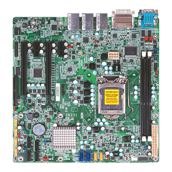
Hardware Installation Chapter 2 - Hardware Installation System Board Layout COM1 RS232/422/485 COM1 RS232/Power select ( select ( COM2 RS232/Power COM2 RS232/422/485 PS/2 power select ( select ( select (J ATX power PS/2 KB/Mouse Connector DDR3_2 Front panel COM 1 COM 2 DDR3_1 Power-on... -
Page 16: System Memory
Hardware Installation Important: Electrostatic discharge (ESD) can damage your system board, processor, disk drives, add-in boards, and other components. Perform the upgrade instruction procedures described at an ESD workstation only. If such a station is not available, you can provide some ESD protection by wearing an antistatic wrist strap and attaching it to a metal part of the system chassis. -
Page 17: Hardware Installation
Hardware Installation The system board supports the following memory interface. Single Channel (SC) Data will be accessed in chunks of 64 bits (8B) from the memory channels. Dual Channel (DC) Data will be accessed in chunks of 128 bits from the memory channels. Dual channel provides better system performance because it doubles the data transfer rate. -
Page 18: Installing The Dim Module
Hardware Installation Installing the DIM Module Note: The system board used in the following illustrations may not resemble the actual board. These illustrations are for reference only. 1. Make sure the PC and all other peripheral devices connected to it has been powered down. - Page 19 Hardware Installation 6. Grasping the module by its edges, position the module above the socket with the “notch” in the module aligned with the “key” on the socket. The keying mechanism ensures the module can be plugged into the socket in only one way.
-
Page 20: Cpu
Hardware Installation The system board is equipped with a surface mount LGA 1155 socket. This sock- et is exclusively designed for installing a LGA 1155 packaged Intel CPU. Important: 1. Before you proceed, make sure (1) the LGA 1155 socket comes with a protective cap, (2) the cap is not damaged and (3) the socket’s contact pins are not bent. -
Page 21: Installing The Cpu
Hardware Installation Installing the CPU 1. Make sure the PC and all other peripheral devices connected to it has been powered down. 2. Disconnect all power cords and cables. 3. Locate the LGA 1155 CPU s o c k e t o n t h e s y s t e m board. - Page 22 Hardware Installation 5. Lifting the load lever will at Load lever the same time lift the load plate. Lift the load lever up to the angle shown on the Load photo. plate 6. Remove the protective cap from the CPU socket. The cap is used to protect the CPU socket against dust and harmful particles.
- Page 23 Hardware Installation 7. Insert the CPU into the socket. The gold triangu- lar mark on the CPU must align with the corner of the CPU socket shown on the photo. Gold triangular mark The CPU’s notch will at Alignment key the same time fit into the socket’s alignment key.
- Page 24 Hardware Installation 8. Close the load plate then push the load lever down. While closing the load plate, make sure the front Retention edge of the load plate knob slides under the retention knob. 9. Hook the load lever under Load lever the retention tab.
-
Page 25: Jumper Settings
Hardware Installation Jumper Settings Clear CMOS Data 2-3 On: Clear CMOS Data JP10 1-2 On: Normal (default) If you encounter the following, a) CMOS data becomes corrupted. b) You forgot the supervisor or user password. you can reconfigure the system with the default values stored in the ROM BIOS. To load the default values stored in the ROM BIOS, please follow the steps below. 1. -
Page 26: Ps/2 Power Select
Hardware Installation PS/2 Power Select 1-2 On: +5V (default) 2-3 On: +5V_standby JP7 is used to select the power of the PS/2 keyboard and PS/2 mouse ports. Se- lecting +5V_standby will allow you to use the PS/2 keyboard or PS/2 mouse to wake up the system. -
Page 27: Usb Power Select
Hardware Installation USB Power Select 1-2 On: +5V 2-3 On: (default) +5V_standby USB 0-1/10-11 (JP3) USB 8-9 (JP4) USB 4-5/2-3 (JP9) USB 12-13/6-7 (JP8) 1-2 On: +5V 2-3 On: (default) +5V_standby These jumpers are used to select the power of the USB ports. Selecting +5V_standby will allow you to use a USB device to wake up the system. -
Page 28: Power-On Select
Hardware Installation Power-on Select JP11 1-2 On: Power-on via power button (default) 2-3 On: Power-on via AC power; or Power-on via WOL after G3 To power-on via WOL after G3: 1. Set JP11 pins 2 and 3 to On. 2. Set the “After G3” field to Power Off/WOL. 3. Set the “GbE Wake Up From S5” to Enabled. The BIOS fields are in the “South Bridge Configuration” submenu (Chipset menu) of the AMI BIOS utility. -
Page 29: Com1/Com2 Rs232/Rs422/Rs485 Select
Hardware Installation COM1/COM2 RS232/RS422/RS485 Select COM 2 COM 1 JP5 (for COM1) and JP6 (for COM2) are used to configure the COM ports to RS232, RS422 (Full Duplex) or RS485. The pin function of the COM ports will vary according to the jumper’s setting. JP5 / JP6 1-2 On: RS232 3-4 On: RS422... -
Page 30: Com1/Com2 Rs232/Power Select
Hardware Installation COM1/COM2 RS232/Power Select JP1 and JP2 are used to configure COM 1 and COM 2 to pure RS232 or RS232 with power. The pin function of COM 1 and COM 2 will vary according to JP1’s and JP2’s set- ting respectively. -
Page 31: Rear Panel I/O Ports
Hardware Installation Rear Panel I/O Ports LAN1 LAN2 LAN3 COM 2 DVI-I COM 1 USB 0-1 USB 10-11 USB 8-9 HDMI The rear panel I/O ports consist of the following: • 2 COM ports • HDMI port • DVI-I port • 3 LAN ports • 6 USB ports... -
Page 32: Com (Serial) Ports
Hardware Installation COM (Serial) Ports COM 2 COM 1 COM 1 and COM 2: RS232/422/485 COM 1 to COM 2 are fixed at RS232. The pin function of COM 1 and COM 2 ports will vary according to JP5/JP6’s set- ting. Refer to “COM1/COM2 RS232/RS422/RS485 Select” in this chapter for more information. The serial ports are asynchronous communication ports with 16C550A-compatible UARTs that can be used with modems, serial printers, remote display terminals, and other serial devices. -
Page 33: Hdmi Port
Hardware Installation HDMI Port HDMI The HDMI port which carries both digital audio and video signals is used to con- nect a LCD monitor or digital TV that has the HDMI port. -
Page 34: Dvi-I Port
Hardware Installation DVI-I Port DVI-I The DVI-I port is used to connect an LCD monitor. Connect the display device’s cable connector to the DVI-I port. After you plug the cable connector into the port, gently tighten the cable screws to hold the connec- tor in place. BIOS Setting Configure the display device in the Chipset menu (“North Bridge Configuration” submenu) of the BIOS. Refer to chapter 3 for more information. -
Page 35: Rj45 Lan Ports
Hardware Installation RJ45 LAN Ports LAN Ports Features • Intel W82579LM with iAMT7.0 Gigabit Ethernet Phy • Intel W82574 PCI Express Gigabit Ethernet controller The LAN ports allow the system board to connect to a local area network by means of a network hub. BIOS Setting Configure the onboard LAN in the Chipset menu (“South Bridge Configuration” submenu) of the BIOS. Refer to chapter 3 for more information. -
Page 36: Usb Ports
Hardware Installation USB Ports USB 0-1 USB 10-11 USB 8-9 USB 12-13 USB 2-3 USB 6-7 USB 4-5 USB allows data exchange between your computer and a wide range of simulta- neously accessible external Plug and Play peripherals. The system board is equipped with four onboard USB 2.0/1.1 ports. The four 10-pin connectors allow you to connect 8 additional USB 2.0/1.1 ports. The ad- ditional USB ports may be mounted on a card-edge bracket. Install the card-edge bracket to an available slot at the rear of the system chassis and then insert the USB port cables to a connector. - Page 37 Hardware Installation Wake-On-USB Keyboard/Mouse The Wake-On-USB Keyboard/Mouse function allows you to use a USB keyboard or USB mouse to wake up a system from the S3 (STR - Suspend To RAM) state. To use this function: • Jumper Setting JP3, JP4, JP8 and/or JP9 must be set to “2-3 On: +5V_standby”. Refer to “USB Power Select” in this chapter for more information.
-
Page 38: Audio
Hardware Installation Audio Front Audio The front audio connector allows you to connect to the second line-out and mic- in jacks that are at the front panel of your system. BIOS Setting Configure the onboard audio in the Chipset menu (“South Bridge Configuration” submenu) of the BIOS. Refer to chapter 7 for more information. Driver Installation Install the audio driver. Refer to chapter 8 for more information. -
Page 39: I/O Connectors
Hardware Installation I/O Connectors S/PDIF Connector SPDIF out Ground SPDIF in The S/PDIF connector is used to connect an external S/PDIF port. Your S/PDIF port may be mounted on a card-edge bracket. Install the card-edge bracket to an available slot at the rear of the system chassis then connect the audio cable to the S/PDIF connector. Make sure pin 1 of the audio cable is aligned with pin 1 of the S/PDIF connector. -
Page 40: Sata (Serial Ata) Connectors
Hardware Installation SATA (Serial ATA) Connectors SATA 3.0 6Gb/s SATA 0 SATA 1 SATA 2.0 3Gb/s SATA 4 SATA 3 SATA 5 SATA 2 Features • SATA 0 and SATA 1 support data transfer rate up to 6Gb/s • SATA 2 to SATA 5 support data transfer rate up to 3Gb/s SATA 4 provides adequate space for SATA DOM • Integrated Advanced Host Controller Interface (AHCI) controller • Supports RAID 0, RAID 1, RAID 5 and RAID 10 The Serial ATA connectors are used to connect Serial ATA devices. Connect one end of the Serial ATA cable to a SATA connector and the other end to your Serial ATA device. BIOS Setting Configure the Serial ATA drives in the Advanced menu (“IDE Configuration” sub- menu) of the BIOS. Refer to chapter 3 for more information. -
Page 41: Cooling Fan Connectors
Hardware Installation Cooling Fan Connectors Speed Control Sense Power Ground CPU fan Ground Power Sense System fan The fan connectors are used to connect cooling fans. The cooling fans will provide adequate airflow throughout the chassis to prevent overheating the CPU and sys- tem board components. BIOS Setting The Advanced menu (“Hardware Health Configuration” submenu) of the BIOS will display the current speed of the cooling fans. Refer to chapter 3 for more infor- mation. -
Page 42: Power Connectors
Hardware Installation Power Connectors ATX power Ground 12V power Use a power supply that complies with the ATX12V Power Supply Design Guide Version 1.1. An ATX12V power supply unit has a standard 24-pin ATX main power connector that must be inserted into the 24-pin connector. The 8-pin +12V power connector enables the delivery of more +12VDC current to the processor’s Volt- age Regulator Module (VRM). The power connectors from the power supply unit are designed to fit the 24-pin and 8-pin connectors in only one orientation. Make sure to find the proper orien- tation before plugging the connectors. -
Page 43: Standby Power Led
Hardware Installation Standby Power LED Standby Power LED This LED will lit red when the system is in the standby mode. It indicates that there is power on the system board. Power-off the PC then unplug the power cord prior to installing any devices. Failure to do so will cause severe damage to the motherboard and components. -
Page 44: Front Panel Connectors
Hardware Installation Front Panel Connectors PWR-LED HDD-LED PWR-BTN RESET-SW HDD-LED - HDD LED This LED will light when the hard drive is being accessed. RESET SW - Reset Switch This switch allows you to reboot without having to power off the system. PWR-BTN - Power Switch This switch is used to power on or off the system. PWR-LED - Power/Standby LED When the system’s power is on, this LED will light. When the system is in the S1 (POS - Power On Suspend) state, it will blink every second. When the system is in the S3 (STR - Suspend To RAM) state, it will blink every 4 seconds. -
Page 45: Expansion Slots
Hardware Installation Expansion Slots PCI Express x1 PCI Express x16 PCI Express x1 PCI Express x16 (x4 signal) PCI Express x16 Slot Install PCI Express x16 graphics card, that comply to the PCI Express specifica- tions, into the PCI Express x16 slot. To install a graphics card into the x16 slot, align the graphics card above the slot then press it down firmly until it is com- pletely seated in the slot. -
Page 46: Battery
Hardware Installation Battery Battery The lithium ion battery powers the real-time clock and CMOS memory. It is an auxiliary source of power when the main power is shut off. Safety Measures • Danger of explosion if battery incorrectly replaced. • Replace only with the same or equivalent type recommend by the manufac- turer. • Dispose of used batteries according to local ordinance. -
Page 47: Spi Jtag Connector
Hardware Installation SPI JTAG Connector Pin Assignment Pin Assignment 3V_standby Ground HOLOD-... -
Page 48: Digital I/O Connector
Hardware Installation Digital I/O Connector The 36-bit Digital I/O connector provides powering-on function to external de- vices that are connected to these connectors. - Page 49 Hardware Installation Pin Assignment Pin Assignment PCA_GPIO0 PCA_GPIO22 PCA_GPIO1 PCA_GPIO23 PCA_GPIO2 PCA_GPIO24 PCA_GPIO3 PCA_GPIO25 PCA_GPIO4 PCA_GPIO26 PCA_GPIO5 PCA_GPIO27 PCA_GPIO6 PCA_GPIO28 PCA_GPIO7 PCA_GPIO29 PCA_GPIO8 PCA_GPIO30 PCA_GPIO9 PCA_GPIO31 PCA_GPIO10 PCA_GPIO32 PCA_GPIO11 PCA_GPIO33 PCA_GPIO12 PCA_GPIO34 PCA_GPIO13 PCA_GPIO35 PCA_GPIO14 N.C. PCA_GPIO15 PCA_INT- PCA_GPIO16 PCA_OE- PCA_GPIO17 +12V PCA_GPIO18...
-
Page 50: Chassis Intrusion Connector
Hardware Installation Chassis Intrusion Connector Ground Chassis signal The board supports the chassis intrusion detection function. Connect the chas- sis intrusion sensor cable from the chassis to this connector. When the system’s power is on and a chassis intrusion occurred, an alarm will sound. When the system’s power is off and a chassis intrusion occurred, the alarm will sound only when the system restarts. -
Page 51: Chapter 3 - Bios Setup
BIOS Setup Chapter 3 - BIOS Setup Overview The BIOS is a program that takes care of the basic level of communication be- tween the CPU and peripherals. It contains codes for various advanced features found in this system board. The BIOS allows you to confi gure the system and save the confi... - Page 52 BIOS Setup Legends Keys Function Right and Left arrows Moves the highlight left or right to select a menu. Up and Down arrows Moves the highlight up or down between submenus or fi elds. <Esc> Exits to the BIOS Setup Utility. + (plus key) Scrolls forward through the values or options of the highlighted fi...
-
Page 53: Ami Bios Setup Utility
BIOS Setup AMI BIOS Setup Utility Main The Main menu is the fi rst screen that you will see when you enter the BIOS Setup Utility. Aptio Setup Utility - Copyright (C) 2011 American Megatrends, Inc. Main Advanced Chipset Boot Security Save &... -
Page 54: Advanced
BIOS Setup Advanced The Advanced menu allows you to confi gure your system for basic operation. Some entries are defaults required by the system board, while others, if enabled, will improve the performance of your system or let you set some features ac- cording to your preference. - Page 55 BIOS Setup ACPI Power Management Confi guration This section is used to confi gure the ACPI Power Management. Aptio Setup Utility - Copyright (C) 2011 American Megatrends, Inc. Advanced ACPI Power Management Confi guration Select the highest ACPI sleep state the system will [S1 (CPU Stop Clock) ] ACPI Sleep State enter, when the SUSPEND...
-
Page 56: Pc Health Status
BIOS Setup PC Health Status This section displays the SIO hardware health monitor. Aptio Setup Utility - Copyright (C) 2011 American Megatrends, Inc. Advanced Smart Fan Function System Hardware Monitor Smart Fan Function Case Open Beep [Disabled] : +47 C CPU Temperature System Temperature : +25 C... -
Page 57: Tpm Support
BIOS Setup Boundary 1 to Boundary 4 The range is from 0-127. Speed Count 1 to Speed Count 5 The range is from 1-100. Case Open Beep Set this fi eld to Enabled to allow the system to alert you of a chassis intru- sion event. -
Page 58: Active Processor Cores
BIOS Setup CPU Confi guration This section is used to confi gure the CPU. It will also display the detected CPU information. Aptio Setup Utility - Copyright (C) 2011 American Megatrends, Inc. Advanced CPU Confi guration Enable for Windows XP and Lunix (OS optimized Intel (R) Core (TM) i3-2120S CPU @ 3.30GHz for hyper-threading... -
Page 59: Sata Mode
BIOS Setup SATA Confi guration This section is used to confi gure SATA functions. Aptio Setup Utility - Copyright (C) 2011 American Megatrends, Inc. Advanced SATA Controller(s) [Enabled] Enable or disable SATA SATA Mode Selection [IDE] device. Serial ATA Port 0 Empty Software Preserve Unknown... -
Page 60: Aggressive Lpm Support
BIOS Setup If AHCI or RAID is selected in the SATA Mode fi eld, it will display the following If AHCI or RAID is selected in the SATA Mode fi eld, it will display the following information: information: Aptio Setup Utility - Copyright (C) 2011 American Megatrends, Inc. Advanced SATA Controller(s) [Enabled]... - Page 61 BIOS Setup Intel TXT (LT) Confi guration This section is used to confi gure the Intel Trusted Execution technology. Aptio Setup Utility - Copyright (C) 2011 American Megatrends, Inc. Advanced Intel Trusted Execution Technology Confi guration Intel TXT support only can be enabled/disabled if SMX is enabled.
-
Page 62: Mebx Selection Screen
BIOS Setup AMT Confi guration This section is used to confi gure the AMT function. Aptio Setup Utility - Copyright (C) 2011 American Megatrends, Inc. Advanced Intel AMT [Enabled] Enable or disable Intel (R) Active Management Tech- MEBx Selection Screen [Disabled] nology. -
Page 63: Legacy Usb Support
BIOS Setup USB Confi guration This section is used to confi gure USB. Aptio Setup Utility - Copyright (C) 2011 American Megatrends, Inc. Advanced Enables Legacy USB USB Confi guration support. AUTO option disables legacy support if USB Devices: no USB devices are 1 Keyboard, 2 Hubs connected. -
Page 64: Watchdog Timer
BIOS Setup F71879 Super IO Confi guration This section is used to confi gure the I/O functions supported by the onboard Super I/O chip. Aptio Setup Utility - Copyright (C) 2011 American Megatrends, Inc. Advanced F71879 Super IO Confi guration Restore AC Power Loss help. -
Page 65: Serial Port
BIOS Setup Serial Port 1 Confi guration to Serial Port 2 Confi guration Aptio Setup Utility - Copyright (C) 2011 American Megatrends, Inc. Advanced Serial Port 1 Confi guration Enable or Disable Serial Port (COM) [Enabled] Serial Port IO=3F8h; IRQ=4; Device Settings [Auto] Change Settings... -
Page 66: Network Stack
BIOS Setup Network Stack This section confi gures settings relevant to the network stack Confi guration. Aptio Setup Utility - Copyright (C) 2011 American Megatrends, Inc. Advanced Network Stack [Enabled] Enable or disable UEFI network stack. Select Screen Select Item Enter: Select +/ -:... -
Page 67: Chipset
BIOS Setup Chipset Confi gures relevant chipset functions. Aptio Setup Utility - Copyright (C) 2011 American Megatrends, Inc. Main Advanced Chipset Boot Security Save & Exit South Bridge Parameters South Bridge North Bridge ME Subsystem Select Screen ... -
Page 68: South Bridge
BIOS Setup South Bridge Aptio Setup Utility - Copyright (C) 2011 American Megatrends, Inc. Chipset Intel PCH RC Version 1.5.0.0 PCI Express Confi guration Intel PCH SKU name Settings. Intel PCH Rev ID 05/B3 PCI Express Confi guration USB Confi... - Page 69 BIOS Setup PCI Express Ports Confi guration Aptio Setup Utility - Copyright (C) 2011 American Megatrends, Inc. Chipset PCI Express Confi guration Enable or disable LAN. Onboard 82574 LAN2/LAN3 Controller [Enabled] PCIE 1 Slot Setting [Gen 1] PCIE 2 Slot Setting [Gen 1] PCIE 4 Slot Setting [Gen 1]...
- Page 70 BIOS Setup USB Confi guration Aptio Setup Utility - Copyright (C) 2011 American Megatrends, Inc. Chipset Control the USB EHCI USB Confi guration (USB 2.0) functions. One EHCI 1 [Enabled] EHCI controller must always be enabled. EHCI 2 [Enabled] USB Ports Per-Port Disable Control [Enabled] USB Port #0 Disable [Enabled]...
-
Page 71: North Bridge
BIOS Setup North Bridge Aptio Setup Utility - Copyright (C) 2011 American Megatrends, Inc. Chipset System Agent Bridge Name Ivy Bridge Confi g Graphics Settings. System Agent RC Version 1.5.0.0 VT-d Capability Supported Graphics Confi guration NB PCIe Confi guration ... -
Page 72: Internal Graphics
BIOS Setup Internal Graphics Keep IGD enabled based on the setup options. DVMT Pre-Allocated Select DVMT 5.0 Pre-Allocated (Fixed) Graphics Memory size used by the in- ternal graphics device. DVMT Total Gfx Memory Select DVMT 5.0 Total Graphics Memory size used by the internal graphics device. - Page 73 BIOS Setup Memory Confi guration Aptio Setup Utility - Copyright (C) 2011 American Megatrends, Inc. Chipset Memory Information Memory RC Version 1.2.2.0 Memory Frequency 1333 Mhz Total Memory 2048 MB (DDR3) DIMM#0 2048 MB (DDR3) DIMM#1 Not Present CAS Latency (tCL) Minimum delay time CAS to RAS (tRCDmin) ROW Precharge (tRPmin)
-
Page 74: Boot
BIOS Setup Boot Aptio Setup Utility - Copyright (C) 2011 American Megatrends, Inc. Main Advanced Chipset Boot Security Save & Exit Number of seconds to Boot Confi guration wait for setup activation Setup Prompt Timeout key. Bootup NumLock State [On] 65535(0xFFFF) means Quiet Boot indefi... -
Page 75: Csm Parameters
BIOS Setup CSM Parameters Aptio Setup Utility - Copyright (C) 2011 American Megatrends, Inc. Boot This option controls if Launch CSM [Enabled] Boot option fi lter CSM will be launched. [UEFI and Legacy] Launch PXE OpROM policy [Do not launch] Launch Storage OpROM policy [Legacy only] Other PCI device ROM priority... -
Page 76: Security
BIOS Setup Security Aptio Setup Utility - Copyright (C) 2011 American Megatrends, Inc. Main Advanced Chipset Boot Security Save & Exit Password Description Set Setup Administrator Password If ONLY the Administrator’s password is set, then this only limits access to Setup and is only asked for when entering Setup. -
Page 77: Save & Exit
BIOS Setup Save & Exit Aptio Setup Utility - Copyright (C) 2010 American Megatrends, Inc. Main Advanced Chipset Boot Security Save & Exit Save Changes and Reset Reset the system after Discard Changes and Reset saving the changes. Resore Defaults Boot Override Launch EFI Shell from fi... -
Page 78: Updating The Bios
BIOS Setup Updating the BIOS To update the BIOS, you will need the new BIOS fi le and a fl ash utility, AFUDOS. EXE. Please contact technical support or your sales representative for the fi les. To execute the utility, type: A:>... -
Page 79: Chapter 4 - Supported Software
Supported Software Chapter 4 - Supported Software The CD that came with the system board contains drivers, utilities and software applications required to enhance the performance of the system board. Insert the CD into a CD-ROM drive. The autorun screen (Mainboard Utility CD) will appear. -
Page 80: Intel Chipset Software Installation Utility
Supported Software Intel Chipset Software Installation Utility The Intel Chipset Software Installation Utility is used for updating Windows ® files so that the Intel chipset can be recognized and configured properly in the system. To install the utility, click “Intel Chipset Software Installation Utility” on the main menu. - Page 81 Supported Software 3. Go through the readme document for system re- quirements and installation tips then click Next. 4. Setup is now installing the driver. Click Next to con- tinue. 5. Click “Yes, I want to restart this computer now” then click Finish.
- Page 82 Supported Software Microsoft DirectX 9.0C (for Windows XP only) To install the utility, click “Microsoft DirectX 9.0C” on the main menu. 1. C l i c k “ I a c c e p t t h e agreement” then click Next. 2.
- Page 83 Supported Software Microsoft .NET Framework 3.5 (for Windows XP only) Note: Before installing Microsoft .NET Framework 3.5, make sure you have up- dated your Windows XP operating system to Service Pack 3. To install the driver, click “Microsoft .NET Framework 3.5” on the main menu. 1.
- Page 84 Supported Software 3. Click Exit.
- Page 85 Supported Software Intel Graphics Drivers (for Windows Vista) To install the driver, click “Intel Graphics Drivers” on the main menu. 1. Setup is now ready to in- stall the graphics driver. Click Next. By default, the “Automatically run WinSAT and enable the Windows Aero desktop theme”...
- Page 86 Supported Software 2. Read the license agreement then click Yes. 3. Go through the readme document for system re- quirements and installation tips then click Next. 4. Setup is currently installing the driver. After installation has completed, click Next.
- Page 87 Supported Software 5. Click “Yes, I want to restart this computer now” then click Finish. Restarting the system will allow the new software in- stallation to take effect.
- Page 88 Supported Software Intel Graphics Drivers (for Windows XP) To install the driver, click “Intel Graphics Drivers” on the main menu. 1. Setup is ready to install the graphics driver. Click Next. 2. Read the license agreement then click Yes. 3. Go through the readme document for more installa- tion tips then click Next.
- Page 89 Supported Software 4. Setup is currently installing the driver. After installation has completed, click Next. 5. Click “Yes, I want to restart this computer now.” then click Finish. Restarting the system will allow the new software in- stalllation to take effect.
-
Page 90: Audio Drivers
Supported Software Audio Drivers To install the driver, click “Audio Drivers” on the main menu. 1. Setup is now ready to in- stall the audio driver. Click Next. 2. Follow the remainder of the steps on the screen; click- ing “Next” each time you finish a step. -
Page 91: Lan Drivers
Supported Software LAN Drivers To install the driver, click “LAN Drivers” on the main menu. 1. Setup is ready to install the driver. Click Next. 2. Click “I accept the terms in the license agreement” then click “Next”. 3. Select the program featuers you want installed then click Next. - Page 92 Supported Software 4. Click Install to begin the installation. 5. After completing installa- tion, click Finish.
-
Page 93: Intel Management Engine Interface
Supported Software Intel Management Engine Interface To install the driver, click “Intel Management Engine Interface” on the main menu. 1. Setup is ready to install the driver. Click Next. 2. Read the license agreement then click Yes. 3. Go through the readme document for more installa- tion tips then click Next. - Page 94 Supported Software 4. Setup is currently installing the driver. After installation has completed, click Next. 5. After completing installa- tion, click Finish.
-
Page 95: Myguard Hardware Monitor
Supported Software MyGuard Hardware Monitor 1. Locate for the MyGuard folder in the provided disc. 2. In the MyGuard folder, right-click on the “setup” file. 3. Select Run As Administra- tor. 4. Double-click Setup. Important: Perform steps 1-3 only when using Windows 7 or Windows Vista. - Page 96 Supported Software 7. Setup is currently installing the utility. 8. After completing instal- lation, click Finish to exit setup.
-
Page 97: F6 Floppy Configuration Utility
Supported Software F6 Floppy Configuration Utility This is used to create a floppy driver diskette needed when you install Windows ® XP using the F6 installation method. This will allow you to install the operating system onto a hard drive when in AHCI mode. 1. -
Page 98: Adobe Acrobat Reader
Supported Software Adobe Acrobat Reader 9.3 To install the reader, click “Adobe Acrobat Reader 9.3” on the main menu. 1. Click Next to install or click Change Destination Folder to select another folder. 2. Click Install to begin instal- lation. 3. - Page 99 Supported Software Infineon TPM Driver and Tool (optional) To install the driver, click “Infineon TPM driver and tool (option)” on the main menu. 1. TPM requires installing the Microsoft Visual C++ pack- age prior to installing the driver. Click Install. 2.
- Page 100 Supported Software 4. Click “I accept the terms in the license agreement” and then click “Next”. 5. Enter the necessary infor- mation and then click Next. 6. Select a setup type and then click Next.
- Page 101 Supported Software 7. Click Install. 8. The setup program is cur- rently installing the driver. 9. Click Finish.
- Page 102 Supported Software Click Yes to restart the system. Restarting the system will allow the new software installation to take effect.
-
Page 103: Chapter 5 - Raid
RAID Chapter 5 - RAID The system board allows configuring RAID on Serial ATA drives. It supports RAID 0, RAID 1, RAID 5 and RAID 10. RAID Levels RAID 0 (Striped Disk Array without Fault Tolerance) RAID 0 uses two new identical hard disk drives to read and write data in parallel, interleaved stacks. -
Page 104: Settings
RAID Settings To enable the RAID function, the following settings are required. 1. Connect the Serial ATA drives. 2. Configure Serial ATA in the AMI BIOS. 3. Configure RAID in the RAID BIOS. 4. Install the RAID driver during OS installation. 5. - Page 105 RAID Step 4: Install the RAID Driver During OS Installation The RAID driver must be installed during the Windows XP or Windows 2000 in- ® ® stallation using the F6 installation method. This is required in order to install the operating system onto a hard drive or RAID volume when in RAID mode or onto a hard drive when in AHCI mode.
- Page 106 RAID Step 5: Install the Intel Rapid Storage Drivers The Intel Rapid Storage Drivers can be installed from within Windows. It allows RAID volume management (create, delete, migrate) from within the operating system. It will also display useful SATA device and RAID volume information. The user interface, tray icon service and monitor service allow you to monitor the current status of the RAID volume and/or SATA drives.
- Page 107 RAID 5. Read the license agree- ment then click Yes. 6. Go through the readme document to view system requirements and installa- tion information then click Next. 7. Setup is currently installing the driver. After installation has completed, click Next.
- Page 108 RAID 8. Click “Yes, I want to restart my computer now” then click Finish.
-
Page 109: Chapter 6 - Intel Amt Settings
Intel AMT Settings Chapter 6 - Intel AMT Settings Overview Intel Active Management Technology (Intel ® AMT) combines hardware and soft- ware solution to provide maximum system defense and protection to networked systems. The hardware and software information are stored in non-volatile memory. With its built-in manageability and latest security applications, Intel AMT provides the ®... -
Page 110: Enable Intel ® Amt In The Ami Bios
Intel AMT Settings ® Enable Intel AMT in the AMI BIOS 1. Power-on the system then press <Del> to enter the main menu of the AMI BIOS. 2. In the Advanced menu, select AMT Confi guration. Aptio Setup Utility - Copyright (C) 2011 American Megatrends, Inc. Main Advanced Chipset... - Page 111 Intel AMT Settings 4. In the Save & Exit menu, select Save Changes and Reset then select OK. Aptio Setup Utility - Copyright (C) 2011 American Megatrends, Inc. Main Advanced Chipset Boot Security Save & Exit Save Changes and Reset Reset the system after Discard Changes and Reset saving the changes.
-
Page 112: Extension (Mebx) Screen
Intel AMT Settings ® ® Enable Intel AMT in the Intel Management Engine BIOS Extension (MEBX) Screen 1. When the system reboots, the following message will be displayed. Press <Ctrl-P> as soon as the message is displayed; as this message will be dis- played for only a few seconds. - Page 113 Intel AMT Settings 3. Enter a new password in the space provided under Intel(R) ME New Password then press Enter. The password must include: • 8-32 characters • Strong 7-bit ASCII characters excluding : , and ” characters • At least one digit character (0, 1, ...9) •...
- Page 114 Intel AMT Settings 4. You will be asked to verify the password. Enter the same new password in the space provided under Verify Password then press Enter. Intel(R) Management Engine BIOS Extension v8.0.0.0061/Intel(R) ME v8.0.4.1441 Copyright(C) 2003-12 Intel Corporation. All Rights Reserved. Main Menu MEBx Login >...
- Page 115 Intel AMT Settings 6. Select Change Intel(R) ME Password then press Enter. You will be prompted for a password. The default password is “admin”. Enter the default password in the space provided under Intel(R) ME New Password then press Enter. •...
- Page 116 Intel AMT Settings Select Local FW Update then press Enter. Select Enabled then press En- ter. Intel(R) Management Engine BIOS Extension v8.0.0.0061/Intel(R) ME v8.0.4.1441 Copyright(C) 2003-12 Intel Corporation. All Rights Reserved. INTEL (R) ME PLATFORM CONFIGURATION > Change ME Password Local FW Updtate <Enabled>...
- Page 117 Intel AMT Settings In the Intel(R) ME Power Control menu, select Intel(R) ME ON in Host Sleep States then press Enter. Select an option then press Enter. Intel(R) Management Engine BIOS Extension v8.0.0.0061/Intel(R) ME v8.0.4.1441 Copyright(C) 2003-12 Intel Corporation. All Rights Reserved. INTEL (R) ME POWER CONTROL Intel (R) ME ON in Host Sleep States <Desktop: ON in S0>...
- Page 118 Intel AMT Settings Select Previous Menu until you return to the Main Menu. Select Intel(R) AMT Confi guration then press Enter. Intel(R) Management Engine BIOS Extension v8.0.0.0061/Intel(R) ME v8.0.4.1441 Copyright(C) 2003-12 Intel Corporation. All Rights Reserved. INTEL (R) AMT CONFIGURATION Manageability Feature Selection <...
- Page 119 Intel AMT Settings In the Intel(R) AMT Confi guration menu, select SOL/IDER/KVM then press Enter. Intel(R) Management Engine BIOS Extension v8.0.0.0061/Intel(R) ME v8.0.4.1441 Copyright(C) 2003-12 Intel Corporation. All Rights Reserved. SOL/ IDER/ KVM Username and password < Enabled> <Enabled> IDER <Enabled>...
- Page 120 Intel AMT Settings In the SOL/IDER/KVM menu, select SOL then press Enter. Select disabled then press Enter. Intel(R) Management Engine BIOS Extension v8.0.0.0061/Intel(R) ME v8.0.4.1441 Copyright(C) 2003-12 Intel Corporation. All Rights Reserved. SOL/ IDER/ KVM Username and password < Enabled> <Enabled>...
- Page 121 Intel AMT Settings In the SOL/IDER/KVM menu, select KVM then press Enter. Select disa- bled then press Enter. Intel(R) Management Engine BIOS Extension v8.0.0.0061/Intel(R) ME v8.0.4.1441 Copyright(C) 2003-12 Intel Corporation. All Rights Reserved. SOL/ IDER/ KVM Username and password < Enabled> <Enabled>...
- Page 122 Intel AMT Settings Select Enabled then press Enter. Intel(R) Management Engine BIOS Extension v8.0.0.0061/Intel(R) ME v8.0.4.1441 Copyright(C) 2003-12 Intel Corporation. All Rights Reserved. SOL/ IDER/ KVM Username and password < Enabled> <Enabled> IDER <Enabled> KVM Feature Selection <Enabled> Legacy Redirection Mode <Disabled>...
- Page 123 Intel AMT Settings In the User Consent Confi guration menu, select User Opt-in then press Enter. Select None then press Enter. Intel(R) Management Engine BIOS Extension v8.0.0.0061/Intel(R) ME v8.0.4.1441 Copyright(C) 2003-12 Intel Corporation. All Rights Reserved. USER CONSENT User Opt-in <...
- Page 124 Intel AMT Settings Select Previous Menu until you return to the Intel(R) AMT Confi guration menu. Select Password Policy then press Enter. You may choose to use a password only during setup and confi guration or to use a password anytime the system is being accessed. Intel(R) Management Engine BIOS Extension v8.0.0.0061/Intel(R) ME v8.0.4.1441 Copyright(C) 2003-12 Intel Corporation.
- Page 125 Intel AMT Settings In the Intel(R) Network Setup menu, select Intel(R) ME Network Name Settings then press Enter. Intel(R) Management Engine BIOS Extension v8.0.0.0061/Intel(R) ME v8.0.4.1441 Copyright(C) 2003-12 Intel Corporation. All Rights Reserved. INTEL (R) ME NETWORK SETUP > Intel (R) ME Network Name Settings >...
- Page 126 Intel AMT Settings Select Domain Name then press Enter. Enter the computer’s domain name then press Enter. Intel(R) Management Engine BIOS Extension v8.0.0.0061/Intel(R) ME v8.0.4.1441 Copyright(C) 2003-12 Intel Corporation. All Rights Reserved. INTEL (R) ME NETWORK NAME SETTINGS Host Name Domain Name Shared/ Dedicated FQDN <Shared>...
- Page 127 Intel AMT Settings Select Dynamic DNS Update then press Enter. Select Enabled or Disabled then press Enter. Intel(R) Management Engine BIOS Extension v8.0.0.0061/Intel(R) ME v8.0.4.1441 Copyright(C) 2003-12 Intel Corporation. All Rights Reserved. INTEL (R) ME NETWORK NAME SETTINGS Host Name Domain Name Shared/ Dedicated FQDN <Shared>...
- Page 128 Intel AMT Settings In the TCP/IP Settings menu, select Wired LAN IPV4 Confi guration then press Enter. Intel(R) Management Engine BIOS Extension v8.0.0.0061/Intel(R) ME v8.0.4.1441 Copyright(C) 2003-12 Intel Corporation. All Rights Reserved. WIRED LAN IPV4 CONFIGURATION DHCP Mode <Enabled> Disabled Enabled <ENTER>...
- Page 129 Intel AMT Settings In the Intel(R) AMT Confi guration menu, select Unconfi gure Network Access then press Enter. Type Y then press Enter. Intel(R) Management Engine BIOS Extension v8.0.0.0061/Intel(R) ME v8.0.4.1441 Copyright(C) 2003-12 Intel Corporation. All Rights Reserved. INTEL (R) AMT CONFIGURATION Manageability Feature Selection <...
- Page 130 Intel AMT Settings In the Intel(R) Automated Setup And Confi guration menu, select Cur- rent Provisioning Mode then press Enter. Intel(R) Management Engine BIOS Extension v8.0.0.0061/Intel(R) ME v8.0.4.1441 Copyright(C) 2003-12 Intel Corporation. All Rights Reserved. INTEL (R) AUTOMATED SETUP AND CONFIGURATION Current Provisioning Mode Provisioning Record Provisioning Server IPV4/IPV6...
- Page 131 Intel AMT Settings Select Previous Menu until you return to the Intel(R) Automated Setup And Confi guration menu. Select Provisioning Server IPV4/IPV6 then press Enter. Type server address then press Enter. Intel(R) Management Engine BIOS Extension v8.0.0.0061/Intel(R) ME v8.0.4.1441 Copyright(C) 2003-12 Intel Corporation. All Rights Reserved. INTEL (R) AUTOMATED SETUP AND CONFIGURATION Current Provisioning Mode Provisioning Record...
- Page 132 Intel AMT Settings In the Intel(R) Remote Confi guration menu, select Start Confi guration then press Enter. Type Y then press Enter. Intel(R) Management Engine BIOS Extension v8.0.0.0061/Intel(R) ME v8.0.4.1441 Copyright(C) 2003-12 Intel Corporation. All Rights Reserved. INTEL (R) REMOTE CONFIGURATION Start Confi...
- Page 133 Intel AMT Settings In the Intel(R) Remote Confi guration menu, select Set PID and PPS ** then press Enter. Type PID code then press Enter. Intel(R) Management Engine BIOS Extension v8.0.0.0061/Intel(R) ME v8.0.4.1441 Copyright(C) 2003-12 Intel Corporation. All Rights Reserved. INTEL (R) TLS PSK CONFIGURATION Set PID and PPS ** Delete PID and PPS **...
- Page 134 Intel AMT Settings Select Previous Menu until you return to the Intel(R) Automated Setup And Confi guration menu. Select TLS PKI then press Enter. Intel(R) Management Engine BIOS Extension v8.0.0.0061/Intel(R) ME v8.0.4.1441 Copyright(C) 2003-12 Intel Corporation. All Rights Reserved. INTEL (R) AUTOMATED SETUP AND CONFIGURATION Current Provisioning Mode Provisioning Record Provisioning Server IPV4/IPV6...
- Page 135 Intel AMT Settings In the Intel(R) Remote Confi guration menu, select PKI DNS Suffi x then press Enter. Type PKI DNS Suffi x then press Enter. Intel(R) Management Engine BIOS Extension v8.0.0.0061/Intel(R) ME v8.0.4.1441 Copyright(C) 2003-12 Intel Corporation. All Rights Reserved. INTEL (R) REMOTE CONFIGURATION Remote Confi...
- Page 136 Intel AMT Settings Select Previous Menu until you return to the Main Menu. Select Exit then press Enter. Type Y then press Enter. Intel(R) Management Engine BIOS Extension v8.0.0.0061/Intel(R) ME v8.0.4.1441 Copyright(C) 2003-12 Intel Corporation. All Rights Reserved. Main Menu >...
-
Page 137: Appendix A - Nlite And Ahci Installation Guide
NLITE and AHCI Installation Guide Appendix A - NLITE and AHCI Installation Guide nLite nLite is an application program that allows you to customize your XP installation disc by integrating the RAID/AHCI drivers into the disc. By using nLite, the F6 function key usually required during installation is no longer needed. - Page 138 NLITE and AHCI Installation Guide 4. Insert the XP installation disc into an optical drive. 5. Launch nLite. The Welcome screen will appear. Click Next. 6. Click Next to temporarily save the Windows installa- tion fi les to the designated default folder.
- Page 139 NLITE and AHCI Installation Guide 7. Click Next. 8. In the Task Selection dia- log box, click Drivers and Bootable ISO. Click Next.
- Page 140 NLITE and AHCI Installation Guide 9. Click Insert and then se- lect Multiple driver folder to select the drivers you will integrate. Click Next. Select only the drivers appropriate for the Win- dows version that you are using and then click OK. Integrating 64-bit driv- ers into 32-bit Windows or vice versa will cause...
- Page 141 NLITE and AHCI Installation Guide If you are uncertain of the southbridge chip used on your motherboard, select all RAID/AHCI con- trollers and then click Click Next.
- Page 142 NLITE and AHCI Installation Guide The program is currently integrating the drivers and applying changes to the installation. When the program is fi n- ished applying the chang- es, click Next.
- Page 143 NLITE and AHCI Installation Guide To create an image, se- lect the Create Image mode under the General section and then click Next. Or you can choose to burn it directly to a disc by selecting the Direct Burn mode under the General section.
- Page 144 NLITE and AHCI Installation Guide You have finished cus- tomizing the Windows XP installation disc. Click Finish. Enter the BIOS utility to confi gure the SATA con- troller to RAID/AHCI. You can now install Windows...
- Page 145 NLITE and AHCI Installation Guide AHCI The installation steps below will guide you in confi guring your SATA drive to AHCI mode. 1. Enter the BIOS utility and confi gure the SATA controller to IDE mode. 2. Install Windows XP but do not press F6. 3.
- Page 146 NLITE and AHCI Installation Guide 5. In the Hardware Update Wizard dialog box, select “No, not this time” then click Next. 6. Select “Install from a list or specifi c location (Ad- vanced)” and then click Next. 7. Select “Don’t search. I will choose the driver to install”...
- Page 147 NLITE and AHCI Installation Guide 8. Click “Have Disk”. 9. Select C:\AHCI\iaAHCI.inf and then click Open. Select the appropriate AHCI Controller of your hardware device and then click Next.
- Page 148 NLITE and AHCI Installation Guide A warning message ap- peared because the se- lected SATA controller did not match your hardware device. Ignore the warning and click Yes to proceed. Click Finish. The system’s settings have been changed. Win- dows XP requires that you restart the computer.
-
Page 149: Appendix B - Watchdog Sample Code
Watchdog Timer Appendix B - Watchdog Sample Code ;Software programming example: ;--------------------------------------------- ;(1) Enter Super IO Confi guration mode ;--------------------------------------------- DX,2EH AL,87H DX,AL DX,AL ;------------------------------------------------------------------------------------------- ;(2) Confi guration Logical Device 7, register CRF5/CRF6 (WDT Control /WDT timer) ;------------------------------------------------------------------------------------------- DX,2EH AL,07H ;Ready to Program Logical Device DX,AL DX,2FH... -
Page 150: Appendix C - System Error Message
System Error Message Appendix C - System Error Message When the BIOS encounters an error that requires the user to correct something, either a beep code will sound or a message will be displayed in a box in the mid- dle of the screen and the message, PRESS F1 TO CONTINUE, CTRL-ALT-ESC or DEL TO ENTER SETUP, will be shown in the information box at the bottom. - Page 151 System Error Message Hard Disk(s) fail (20) HDD initialization error. Hard Disk(s) fail (10) Unable to recalibrate fi xed disk. Hard Disk(s) fail (08) Sector Verify failed. Keyboard is locked out - Unlock the key The BIOS detects that the keyboard is locked. Keyboard controller is pulled low. Keyboard error or no keyboard present Cannot initialize the keyboard.
-
Page 152: Appendix D - Troubleshooting
Troubleshooting Appendix D - Troubleshooting Troubleshooting Checklist This chapter of the manual is designed to help you with problems that you may encounter with your personal computer. To effi ciently troubleshoot your system, treat each problem individually. This is to ensure an accurate diagnosis of the problem in case a problem has multiple causes. -
Page 153: Power Supply
Troubleshooting The picture seems to be constantly moving. 1. The monitor has lost its vertical sync. Adjust the monitor’s vertical sync. 2. Move away any objects, such as another monitor or fan, that may be creating a magnetic fi eld around the display. 3. -
Page 154: Hard Drive
Troubleshooting Hard Drive Hard disk failure. 1. Make sure the correct drive type for the hard disk drive has been entered in the BIOS. 2. If the system is confi gured with two hard drives, make sure the bootable (fi rst) hard drive is confi gured as Master and the second hard drive is confi g- ured as Slave. -
Page 155: System Board
Troubleshooting System Board 1. Make sure the add-in card is seated securely in the expansion slot. If the add-in card is loose, power off the system, re-install the card and power up the system. 2. Check the jumper settings to ensure that the jumpers are properly set. 3.
Need help?
Do you have a question about the SB331-IPM and is the answer not in the manual?
Questions and answers