Kreg PRS1020 Assembly Instructions Manual
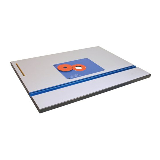
Precision router table top
Hide thumbs
Also See for PRS1020:
- Assembly instructions manual (24 pages) ,
- Assembly instructions manual (24 pages)
Table of Contents
Advertisement
Quick Links
Advertisement
Table of Contents

Related Manuals for Kreg PRS1020


Summary of Contents for Kreg PRS1020
- Page 1 Precision Router Table Top ( 24” x 32” ) ASSEMBLY INSTRUCTIONS Item# PRS1020 Tools Required: • 5/64” Allen Wrench • Phillips Head Screwdriver • Flat Head Screwdriver • 6” #2 Square Driver • 1/8” Allen Wrench (Included) • 3” #2 Square Driver (Included) www.kregtool.com •...
- Page 2 Step 2: Mounting the Support Struts to the Table Top Turn the Router Table top (#2) so it’s face down on the fl oor. Locate the two Support Struts (#7) and align them to the pre-drilled holes in the bottom of the Router Table Top.
- Page 3 Insert Plate so that you can connect your router directly to the Insert Plate. First, you must determine the correct size of the holes to drill in your Insert Plate. Remove the base plate from your router and fi nd the bit that fi ts just inside of the base plate’s holes.
- Page 4 Precision Router Table Top Exploded Parts Diagram Slot to attach Kreg Precision Router Table Fence. Hardware Item# Description Phenolic Insert Plate Table Top T-Miter Track 2” Reducing Ring 1-13/64” Reducing Ring Brass Starting Pin Support Strut Insert Plate Leveler 1/4-20 x 3/4” Set Screw 1/4-20 x 1-1/2”...
- Page 5 Adjust the Insert Plate as close as possible to fl ush with the surface of the router table top and run your fi nger along the perimeter of the Insert Plate to check that all edges are fl ush with the router table top.
- Page 6 The starting pin included with your router table is useful when routing curves. It supports the edge of your work piece and allows you to gently ease your work into the router bit. It should only be used with router bits that have a bearing.
- Page 7 NOT be modifi ed and/or used for any application other than for which it was designed. If you have any questions relative to its application, DO NOT use the tool until you have written, phoned, or e-mailed Kreg Tool and have been advised accordingly.
- Page 8 Precision Router Table Fence ASSEMBLY INSTRUCTIONS Item# PRS1010 Tools Required: • 7/16” Open Ended Wrench • Flat Head Screwdriver • Phillips Head Screwdriver www.kregtool.com • 800.447.8638 Version 20070701 RT10142...
- Page 9 NOT be modifi ed and/or used for any application other than for which it was designed. If you have any questions relative to its application, DO NOT use the tool until you have written, phoned, or e-mailed Kreg Tool and have been advised accordingly.
- Page 10 Table Mount -- making sure the top edge of the Clamp Block (#2) is fl ush or 1/32” below the surface of your router table top and that the Clamp Block and Mounting Rail (#1) run perfectly parallel to the edge of the table top.
- Page 11 Precision Router Table Fence Parts Explosion Hardware Description MOUNTING RAIL CLAMP BLOCK ASSEMBLY FENCE MOUNT LARGE FENCE TABLE MOUNT FENCE FACE FENCE END CAP 8” ALUMINUM TAPE SLIDER 8” SCALE PRECISION LENS CURSOR FENCE GUARD RIGHT ANGLE BRACKET EXTENSION KNOB ASSEMBLY DUST PORT 16”...
- Page 12 Nut. Before tightening the nut, align the Right Angle Bracket over the 6” slot on the left side of the Kreg Router Table Top. Place the Brass T-Nut (#30) through the slot from the underside of the Router Table Top and attach the Extension Knob Asembly (#13) by putting it through the Right Angle Bracket and threading it into the Brass T-Nut.
- Page 13 Washers (#17) and two Small T-Knobs (#16). Step 15 Slide the fence to the back of the router table top. Locate the 8 ¼” Tape Slider (#8). Insert the Tape Slider into the Mounting Rail (#1) and thread the Knurled Thumb Screw (#19) from the bottom side of the Mounting Rail to hold the Tape Slider in place.
- Page 14 Precision Lens Cursor. In-Use: Jointing The Kreg Precision Router Table Fence features fully independent fence faces which allow the fence to double as a vertical jointer. To set up the jointer, begin by loosening the out-feed face -- being careful not to go to far and disconnect the screw from the Jam Nut -- and removing the two Jointing Rods (#15) which are stored in the back of the fence, as shown.
- Page 15 Parts Identifi cation: Legs (4) Short Stretcher (4) Long Stretcher (4) Universal Steel Stand ASSEMBLY INSTRUCTIONS Tools Required: • Square • 1/2” Socket wrench & extension • (2) 3/4” Open-end or adjustable wrenches • Phillips head driver bit www.kregtool.com • 800.447.8638 Please call us at 800-447-8638 with any questions regarding the assembly of this stand.
- Page 16 Step 1 Constructing Side Assemblies: In this step you will be joining four (4) Long Stretchers and four (4) Legs to construct two separate side-assemblies. Special Note: One of your Long Stretchers includes a Kreg logo. You may choose where you would like this stretcher to be positioned. Begin by laying two (2) Legs fl...
- Page 17 Step 3 Installing Height adjusters: In this step you will be adding the Height Adjusters to the bottom of each Leg. Place the Steel Stand face-down on your work surface so that all four legs are pointed up in the air, and are easily accessible, as shown in image A. Place the height adjuster into the base of the Leg, with the squared end at the bottom of the stand, as shown in image B.
- Page 18 Step 5 Joining Table Top to Stand: In this step you will be joining the Universal Steel Stand to a Kreg or other table-top of your choice. Place the table face-down on your work surface, and have someone help you fl ip the stand on top of it, as shown in image A.
Need help?
Do you have a question about the PRS1020 and is the answer not in the manual?
Questions and answers