
Related Manuals for Syscom Video DSP COLOR CAMERA

Summary of Contents for Syscom Video DSP COLOR CAMERA
- Page 1 INSTRUCTION MANUAL DSP COLOR CAMERA 1/3" INTERLINE TRANSFER CCD STANDARD RESOLUTION HIGH RESOLUTION Please read this manual thoroughly before use, and keep it handy for future reference.
- Page 2 ISSUE 1 – MAY 2001...
- Page 3 WARNINGS AND CAUTIONS TO REDUCE THE RISK OF FIRE OR ELECTRIC SHOCK, DO NOT EXPOSE THIS PRODUCT TO RAIN OR MOISTURE. DO NOT INSERT ANY METALLIC OBJECTS THROUGH THE VENTILATION GRILLS OR OTHER OPENINGS ON THE EQUIPMENT. CAUTION EXPLANATION OF GRAPHICAL SYMBOLS The lightning flash with arrowhead symbol, within an equilateral triangle, is intended to alert the user to the presence of uninsulated “dangerous voltage”...
- Page 4 FCC COMPLIANCE STATEMENT INFORMATION TO THE USER: THIS EQUIPMENT HAS BEEN TESTED AND FOUND TO COMPLY WITH THE LIMITS FOR A CLASS B DIGITAL DEVICE, PURSUANT TO PART 15 OF THE FCC RULES. THESE LIMITS ARE DESIGNED TO PROVIDE REASONABLE PROTECTION AGAINST HARMFUL INTERFERENCE IN A RESIDENTIAL INSTALLATION.
- Page 5 IMPORTANT SAFEGUARDS 1. READ AND RETAIN INSTRUCTIONS than the other) will fit into the power outlet only Read the instruction manual before operating one way. This is a safety feature. If you are the equipment. Retain the manual for future unable to insert the plug fully into the outlet, try reference.
- Page 6 13. DAMAGE REQUIRING SERVICE 14. REPLACEMENT PARTS Unplug the equipment from the wall outlet When replacement parts are required, be and refer servicing to qualified service sure the service technician uses personnel under the following conditions: replacement parts specified by the manufacturer or that have the same When the power supply cord or the characteristics as the original part.
-
Page 7: Table Of Contents
TABLE OF CONTENTS INTRODUCTION ................. 1 CAMERA OVERVIEW ................ 2 CONTENTS OF PACKAGE ..............6 BASIC INSTALLATION................. 6 MANUAL IRIS LENS ADJUSTMENT ............ 9 VIDEO-TYPE AUTO-IRIS LENS INSTALLATION AND ADJUSTMENT ................9 DC-TYPE AUTO-IRIS LENS INSTALLATION AND ADJUSTMENT ................11 BACKFOCUS ADJUSTMENT ..............12 ZOOM LENS BACKFOCUS ADJUSTMENT ........13 TROUBLESHOOTING .................14 PREVENTIVE MAINTENANCE............15... - Page 8 THIS PAGE INTENTIONALLY LEFT BLANK. viii...
-
Page 9: Introduction
ABOUT THE 1/3" DSP COLOR CAMERA INTRODUCTION The 1/3" DSP color security camera provides SONY, true-color images especially for closed-circuit television (CCTV) and security surveillance applications. Features: • High-performance 1/3" SONY DSP color CCD technology • 330 lines of resolution (Standard);... -
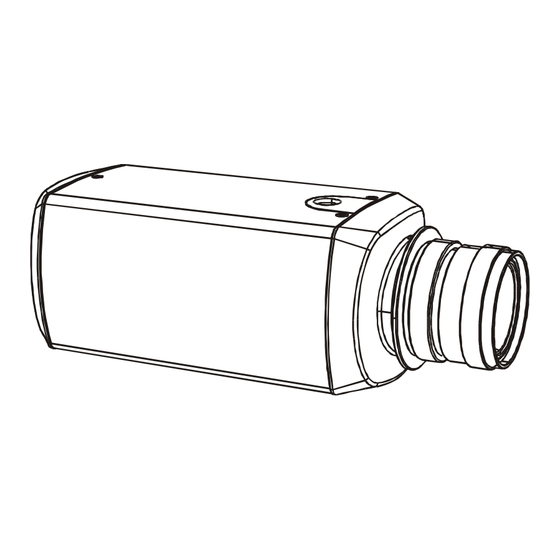
Page 10: Camera Overview
CAMERA OVERVIEW SIDE VIEW C Mount Ring Back Focus Lock Screw ( C MOUNT LENS ) ( CS MOUNT LENS ) Camera Mounting Bracket Back Focus Ring BACK VIEW (12V DC) Power LED Level potentiometer LENS (for DC type A/I lens) LEVEL Auto Iris Lens Connector... - Page 11 Back focus Lock Screw – Allows the user to secure the backfocus setting. C/CS Back focus Adjust Ring – Allows the user to adjust the back focal length or picture focus by rotating this ring clockwise for C-mount and counter-clockwise for CS-mount lenses. Mounting Bracket Hole –...
- Page 12 SHTR Switch (Aes/Mes) – This switch allows the user to choose • between auto exposure and manual exposure. Position the switch toward the front of the camera for auto exposure, whereby the exposure is performed by the electronic iris and AGC control. Position the switch toward the back of the camera for manual exposure, whereby the shutter speed can be set by the shutter adjust.
- Page 13 • Gamma Switch (on/off) – The gamma correction switch allows .45 correction for non-linearity gain response in the monitor when set to When set to OFF, there is no gamma correction. • AGC Switch (off/on) – The auto gain control switch allows the video signals to maintain a constant level.
-
Page 14: Contents Of Package
CONTENTS OF PACKAGE Installation of the camera must be performed by qualified service personnel in accordance with all local and national electrical and mechanical codes. Carefully remove the color camera and its accessories from the carton and verify that they were not damaged in shipment. The contents of the package includes: Color CCD camera Mini-DIN connector (for video- or dc-type auto-iris lens) - Page 15 IMPORTANT: The minimum recommended load rating for the mounting bracket is 11 lbs (5Kg). The observation camera has a ¼"-20 UNC mounting holes located at the top and the bottom of the camera housing to allow for top or bottom mounting.
- Page 16 Plug the other end of the cable into the corresponding camera input port on the back of the observation monitor. On 12V DC models : 10. Connect a 2-conductor power cable to the 12V DC input port located on the back of the camera. 12V DC Class 2 Use a UL-listed Class 2 power transformer and a 12V DC power...
-
Page 17: Manual Iris Lens Adjustment
MANUAL IRIS LENS ADJUSTMENT A manual iris lens is used in indoor applications where lighting from windows can considerably affect the light level of the room. When using the manual iris lens, perform the following: Set the E/I switch to ON. Turn the iris ring on the lens to the fully OPEN position. - Page 18 Open Voltage + / Red Video / White Ground / Black Plug the connector into the auto-iris lens jack on the top of the camera. The connector is keyed and can only be inserted into the jack one way. Make sure that the E/I switch located on the back of the camera is set to OFF and the A/I switch is set to Video.
-
Page 19: Dc-Type Auto-Iris Lens Installation
Set the backfocus of the camera before the final adjustment of the video level. See section 3.6 for further instructions. If the auto-iris has a gain adjustment: • If the lens oscillates between open and closed under bright lights, slowly turn the gain adjustment counter-clockwise until the oscillating stops. -
Page 20: Backfocus Adjustment
BACKFOCUS ADJUSTMENT Although the camera lens was backfocused by the manufacturer prior to shipping, it may be necessary to make modifications. For best results, perform backfocus adjustments at night or while using a #6 or #8 welder’s glass in front of the lens. The focus of the camera will change slightly if the camera iris was adjusted on a light scene and then changes to a dark scene. -
Page 21: Zoom Lens Backfocus Adjustment
ZOOM LENS BACKFOCUS ADJUSTMENT The objective of backfocusing a zoom lens is similar to that of a fixed focal length camera, except that the backfocus is also adjusted to maintain the focus when “zooming” the lens in and out of a scene. For zoom lens backfocus adjustment, perform the following: Choose an object at the farthest range that you wish to look at with a zoom lens. -
Page 22: Troubleshooting
TROUBLESHOOTING If problems occur, verify the installation of the camera with the instructions in this manual and with other operating equipment. Isolate the problem to the specific piece of equipment in the system and refer to the equipment manual for further information. PROBLEM CHECK Make sure the system is plugged in. -
Page 23: Preventive Maintenance
PREVENTIVE MAINTENANCE Following the preventive maintenance schedule allows detection and correction of minor faults before they become serious and cause equipment failure. Every three months, perform the following: Inspect all connecting cables for deterioration or other damage. Clean components with a clean damp cloth. Verify that all mounting hardware is secure. -
Page 24: Spcifications
SPECIFICATIONS * Standard Resolution DSP Color Camera * Power Power Source, Consumption : 12VDC +/-20% Max. 5.0 Watts. Power Indicator : Green LED Sensor Information and General Processing Technology : Sony DSP Image Sensor : 1/3" interline transfer CCD (sony chip... - Page 25 Function Auto/Man Shutter Control(E.S.) : Auto(On), Man(Off) (Dip Switch) Manual Shutter Control : 1/60(1/50), 1/100(1/120), 1/250, 1/500, 1/1000, 1/2000, 1/4000, 1/10,000(Dip Switch) Flickerless(F.F) : ON/OFF (Dip Switch) BLC : ON/OFF (Dip Switch) EI : ON/OFF (Dip Switch) Auto Iris Lens : DC/Video (Dip Switch) Gamma(γ) : ON/OFF (Dip Switch)
- Page 26 * High Resolution DSP Color Camera * Power Power Source, Consumption : 12VDC +/-20% Max. 5.0 Watts. Power Indicator : Green LED Sensor Information and General Processing Technology : Sony DSP Image Sensor : 1/3" interline transfer CCD (sony chip set)
- Page 27 Function Auto/Man Shutter Control(E.S.) : Auto(On), Man(Off) (Dip Switch) Manual Shutter Control : 1/60(1/50), 1/100(1/120), 1/250, 1/500, 1/1000, 1/2000, 1/4000, 1/10,000(Dip Switch) Flickerless(F.F) : ON/OFF (Dip Switch) BLC : ON/OFF (Dip Switch) EI : ON/OFF (Dip Switch) Auto Iris Lens : DC/Video (Dip Switch) Gamma(γ) : ON/OFF (Dip Switch)
- Page 28 DSP COLOR CAMERA 1/3” INTERLINE TRANSFER CCD STANDARD RESOLUTION HIGH RESOLUTION 50301421A...
Need help?
Do you have a question about the DSP COLOR CAMERA and is the answer not in the manual?
Questions and answers