Toshiba Satellite C800 Maintenance Manual
Hide thumbs
Also See for Satellite C800:
- Manual del usuario (209 pages) ,
- User manual (190 pages) ,
- Manual del usuario (206 pages)
Chapters
Table of Contents
Troubleshooting

Related Manuals for Toshiba Satellite C800


Summary of Contents for Toshiba Satellite C800
- Page 1 Toshiba Personal Computer Satellite C800 and Satellite L800 Maintenance Manual (960-Q08) Maintenance Manual TOSHIBA CORPORATION File Number 960-Q08 Satellite C800 and Satellite L800 Maintenance Manual (960-Q08)
- Page 2 © 2010 by Toshiba Corporation. All rights reserved. Under the copyright laws, this manual cannot be reproduced in any form without the prior written permission of Toshiba. No patent liability is assumed with respect to the use of the information contained herein.
- Page 3 NOTE: “Note” contains general information that relates to your safe maintenance service. Improper repair of the computer may result in safety hazards. Toshiba requires service technicians and authorized dealers or service providers to ensure the following safety precautions are adhered to strictly.
- Page 4 Replacement Procedures describes the removal and replacement of the FRUs. Appendices The appendices describe the following: Handling the LCD Module Board layout Pin assignments Keyboard scan/character code Key layout Wiring diagrams Satellite C800 and Satellite L800 Maintenance Manual (960-Q08)
- Page 5 Text that you are instructed to type in is shown in the boldface type below: DISKCOPY A: B: The display Text generated by the computer that appears on its display is presented in the typeface below: Format complete System transferred Satellite C800 and Satellite L800 Maintenance Manual (960-Q08)
-
Page 6: Table Of Contents
TFT Color Display .......................23 1.6.1 LCD Module With CCFL Backlight ............23 Power Supply .......................25 Batteries ........................26 1.8.1 Main Battery .....................26 1.8.2 Battery Charging Control ................27 1.8.3 RTC battery ....................28 AC Adapter ........................29 Satellite C800 and Satellite L800 Maintenance Manual (960-Q08) - Page 7 Diagnostic Test Program Execution Check ......26 Procedure 2 Connector Check and Replacement Check ......27 Display Troubleshooting ..................... 28 Procedure 1 External Monitor Check ............28 Procedure 2 Diagnostic Test Program Execution Check ......28 Satellite C800 and Satellite L800 Maintenance Manual (960-Q08)
- Page 8 Antennas' Connection Check ...........38 Procedure 3 Replacement Check ..............39 2.14 Sound Troubleshooting ....................40 Procedure 1 Connector Check ..............40 Procedure 2 Replacement Check ..............41 2.15 Fingerprint Troubleshooting ..................42 Procedure 1 Diagnostic Test Program Execution Check ......42 Satellite C800 and Satellite L800 Maintenance Manual (960-Q08)
- Page 9 3.21 Common Tests and Operation ..................63 3.21.1How to operate a window ................63 3.21.2How to Stop the Test Program ..............63 3.21.3Test Status Screen ..................63 3.21.4Test Stop Display ..................65 Satellite C800 and Satellite L800 Maintenance Manual (960-Q08)
- Page 10 System Board .......................34 4.12 CPU ..........................37 4.13 LCD unit ........................40 4.14 Web Camera module ....................44 4.15 Speaker Box .........................45 4.16 Use thermal pad and grease on CPU, North Bridge, and VGA Board ......47 Satellite C800 and Satellite L800 Maintenance Manual (960-Q08)
- Page 11 Handling the LCD Module ................1 Appendix B Board Layout ..................... 1 Appendix C Pin Assignments ....................1 Appendix D Keyboard Scan/Character Codes ............... 1 Appendix E Key Layout ......................1 Appendix F Wiring Diagrams ....................1 Satellite C800 and Satellite L800 Maintenance Manual (960-Q08)
- Page 12 Chapter 1 Hardware Overview Satellite C800 and Satellite L800 Maintenance Manual (960-Q08)
- Page 13 TFT Color Display .......................23 1.6.1 LCD Module With CCFL Backlight ............23 Power Supply .......................25 Batteries ........................26 1.8.1 Main Battery ...................26 1.8.2 Battery Charging Control ...............27 1.8.3 RTC battery ....................28 AC Adapter ........................29 Satellite C800 and Satellite L800 Maintenance Manual (960-Q08)
- Page 14 Table 1-13 Time required for charges of main battery ............27 Table 1-14 Data preservation time ..................27 Table 1-15 Time required for charges of RTC battery ............28 Table 1-16 AC adapter specifications ................29 Satellite C800 and Satellite L800 Maintenance Manual (960-Q08)
- Page 15 Chapter 1 Hardware Overview Satellite C800 and Satellite L800 Maintenance Manual (960-Q08)
-
Page 16: Features
Chapter 1 Hardware Overview 1.1 Features The Satellite C800/C845/L800/L840/L845 (Intel Platform) features are listed below. Microprocessor Microprocessor that is used will be different by the model. It supports processors as follows 1. Intel® Sandy Bridge Processor CPU (988P) I3-2350M 2.3G CPU (988P) I5-2410M 2.3G... - Page 17 The main battery is a detachable lithium ion battery. 3cell Li-Ion 2200mAh 6 cell Li-Ion 4400mAh 6 cell Li-Ion(high capacity) 6000mAh USB (Universal Serial Bus) 3 USB ports are provided. USB 3.0 port is supported depend on SKU. Satellite C800 and Satellite L800 Maintenance Manual (960-Q08)
- Page 18 Bluetooth & WLAN Bluetooth is combo module with WLAN. 3G GPS function is supported by 3G/LTE module. Security 2 level boot pass word by BIOS setup menu & TOSHIBA password utility. Satellite C800 and Satellite L800 Maintenance Manual (960-Q08)
-
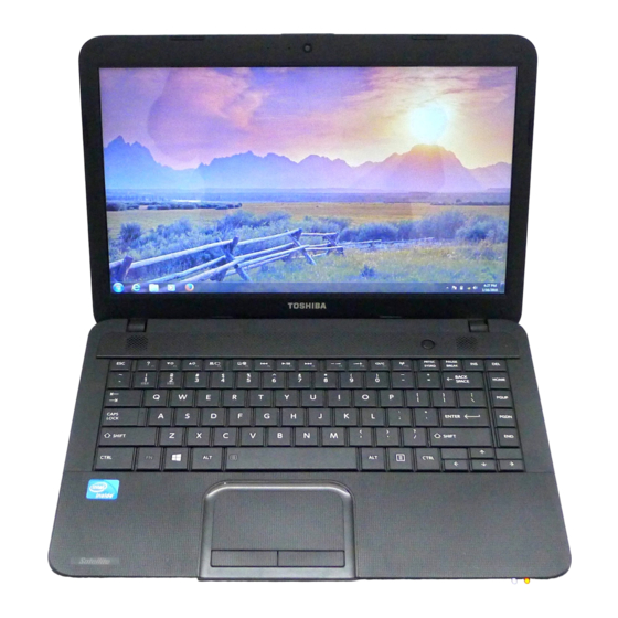
Page 19: Figure 1-1 Front Of The Computer
Chapter 1 Hardware Overview Figure 1-1 Front of the computer Satellite C800 and Satellite L800 Maintenance Manual (960-Q08) -
Page 20: System Block Diagram
Chapter 1 Hardware Overview 1.2 System Block Diagram Figure 1-2 shows the system block diagram. Figure 1-2 System block diagram for Intel Platform Satellite C800 and Satellite L800 Maintenance Manual (960-Q08) - Page 21 Two memory slots capable of accepting DDRIII-SDRAM,1GB, 2GB, 4GB or 8GB memory modules for a maximum of 8GB. 204-pin SO-DIMM 1.5V operation BIOS ROM (Flash memory) 32Mbit Chipset (Chief River Platform) Satellite C800 and Satellite L800 Maintenance Manual (960-Q08)
- Page 22 JTAG Boundary-Scan Integrated Clock Controller SOL Function KVM IDE-R Function Other main system chips • EC/KBC (Nuvoton NPCE885LA0DX) • HD Audio (Conexant CX20671-21Z) • Card Reader controller (Alcor AU6437) Satellite C800 and Satellite L800 Maintenance Manual (960-Q08)
- Page 23 • Gigabit 10/100/1000M LAN controller (Atheros AR8151) Mini Card Wireless LAN card Support module type: 11a/b/g/n, 11b/g/n, 11ac/a/b/g/n 3G/LTE card PS support and SIM card design ready. Bluetooth Combo module with WLAN. Satellite C800 and Satellite L800 Maintenance Manual (960-Q08)
-
Page 24: Inch Hard Disk Drive
Height (mm) dimens Depth (mm) 100.45 +/- 0.25 ions Weight (g) Parameter Standard value Toshiba(320GB Toshiba(500GB Toshiba(640GB Toshiba(750GB )MK3275GSX )MK5075GSX )MK6475GSX )MK7575GSX Width (mm) 69.85 Outline Height (mm) dimensi Depth (mm) Weight (g) Satellite C800 and Satellite L800 Maintenance Manual (960-Q08) -
Page 25: Table 1-2 2.5-Inch Hdd Dimensions
Standard value Hitachi 7mm 250G Hitachi 7mm 320G Hitachi 7mm 500G HTS545025A7E380 HTS545032A7E380 HTS545050A7E380 Width 69.85 +/- 0.25 (mm) Outline Height 6.8 +/- 0.2 dimensi (mm) Depth 100.2 +/- 0.25 (mm) 95(Max) Weight Satellite C800 and Satellite L800 Maintenance Manual (960-Q08) -
Page 26: Table 1-3 2.5-Inch Hdd Specifications
640GB 750GB (formatted) Speed (RPM) 5,400 Data transfer Rate 584.3~1195.5 (Mbits/sec) - To/From Media 3(Gbits/sec) - To/From Host bus transfer rate 1.5Gbps(150MB/s) (MB/s) Average random seek time (read) (ms) Power-on-to-ready 3.5(typ)/9.5(Max) (sec) Satellite C800 and Satellite L800 Maintenance Manual (960-Q08) -
Page 27: Table 1-3 2.5-Inch Hdd Specifications
1004(Mbits/sec) Max. 897(Mbits/sec) Max. 1004(Mbits/sec) Max. - To/From Media 3(Gbits/sec) 3(Gbits/sec) 3(Gbits/sec) - To/From Host bus transfer rate 1.5Gbps (150MB/s) (MB/s) Average random seek 13 (typ) time (read) (ms) Power-on-to-ready 3.5 (typ) (sec) Satellite C800 and Satellite L800 Maintenance Manual (960-Q08) -
Page 28: Optical Drive
The DVD Super Multi drive is shown in Figure 1-4. The dimensions and specifications of the DVD Super Multi drive are described in Table 1-3, Table 1-4, Table 1-5, Table 1-6, Table 1- Figure 1-4 DVD Super Multi drive Satellite C800 and Satellite L800 Maintenance Manual (960-Q08) -
Page 29: Table 1-4 Dvd Super Multi Drive Outline Dimensions
(SN-208AB/TOJF) Width (mm) Outline Height (mm) 12.7 dimensions Depth (mm) Mass (g) Parameter 12.7 mm Bule Ray ODD HLDS Maker (BT20N.ATAK1N1) Width (mm) Outline Height (mm) 12.7 dimensions Depth (mm) Mass (g) Satellite C800 and Satellite L800 Maintenance Manual (960-Q08) -
Page 30: Table 1-4 Dvd Super Multi Drive Outline Dimensions
Chapter 1 Hardware Overview Parameter 12.7 mm Bule Ray ODD TSST TSST Maker (SN-506AB/TFNF) (TS-LB23D/TFJN) Width (mm) Outline Height (mm) 12.7 dimensions Depth (mm) Mass (g) Satellite C800 and Satellite L800 Maintenance Manual (960-Q08) -
Page 31: Table 1-5 Pcc Dvd Super Multi Drive Specifications
Max.3.3x-6X PCAV DVD+RW : Max.8X Zone CLV DVD-RAM : Max.3-5X PCAV (4.7GB) Burst Transfer SATA Gen.1 1.5 G bps (150MB/s) mode 150ms (Typ.) Access time (ms) DVD- 180ms (Typ.) (Random) Buffer memory Satellite C800 and Satellite L800 Maintenance Manual (960-Q08) -
Page 32: Table 1-6 Hlds Dvd Super Multi Drive Specifications
4x, 10x CLV, 16x ZCLV, 24x ZCLV(High Speed: 10x CLV, Ultra Speed: 24x ZCLV) Burst Transfer SATA Gen.1 1.5 G bps (150MB/s) mode 140ms (Typ.) Access time DVD- 160ms (Typ.) (ms) (Random) DVD- 260ms (Typ.) Buffer memory Satellite C800 and Satellite L800 Maintenance Manual (960-Q08) -
Page 33: Table 1-7 Tsst Dvd Super Multi Drive Specifications
200 ms (Typ) 230 ms (Max) (ms) DVD±R/RW 190 ms (Typ) 220 ms (Max) (Random) DVD±R Dual 200 ms (Typ) 230 ms (Max) DVD-RAM 250 ms (Typ) 350 ms (Max) Buffer memory Satellite C800 and Satellite L800 Maintenance Manual (960-Q08) -
Page 34: Table 1-8 Hlds Slim Blu-Ray Odd Specifications
4x, 10x CLV, 16x ZCLV Burst Transfer SATA Gen.1 150MB/s mode BD-ROM 230 ms typ. Access time DVD-ROM 200 ms typ. (ms) DVD-RAM (Ver.2.2) 210 ms typ. (Random) CD-ROM 200 ms typ. Buffer memory Satellite C800 and Satellite L800 Maintenance Manual (960-Q08) -
Page 35: Table 1-8 Hlds Slim Blu-Ray Odd Specifications
4x, 10x CLV, 16x ZCLV Burst Transfer SATA Gen.1 150MB/s mode BD-ROM 230 ms typ. Access time DVD-ROM 200 ms typ. (ms) DVD-RAM (Ver.2.2) 210 ms typ. (Random) CD-ROM 200 ms typ. Buffer memory Satellite C800 and Satellite L800 Maintenance Manual (960-Q08) -
Page 36: Keyboard
Figure 1-5 is a view of the keyboard for US style Figure 1-5 Keyboard for US style Figure 1-6 is a view of the keyboard for UK style Figure 1-6 Keyboards for UK style Satellite C800 and Satellite L800 Maintenance Manual (960-Q08) -
Page 37: Figure 1-7 Keyboard For Japan Style
Chapter 1 Hardware Overview Figure 1-7 is a view of the keyboard for JAPAN style Figure 1-7 Keyboard for JAPAN style Satellite C800 and Satellite L800 Maintenance Manual (960-Q08) -
Page 38: Tft Color Display
40 pins LVDS interface. This module supports 1366 x 768 HD mode and can display 262,144 colors. 1.6.1 LCD Module with LED Backlight Figure 1-8 shows a view of the LCD module and Table 1-9 lists the specifications. Figure 1-8 CHIMEI LCD Module Satellite C800 and Satellite L800 Maintenance Manual (960-Q08) -
Page 39: Table 1-9 Led Module Specifications
1366 x 768 1366 x 768 1366 x 768 0.2265 0.2265 0.2265 Dot spacing (mm) 0.2265 (H)x0.2265 (V) (H)x0.2265 (V) (H)x0.2265 (V) (H)x0.2265 (V) Display Colors 262,144 colors 262,144 colors 262,144 colors 262,144 colors Satellite C800 and Satellite L800 Maintenance Manual (960-Q08) -
Page 40: Power Supply
Power supply (Yes/No) Name Power OFF Power OFF Voltage [V] No Battery Suspend mode Boot mode +5VPCU +3VPCU +3V_S5 +3VSUS +1.8VSUS +SMDDR_VTERM +SMDDR_VREF +1.8V +1.5V +1.2V 1.25 +1.05v 1.05 +NB_CORE 1.0~1.2 VCC_CORE 0.7~1.2 Satellite C800 and Satellite L800 Maintenance Manual (960-Q08) -
Page 41: Batteries
1.8.1 Main Battery The main battery is the primary power supply for the computer when the AC adapter is not connected. In Standby, the main battery maintains the current status of the computer. Satellite C800 and Satellite L800 Maintenance Manual (960-Q08) -
Page 42: Battery Charging Control
Standby About 3 days Hibernation About 1 month 6 cell Approximately 3 days(sleep mode) Battery Pack 3 cell Approximately 1.5 days(sleep mode) Approximately 1 month(shutdown mode,All type of battery pack Satellite C800 and Satellite L800 Maintenance Manual (960-Q08) -
Page 43: Rtc Battery
Table 1-15 lists the Time required for charges of RTC battery and data preservation time. Table 1-15 Time required for charges of RTC battery Condition Time Power ON (Lights Power LED) About 24 hours Data preservation tome (Full-charged) About a month Satellite C800 and Satellite L800 Maintenance Manual (960-Q08) -
Page 44: Ac Adapter
Table 1-16 AC adapter specifications Parameter Specification Chiony/ DELTA/ LITE- DELTA/ LITE- DELTA/ With Led LITE-ON Power Input voltage AC 100V/240V Input frequency 50Hz~60Hz ≦1.5A Input current Output voltage DC 19V Output current 3.42A 3.95A 4.74A Satellite C800 and Satellite L800 Maintenance Manual (960-Q08) -
Page 45: Chapter 2 Troubleshooting Procedures
Chapter 2 Troubleshooting Procedures Satellite C800 and Satellite L800 Maintenance Manual (960-Q08) - Page 46 Diagnostic Test Program Execution Check ......24 Procedure 2 Connector Check and Replacement Check ......25 Touch pad Troubleshooting ..................26 Procedure 1 Diagnostic Test Program Execution Check ......26 Procedure 2 Connector Check and Replacement Check ......27 2-2 Satellite C800 and Satellite L800 Maintenance Manual (960-Q08)
- Page 47 Antennas' Connection Check ...........38 Procedure 3 Replacement Check ..............39 2.14 Sound Troubleshooting ....................40 Procedure 1 Connector Check ..............40 Procedure 2 Replacement Check ..............41 2.15 Fingerprint Troubleshooting ..................42 Procedure 1 Diagnostic Test Program Execution Check ......42 Satellite C800 and Satellite L800 Maintenance Manual (960-Q08)
-
Page 48: Troubleshooting
The implement for the Diagnostics procedures is referred to Chapter 3. Also, following implements are necessary: 1. Phillips screwdrivers (For replacement procedures) 2. Implements for debugging port check Toshiba Free-DOS system FD Satellite C800 and Satellite L800 Maintenance Manual (960-Q08) -
Page 49: Procedure
2.3 Power Supply Troubleshooting. (1) Cable connection is described in the figure as line. (2) Pin connection is described in the figure as arrow. <e.g.> Connection of modem RJ11 CONN Phone Cable Modem Module Satellite C800 and Satellite L800 Maintenance Manual (960-Q08) -
Page 50: Troubleshooting Flowchart
Before going through the flowchart steps, verify the following: Ask customer to enter the password if a password is registered. Verify with the customer that Toshiba Windows is installed on the hard disk. Non- Windows operating systems can cause the computer to malfunction. - Page 51 2 Troubleshooting Procedures Figure 2-1 Troubleshooting flowchart (1/2) Satellite C800 and Satellite L800 Maintenance Manual (960-Q08)
-
Page 52: Procedure
2 Troubleshooting Procedures Figure 2-1 Troubleshooting flowchart (2/2) Satellite C800 and Satellite L800 Maintenance Manual (960-Q08) - Page 53 12. If an error is detected on the fingerprint test, perform the fingerprint Troubleshooting Procedures in Section 2.15. 13. If an error is detected on the Bluetooth test, perform the Bluetooth Troubleshooting Procedures in Section 2.16. Satellite C800 and Satellite L800 Maintenance Manual (960-Q08)
-
Page 54: Power Supply Troubleshooting
The battery level is low while the system power is ON. (even intervals) Blinks orange once The system is driven by only a battery and the battery level (at being switched on) is low. Doesn’t light Any condition other than those above. Satellite C800 and Satellite L800 Maintenance Manual (960-Q08) -
Page 55: Battery Pack
Check 2 If the DC IN icon does not light, go to Procedure 3. Check 3 If the battery icon does not light orange or green, go to Procedure 4. NOTE: Use a supplied AC adapter. Satellite C800 and Satellite L800 Maintenance Manual (960-Q08) -
Page 56: Procedure 2 Connection Check
The battery’s temperature is too high or low. Leave the battery for a while to Check 4 adjust it in the right temperature. If the battery pack is still not charged, go to Satellite C800 and Satellite L800 Maintenance Manual (960-Q08) - Page 57 2 Troubleshooting Procedures Check 5. Check 5 Replace the battery pack with a new one. If the battery pack is still not charged, go to Procedure 4. Satellite C800 and Satellite L800 Maintenance Manual (960-Q08)
-
Page 58: Procedure 4 Replacement Check
Battery pack may be faulty. Replace it with a new one. If the problem still occurs, perform Check 2. Check 2 System board may be faulty. Replace it with a new one. Satellite C800 and Satellite L800 Maintenance Manual (960-Q08) -
Page 59: System Board Troubleshooting
Procedure 1 and continue with the other procedures as instructed. The procedures described in this section are: Procedure 1: Message Check Procedure 2: Diagnostic Test Program Execution Check Procedure 3: Replacement Check Satellite C800 and Satellite L800 Maintenance Manual (960-Q08) -
Page 60: Procedure 1 Message Check
If you press the F2 key as the message instructs, the SETUP screen appears to set the system configuration. If error message (b) appears often when the power is turned on, replace the RTC battery. Satellite C800 and Satellite L800 Maintenance Manual (960-Q08) -
Page 61: Procedure 2
If an error is detected during these tests, go to Procedure 3. Procedure 3 Replacement Check System board may be faulty. Disassemble the computer following the steps described in Chapter 4, Replacement Procedures and replace system board with a new one. Satellite C800 and Satellite L800 Maintenance Manual (960-Q08) -
Page 62: Usb Fdd Troubleshooting
Procedure 2. Detailed operation is given in Chapter 3, Tests and Diagnostics. If the test program cannot be executed on the computer, go to Procedure 3. Satellite C800 and Satellite L800 Maintenance Manual (960-Q08) -
Page 63: Diagnostic Test Program Execution Check
“write enable”. If any other message appears, perform Check 2. Write protected Check 2 Make sure the floppy disk is formatted correctly. If it is, go to Procedure 3. Satellite C800 and Satellite L800 Maintenance Manual (960-Q08) -
Page 64: Procedure 3 Connector Check And Replacement Check
1. Cable can not be disconnected from the connector. 2. Cable is connected straight to the connector. 3. Cable is connected all the way seated in the connector. 4. Cable can not be broken. Satellite C800 and Satellite L800 Maintenance Manual (960-Q08) - Page 65 If it does not work properly when connected to CN12, CN19, CN20 or all ports, perform Check 4. Check 4 System board may be faulty. Replace it with a new one following the steps in Chapter 4, Replacement Procedures. Satellite C800 and Satellite L800 Maintenance Manual (960-Q08)
-
Page 66: Hdd Troubleshooting
User’s Manual. Procedure 1 Partition Check Insert the Toshiba MS-DOS system disk and start the computer. Perform the following checks: Check 1 Input C: and press Enter. If you cannot change to drive C, go to Check 2. If you can change to drive C, go to Procedure 2. - Page 67 2.5” HDD(s) and the connector(s) of system board may be defective (Refer to the steps described in Chapter 4, Replacement Procedures for disassembling.). Insert HDD(s) to the connector(s) firmly. If it is (or they are) firmly connected, go to Procedure 3. Satellite C800 and Satellite L800 Maintenance Manual (960-Q08)
- Page 68 Using the Diagnostic Disk, format 2.5” HDD with a format option (physical format). If HDD is formatted, set the 2.5” HDD partition using Free -DOS FDISK command. If you cannot format 2.5” HDD using the Tests and Diagnostic program, go to Procedure 4. Satellite C800 and Satellite L800 Maintenance Manual (960-Q08)
- Page 69 Table 2-8. If an error code is not displayed but the problem still occurs, go to Procedure 5. Table 2-8 2.5” Hard disk drive error code and status Satellite C800 and Satellite L800 Maintenance Manual (960-Q08)
- Page 70 Chapter 4, Replacement Procedures and check the operation. If the problem still occurs, perform Check 3. Check 3 System board may be faulty. Replace it with a new one following the instructions in Chapter 4, Replacement Procedures. Satellite C800 and Satellite L800 Maintenance Manual (960-Q08)
-
Page 71: Procedure 5 Connector Check And Replacement Check
ONE TEST) in the Diagnostic Program. Refer to Chapter 3, Tests and Diagnostics, for more information on how to perform the test program. If an error occurs, go to Procedure 2. If an error does not occur, keyboard is functioning properly. Satellite C800 and Satellite L800 Maintenance Manual (960-Q08) -
Page 72: Procedure 2 Connector Check And Replacement Check
Chapter 4, Replacement Procedures. If the problem still occurs, perform Check 3. Check 3 System board may be faulty. Replace it with a new one following the instructions in Chapter 4, Replacement Procedures. Satellite C800 and Satellite L800 Maintenance Manual (960-Q08) -
Page 73: Touch Pad Troubleshooting
3, Tests and Diagnostics, for more information on how to perform the test program. If an error occurs, go to Procedure 2. If an error does not occur, touch pad is functioning properly. Satellite C800 and Satellite L800 Maintenance Manual (960-Q08) -
Page 74: Procedure 2 Connector Check And Replacement Check
Chapter 4, Replacement Procedures. If the problem still occurs, perform Check 3. Check 3 System board may be faulty. Replace it with a new one following the instructions in Chapter 4, Replacement Procedures Satellite C800 and Satellite L800 Maintenance Manual (960-Q08) -
Page 75: Display Troubleshooting
Insert the Diagnostics disk in the USB FDD, turn on the computer and run the test. Refer to Chapter 3, Tests and Diagnostics for details. If an error is detected, go to Procedure 3. Satellite C800 and Satellite L800 Maintenance Manual (960-Q08) -
Page 76: Procedure 3 Connector And Cable Check
If the connection is loose, reconnect firmly and restart the computer. If the problem still occurs, go to Procedure 4. LCD Module Fluorescent lamp Panel Signal HV Output Input CN2003 Inverter Board System Board Satellite C800 and Satellite L800 Maintenance Manual (960-Q08) -
Page 77: Procedure 4 Replacement Check
Chapter 4, Replacement Procedure and test the display again. If the problem still occurs, perform Check 4. Check 4 System board may be faulty. Replace it with a new one following the instructions in Chapter 4, Replacement Procedure. Satellite C800 and Satellite L800 Maintenance Manual (960-Q08) -
Page 78: Optical Disk Drive Troubleshooting
If the connection is loose, reconnect it firmly and return to Procedure 2. If the problem still occurs, perform Check 2. Check 2 Optical disk drive may be faulty. Replace it with a new one following the steps in Satellite C800 and Satellite L800 Maintenance Manual (960-Q08) - Page 79 Troubleshooting Procedures Chapter 4. If the problem still occurs, perform Check 3. Check 3 System board may be faulty. Replace it with new one following the instructions in Chapter 4. Satellite C800 and Satellite L800 Maintenance Manual (960-Q08)
-
Page 80: Modem Troubleshooting
Disassemble the computer following the steps described in Chapter 4 and perform the following checks: Check 1 Make sure the following connections are firmly connected. RJ11 Phone Cable Modem Module Chief River MB Satellite C800 and Satellite L800 Maintenance Manual (960-Q08) - Page 81 Troubleshooting Procedures If any connector is disconnected, connect it firmly and return to Procedure 1. If the problem still occurs, perform Check 2. Satellite C800 and Satellite L800 Maintenance Manual (960-Q08)
- Page 82 Chapter 4. If the problem still occurs, perform Check Check 6 System board may be faulty. Replace it with a new one following the instruction in Chapter 4. Satellite C800 and Satellite L800 Maintenance Manual (960-Q08)
-
Page 83: Lan Troubleshooting
LAN cable may be faulty. Replace it with a new one. If the problem still occurs, perform Check 3. Check 3 System board may be faulty. Replace it with a new one following the instruction in Chapter 4. Satellite C800 and Satellite L800 Maintenance Manual (960-Q08) -
Page 84: Wireless Lan Troubleshooting
LAN. Perform the test following the instructions described in Chapter 3. If the computer passes the test, the function is correctly working. If the computer does not pass the test, perform Procedure 2. Satellite C800 and Satellite L800 Maintenance Manual (960-Q08) -
Page 85: Procedure 2
Wireless LAN card. If wireless LAN antenna cables are not connected properly, connect them firmly and perform Procedure 1. If the problem still occurs, go to the procedure 3. Satellite C800 and Satellite L800 Maintenance Manual (960-Q08) -
Page 86: Procedure 3 Replacement Check
Chapter 4, Replacement Procedures. If the problem still occurs, perform Check 3. Check3 System board may be faulty. Replace it with a new one following the instructions in Chapter 4, Replacement Procedures. Satellite C800 and Satellite L800 Maintenance Manual (960-Q08) -
Page 87: Sound Troubleshooting
Internal Speaker CN2014 External MIC CN2012 Chief River Earphone CN2013 As the connection may be defective, disassemble the PC and check each connection. If the problem still occurs, go to Procedure 2. Satellite C800 and Satellite L800 Maintenance Manual (960-Q08) - Page 88 Chapter 4. If the problem still occurs, perform Check 6. Check 6 Audio board/System board may be faulty. Replace it with a new one following the instructions in Chapter 4. Satellite C800 and Satellite L800 Maintenance Manual (960-Q08)
-
Page 89: Procedure 1
Bluetooth may be faulty. Replace it with a new one following the steps in Chapter 4. If the problem still occurs, perform Check 4. Check 4 System board may be faulty. Replace it with a new one following the instruction in Chapter 4. Satellite C800 and Satellite L800 Maintenance Manual (960-Q08) -
Page 90: Chapter 3 Diagnostic Programs
Test Program for Field. Chapter 3 Diagnostic Programs Satellite L840 Tests and Diagnostics Manual... -
Page 91: Tests And Diagnostics Software Overview
Test Program for Field. Chapter 3 Contents Tests and Diagnostics Software Overview ..3-Fehler! Textmarke nicht definiert. Executing the Diagnostic Test ....... 3-Fehler! Textmarke nicht definiert. Subtest names ..........3-Fehler! Textmarke nicht definiert. System Test ............ 3-Fehler! Textmarke nicht definiert. Memory Test ...................... - Page 92 Test Program for Field. Chapter 3 Diagnostic Programs Satellite L840 Tests and Diagnostics Manual...
-
Page 93: Chapter 3 Contents
Test Program for Field. Chapter 3 Contents Tests and Diagnostics Software Overview ............3-3 Executing the Diagnostic Test ................3-4 Subtest names ......................3-8 System Test ......................3-11 Memory Test ......................3-13 Keyboard Test ...................... 3-17 Display Test ......................3-19 Floppy Disk Test .................... -
Page 94: System Test
A formatted working disk for the floppy disk drive test (all tests) A CD test media (Toshiba Backup CD ROM for the CD-ROM test) The following sections detail the tests contained within the Diagnostic Test Menu. Refer to Sections 3.18, 3.19, 3.20 and, 3.21 for detailed information on the remaining functions of the... -
Page 95: Executing The Diagnostic Test
1. You test disk is match this model , ex. disk is 14” but machine is 13” . 2. The M/B EEPROM project type is math your test disk , if not , please use WDMI3.EXE to modify with right LCD size . The following screen displays: TOSHIBA Satellite L840 Diagnostics ::Select item Version v1.00 :Escape [ DIAGNOSTICS MENU ] 01.DIAGNOSTIC TEST... -
Page 96: Multimedia Test
Test Program for Field. The following menu displays: TOSHIBA Satellite L840 Diagnostics ::Select item Version v1.00 :Escape [ DIAGNOSTICS MENU ] 01. DIAGNOSTIC TEST 02. RUNNING TEST 03. DMI INFORMATION [ DIAGNOSTIC TEST MENU ] 04. LOG UTILITIES 05. SYSTEM CONFIGURATION 01. -
Page 97: Memory2 Test
Test Program for Field. 4. Select the subtest you want to execute and press Enter. The following menu displays: TOSHIBA Satellite L840 Diagnostics : :Select item Version v1.00 :Escape [ DIAGNOSTICS MENU ] [ SYSTEM TEST ] 01. DIAGNOSTIC TEST 02. - Page 98 Test Program for Field. Use the arrow keys to highlight the desired option and press Enter. NOTES: The Item2 and 3 of Test Parameter are not used by some tests. Go To Test Move the highlight bar to Go To Test and press Enter to start executing the test. Test Loop Select NO to return the screen to the subtest menu after the test is complete.
-
Page 99: Subtest Names
Test Program for Field. Subtest names Table 3-1 lists the subtest names for each test program in the Diagnostic Test menu. Table 3-1 Subtest Names(1/3) Test Name Subtest Name SYSTEM TEST FAN ON/OFF check Battery TEST CPU Temperature MEMORY TEST Conventional Memory Protected Mode Protected Mode (32MB-MAX) -
Page 100: High Resolution Display Test
Test Program for Field. Table 3-1 Subtest Names(2/3) Test Name Subtest Name FLOPPY DISK TEST Sequential Read Sequential W/R/C Random Address/Data Write Specified Address Read Specified Address HARD DISK TEST Sequential Read Address Uniqueness Random Address Data Cross Talk and Peek Shift Write Specified Address Read Specified Address Sequential Write... -
Page 101: Multimedia Test
Test Program for Field. Table 3-1 Subtest Names(3/3) Test Name Subtest Name MULTIMEDIA TEST Sequential Read Test Random Read Test Read Specified Address Test 1 point W/R/C Test MEMORY2 All one/zero Test Walking 1/Walking 0 Test(Left) Walking 1/Walking 0 Test(Right) Walking 1/Walking 0 Test(Left /Right) *This test cannot support. -
Page 102: System Test
Test Program for Field. System Test To execute the System Test select 01 from the Diagnostic Test Menu, press Enter and follow the directions on the screen. The System Test contains three subtests. Move the highlight bar to the subtest you want to execute and press Enter. Subtest 01 FAN ON/OFF Checking Select 1,2,3 to control FAN on/off , 1=Fan on , 2=Fan off , 3=Exit . - Page 103 Test Program for Field. Subtest 03 CPU Temperature This will display CPU Temperature for check , press [ESC] to exit . [CPU_TEMP.EXE] Program Version : 1.3 03-09-2009 CPU Temperature : XX GPU Temperature : XX NOTES: If no external Graphics , GPU not report temperature . when read data is 255 mean no external Graphics .
-
Page 104: Memory Test
Test Program for Field. Memory Test To execute the Memory Test select 02 from the Diagnostic Test Menu, press Enter and follow the directions on the screen. The Memory Test contains five subtests that test the computer‟s memory. Move the highlight bar to the subtest you want to execute and press Enter. - Page 105 Test Program for Field. 5. Address pattern test “16 bit write and 16 bit read” of address pattern data is executed and the new data is compared with the original data. Test data = 0000H, 0004H, 0008H, 000CH,...8000H, 8004H, through FFECH Subtest 02 Protected Mode...
- Page 106 Test Program for Field. with the original data patterns. Addresses are displayed in 64KB increments during the test. Test Process: 1. Byte Enable Test One bit write/ 8 bit read” is executed and the new data is compared with the original data. Test data = CCAA5533H, 80000000H 2.
- Page 107 Test Program for Field. Test Process: 1. Checks the memory size to determine the maximum size of installed memory. 2. Tests memory addresses 0 to the maximum installed. 3. Writes, reads, and compares test data after a memory refresh cycle (16ms or more).
-
Page 108: Keyboard Test
Test Program for Field. Keyboard Test To execute the Keyboard Test select 03 from the Diagnostic Test Menu, press Enter and follow the directions on the screen. The Keyboard Test contains four subtests that test the computer‟s keyboard and mouse actions. Move the highlight bar to the subtest you want to execute and press Enter. - Page 109 Test Program for Field. Subtest 04 PS/2 Mouse (Pointing) This subtest checks the function of mouse as shown below. A) Pointing device (mouse) B) Mouse buttons Please move cursor to upper left and press left button , screen will display <PRESS>...
-
Page 110: Display Test
Test Program for Field. Display Test To execute the Display Test select 04 from the Diagnostic Test Menu, press Enter and follow the directions displayed on the screen. The Display Test contains twelve subtests that test the display in various modes. Move the highlight bar to the subtest you want to execute and press Enter. - Page 111 Test Program for Field. Press Enter if NO was selected for Test Loop on the Test Parameter Menu. Press Ctrl + break if YES was selected for Test Loop on the Test Parameter Menu. Subtest 02 Character Set This subtest displays the character codes 00H - FFH, using Mode 01H (40*25).
- Page 112 Test Program for Field. Subtest 03 80 * 25 Character Display This subtest uses 80*25 video resolution to display character codes 20H - 7EH using Mode 03H (80*25). The data displayed is shifted 1 byte to the left for each line as shown below. 80*25 CHARACTER DISPLAY 01234567890123456789012345678901234567890123456789012345678901234567890123456789 !”#$%&’()*=,.-/0123456789:;...
- Page 113 Test Program for Field. Subtest 04 320 * 200 Character Display This subtest uses 320*200 video resolution to display green, red and yellow followed by cyan, magenta, and white. The screen below shows the displays when this subtest is executed. 320 * 200 GRAPHICS DISPLAY COLOR SET 0 : [ 4 ] GREEN...
- Page 114 Test Program for Field. 320*200 GRAPHICS DISPLAY [ D ] BLACK GRAY BLUE BLUE GREEN GREEN CYAN CYAN MAGENTA MAGENTA BROWN YELLOW WHITE WHITE Press [Enter] KEY Press ENTER to display 64 gradations of red, green, blue and white on the screen 320*200 GRAPHICS DISPLAY [ 13 ]...
- Page 115 Test Program for Field. Subtest 05 640 * 200 Character Display This subtest uses 640*200 video resolution to display three windows, each window drives a different set of dots: even dots, odd dots and all dots. The screen below displays when this subtest is executed. 640 * 200 GRAPHICS DISPLAY : [ 6 ] EVEN...
- Page 116 Test Program for Field. Subtest 06 640 * 480 Character Display This subtest uses 640*350 video resolution to display 16 colors: black, blue, green, cyan, red, magenta, brown, white, dark gray, light blue, light green, light cyan, light red, light magenta, yellow, and intensified white. The screen below displays when this subtest is executed.
- Page 117 Test Program for Field. 640*480 GRAPHICS DISPLAY [12 ] BLACK DARK GRAY BLUE LIGHT BLUE GREEN LIGHT GREEN CYAN LIGHT CYAN LIGHT MAGENTA LIGHT MAGENTA BROWN YELLOW WHITE INTENSIFIED WHITE Press [Enter] KEY To exit this subtest and return to the Display Test menu: Press Enter if NO was selected for Test Loop on the Test Parameter Menu.
- Page 118 Test Program for Field. Subtest 07 Display Page This subtest displays video pages zero through seven. DISPLAY PAGE 0 000000000000000000000000000000000000000000000000000000000000000 0............0 0............0 0............0 0............0 0............0 0............0 0............0 0............0 0............0 0............0 0............0 0............0 0............0 0............0 0............0 0............0 0............0 0............0 0............0 000000000000000000000000000000000000000000000000000000000000000 To exit this subtest and return to the Display Test menu: Press Enter if NO was selected for Test Loop on the Test Parameter Menu.
- Page 119 Test Program for Field. Subtest 08 "H" Pattern Display This subtest displays a full screen of "H" patterns. HHHHHHHHHHHHHHHHHHHHHHHHHHHHHHHHHHHHHHHHHHHHHHHHHHHHHHHHHHHHHHHHHHHHH HHHHHHHHHHHHHHHHHHHHHHHHHHHHHHHHHHHHHHHHHHHHHHHHHHHHHHHHHHHHHHHHHHHHH HHHHHHHHHHHHHHHHHHHHHHHHHHHHHHHHHHHHHHHHHHHHHHHHHHHHHHHHHHHHHHHHHHHHH HHHHHHHHHHHHHHHHHHHHHHHHHHHHHHHHHHHHHHHHHHHHHHHHHHHHHHHHHHHHHHHHHHHHH HHHHHHHHHHHHHHHHHHHHHHHHHHHHHHHHHHHHHHHHHHHHHHHHHHHHHHHHHHHHHHHHHHHHH HHHHHHHHHHHHHHHHHHHHHHHHHHHHHHHHHHHHHHHHHHHHHHHHHHHHHHHHHHHHHHHHHHHHH HHHHHHHHHHHHHHHHHHHHHHHHHHHHHHHHHHHHHHHHHHHHHHHHHHHHHHHHHHHHHHHHHHHHH HHHHHHHHHHHHHHHHHHHHHHHHHHHHHHHHHHHHHHHHHHHHHHHHHHHHHHHHHHHHHHHHHHHHH HHHHHHHHHHHHHHHHHHHHHHHHHHHHHHHHHHHHHHHHHHHHHHHHHHHHHHHHHHHHHHHHHHHHH HHHHHHHHHHHHHHHHHHHHHHHHHHHHHHHHHHHHHHHHHHHHHHHHHHHHHHHHHHHHHHHHHHHHH HHHHHHHHHHHHHHHHHHHHHHHHHHHHHHHHHHHHHHHHHHHHHHHHHHHHHHHHHHHHHHHHHHHHH HHHHHHHHHHHHHHHHHHHHHHHHHHHHHHHHHHHHHHHHHHHHHHHHHHHHHHHHHHHHHHHHHHHHH HHHHHHHHHHHHHHHHHHHHHHHHHHHHHHHHHHHHHHHHHHHHHHHHHHHHHHHHHHHHHHHHHHHHH HHHHHHHHHHHHHHHHHHHHHHHHHHHHHHHHHHHHHHHHHHHHHHHHHHHHHHHHHHHHHHHHHHHHH HHHHHHHHHHHHHHHHHHHHHHHHHHHHHHHHHHHHHHHHHHHHHHHHHHHHHHHHHHHHHHHHHHHHH HHHHHHHHHHHHHHHHHHHHHHHHHHHHHHHHHHHHHHHHHHHHHHHHHHHHHHHHHHHHHHHHHHHHH HHHHHHHHHHHHHHHHHHHHHHHHHHHHHHHHHHHHHHHHHHHHHHHHHHHHHHHHHHHHHHHHHHHHH HHHHHHHHHHHHHHHHHHHHHHHHHHHHHHHHHHHHHHHHHHHHHHHHHHHHHHHHHHHHHHHHHHHHH HHHHHHHHHHHHHHHHHHHHHHHHHHHHHHHHHHHHHHHHHHHHHHHHHHHHHHHHHHHHHHHHHHHHH HHHHHHHHHHHHHHHHHHHHHHHHHHHHHHHHHHHHHHHHHHHHHHHHHHHHHHHHHHHHHHHHHHHHH HHHHHHHHHHHHHHHHHHHHHHHHHHHHHHHHHHHHHHHHHHHHHHHHHHHHHHHHHHHHHHHHHHHHH HHHHHHHHHHHHHHHHHHHHHHHHHHHHHHHHHHHHHHHHHHHHHHHHHHHHHHHHHHHHHHHHHHHHH HHHHHHHHHHHHHHHHHHHHHHHHHHHHHHHHHHHHHHHHHHHHHHHHHHHHHHHHHHHHHHHHHHHHH HHHHHHHHHHHHHHHHHHHHHHHHHHHHHHHHHHHHHHHHHHHHHHHHHHHHHHHHHHHHHHHHHHHHH HHHHH...
- Page 120 Test Program for Field. Subtest 10 Color Graphics Display This subtest displays three colors, cyan, white and yellow on the screen as shown below. 640 * 480 GRAPHICS DISPLAY CYAN WHITE YELLOW To exit this subtest and return to the Display Test menu: Press [Enter] KEY Press Enter if NO was selected for Test Loop on the Test Parameter Menu.
- Page 121 Test Program for Field. Subtest 11 Color Attributes Display This subtest displays 16 colors: black, blue, green, cyan, red, magenta, brown, white, dark gray, light blue, light green, light cyan, light red, light magenta, yellow, and intensified white. The screen below displays when this subtest is executed.
- Page 122 Test Program for Field. NOTE: The following screen does not display correctly. It will be amended in the next version. Press [Enter] Key Press Enter to execute the VRAM mapping test which displays a vertical line at four dot intervals using Mode 12. Press [Enter] Key Press Enter to display VRAM mapping test using the all dots Mode.
- Page 123 Test Program for Field. Press [Enter] Key To exit this subtest and return to the Display Test menu: Press Enter if NO was selected for Test Loop on the Test Parameter Menu. Press Ctrl + break if YES was selected for Test Loop on the Test Parameter Menu.
- Page 124 Test Program for Field. Subtest 12 Color Tiling This subtest displays black, gray, white, and 3 gradations of red, green, and blue as shown in the following display. Black Green Blue Gray Green Blue Gradation Gradation Gradation White Green Blue Gradation Gradation Gradation...
-
Page 125: Floppy Disk Test
Test Program for Field. Floppy Disk Test CAUTION: Before running the floppy disk test, prepare a formatted work disk. Remove the diagnostics disk and insert the work disk into the FDD. The contents of the floppy disk will be erased. To execute the Floppy Disk Test select 05 from the Diagnostic Test Menu, press Enter and follow the directions on the screen. - Page 126 Test Program for Field. Subtest 04 Write Specified Address NOTE: The first two digits of the ADDRESS indicate which track is being tested, the next two digits indicates the head, and the last two digits indicate the sector. This subtest allows you to verify the errors from Subtest 02. It writes specified data to a specified track and head.
-
Page 127: Hard Disk Test
Test Program for Field. Hard Disk Test To execute the Hard Disk Test select 06 from the Diagnostic Test Menu, press Enter and follow the directions on the screen. The Hard Disk Test contains eight subtests that test the functions of the hard disk drive. Move the highlight bar to the subtest you want to execute and press Enter. - Page 128 Test Program for Field. Subtest 04 Cross Talk and Peak Shift This subtest writes eight of the most likely to fail data patterns (shown below) to a cylinder on the HDD, then reads the data while moving from cylinder to cylinder.
- Page 129 Test Program for Field. Subtest 07 Sequential Write This subtest writes specified data to all cylinders on the HDD. The following message displays on the screen to enter the test data. TEST DATA ????(=37b3H) Subtest 08 W-R-C Specified Address This subtest writes specified data to a specified sector count, then reads and compares the result.
-
Page 130: Real Time Clock Test
Test Program for Field. 3.10 Real Time Clock Test To execute the Real Time Clock Test select 07 from the Diagnostic Test Menu, press Enter and follow the directions on the screen. The Real Time Clock Test contains three subtests that test the computer‟s real time functions. - Page 131 Test Program for Field. Subtest 02 Backup Memory This subtest writes 50 bytes of test data (FFH, AAH, 55H, and 00H) to the CMOS 14 address, then reads the new data and compares it to the original data. Subtest 03 Real Time Carry CAUTION: When this subtest is executed, the current date and time are reset.
-
Page 132: Cache Memory Test
Test Program for Field. 3.11 Cache Memory Test To execute the Cache Memory Test select 08 from the Diagnostic Test Menu, press Enter and follow the directions on the screen. The Cache Memory Test contains eight subtests that test the computer's cache memory. Move the highlight bar to the subtest you want to execute and press Enter. - Page 133 Test Program for Field. Subtest 04 Bit Shift Pattern Test This subtest reads the contents of cache memory and saves it into RAM. The subtest then writes the bit shift data patterns (1 bit shifted every 4 bytes reads the new data and compares the result with the original data. The original cache memory content is then restored to the cache memory.
-
Page 134: High Resolution Display Test
Test Program for Field. 3.12 High Resolution Display Test To execute the High Resolution Display Test select 09 from the Diagnostic Test Menu, press Enter and follow the directions on the screen. The High Resolution Display Test contains six subtests that test the computer's high resolution video display. Move the highlight bar to the subtest you want to execute and press Enter. - Page 135 Test Program for Field. Subtest 02 640*480 Mode Display This subtest uses 640*480 video resolution to display a high resolution white frame, 256 letter types (8*16 pixels) and 64 gradations of white, red, green, and blue as shown below. [ 640*480 256 ] Press [ Enter ]key 256 letter types...
- Page 136 Test Program for Field. Subtest 03 800 * 600 Mode Display This subtest uses 800*600 video resolution to display a high resolution white frame, 256 letter types (8*16 pixels) and 256 gradations of white, red, green, and blue as shown below. Press [ Enter ] key 800*600 256 256 letter types...
- Page 137 Test Program for Field. Subtest 04 1024* 768 Mode Display This subtest uses 1024*768 video resolution to display a high resolution white frame, 256 letter types (8*16 pixels) and 64 gradations of white, red, green, and blue as shown below. [ 1024*768 256 ] Press [ Enter ] key 256 letter types...
- Page 138 Test Program for Field. “H” Pattern Display Subtest 05 This subtest uses the 1024*768 Mode to display a high resolution white frame, “H” letters (8*16 pixels fonts), at 128 letters by 48 lines. HHHHHHHHHHHHHHHHHHHHHHHHHHHHHHHHHHHHHHHHHHHHHHHHHHHHHHHHHHHHHHHHHHHHH HHHHHHHHHHHHHHHHHHHHHHHHHHHHHHHHHHHHHHHHHHHHHHHHHHHHHHHHHHHHHHHHHHHHH HHHHHHHHHHHHHHHHHHHHHHHHHHHHHHHHHHHHHHHHHHHHHHHHHHHHHHHHHHHHHHHHHHHHH HHHHHHHHHHHHHHHHHHHHHHHHHHHHHHHHHHHHHHHHHHHHHHHHHHHHHHHHHHHHHHHHHHHHH HHHHHHHHHHHHHHHHHHHHHHHHHHHHHHHHHHHHHHHHHHHHHHHHHHHHHHHHHHHHHHHHHHHHH HHHHHHHHHHHHHHHHHHHHHHHHHHHHHHHHHHHHHHHHHHHHHHHHHHHHHHHHHHHHHHHHHHHHH HHHHHHHHHHHHHHHHHHHHHHHHHHHHHHHHHHHHHHHHHHHHHHHHHHHHHHHHHHHHHHHHHHHHH HHHHHHHHHHHHHHHHHHHHHHHHHHHHHHHHHHHHHHHHHHHHHHHHHHHHHHHHHHHHHHHHHHHHH HHHHHHHHHHHHHHHHHHHHHHHHHHHHHHHHHHHHHHHHHHHHHHHHHHHHHHHHHHHHHHHHHHHHH HHHHHHHHHHHHHHHHHHHHHHHHHHHHHHHHHHHHHHHHHHHHHHHHHHHHHHHHHHHHHHHHHHHHH...
- Page 139 Test Program for Field. Focus Test ( “E” Pattern) Subtest 06 This subtest sets the 1024*768 Mode and displays “E” patterns (18*18 dot fonts), at 56 letters *42 lines surrounded by a high resolution white frame. To exit this subtest and return to the High Resolution Display Test menu: Press Enter if NO was selected for Test Loop on the Test Parameter Menu.
-
Page 140: Multimedia Test
Move the highlight bar to the subtest you want to execute and press Enter. NOTE: Use the Toshiba Backup CD-ROM for Subtests 01, 02, and 03. Because CDROM driver issue , the Multimedia function can’t test , this is limitation . -
Page 141: Memory2 Test
Test Program for Field. 3.14 MEMORY2 Test To execute the Expansion Test select 11 from the Diagnostic Test Menu, press Enter and follow the directions on the screen. The MEMORY2 Test contains four subtests that test the computer's. Move the highlight bar to the subtest you want to execute and press Enter. NOTE: If NO is selected for Test Loop on the Test Parameter menu, the Test Status screen displays while the test is executing. - Page 142 Test Program for Field. Subtest 04 Walking 1/Walking 0 test (Left/ Right) Tee test method is the same as Subtest2. However, the data to be used differs. 7FFF7FFF7FFF7FFF8000800080008000 BFFFBFFFBFFFBFFF4000400040004000 DFFFDFFFDFFFDFFF2000200020002000 FFFBFFFBFFFBFFFB0004000400040004 FFFDFFFDFFFDFFFD0002000200020002 FFFEFFFEFFFEFFFE0001000100010001 80008000800080007FFF7FFF7FFF7FFF 4000400040004000BFFFBFFFBFFFBFFF 0004000400040004FFFBFFFBFFFBFFFB 0002000200020002FFFDFFFDFFFDFFFD 0001000100010001FFFEFFFEFFFEFFFE Satellite L840 Tests and Diagnostics Manual...
-
Page 143: Error Codes And Error Status Names
Test Program for Field. 3.15 Error Codes and Error Status Names The following table lists the error codes and error status names for the Diagnostic Tests. Table 3-2 Error codes and error status names (1/2) Device Name Error Code Error Status Name (Common) Data Compare Error Memory... - Page 144 Test Program for Field. Table 3-2 Error codes and error status names (2/2) Device Name Error Code Error Status Name Undefined Error Write Fault Status Error No Sense Error Other Error Cache Memory Protect Mode Error Caching Error Other Error Multimedia Write Error Invalid Drive...
-
Page 145: Running Test
Test Program for Field. 3.16 Running Test NOTES: 1. You may add or delete subtests using the Running Test Edit Item function, see Section 3.20. 2. Do not forget to insert a work disk in the FDD. If a work disk is not inserted an error will be generated during the Floppy Disk Test. -
Page 146: Dmi Infoemation
2. Region Code 3.17.2 Write DMI Information The Write DMI Information program contains the following information for the computer : 1. Manufacture Name ( TOSHIBA ) 2. Product Name ( Satellite P500 ) 3. Part Number ( PSP50U-123456 ) 4. Serial Number ( 12345678W ) 5. - Page 147 Note : Please Check New DMI Information After System Restart !! V3.7 1. **** Manufacture Name ( TOSHIBA ) - (32) 2. **** Product Name ( Satellite P500 ) - (32) 3. **** Part Number ( PSP50U-123456 ) - (26) 4.
- Page 148 Test Program for Field. NOTE: The SLP2.0 is Microsoft SPEC , call “System Locked Pre-Installation”or”SLP”, It is for OEM pre install Windows and no need to Active , If you select Non OS , then you need to Active your OS before you use . Function Detail : 7.
-
Page 149: Log Utilities
Test Program for Field. 3.18 Log Utilities This function logs error information generated while a test is in progress and stores the results in RAM (Maximum error log : 500 times). This function can store data on a floppy disk. If the power switch is turned off, the error information will be lost. - Page 150 Test Program for Field. 2. Error information displayed on the screen can be manipulated with the following number keys: The 1 key scrolls the display to the next page. The 2 key scrolls the display to the previous page. The 3 key returns to the Diagnostics Menu. The 4 key erases all error log information in RAM.
-
Page 151: System Configuration
Test Program for Field. 3.19 System Configuration Select 05 from the Diagnostics Menu and press Enter to display the following system configuration: SYSTEM CONFIGURATION : * - BIOS VER = VX.XX KBC VER = XXXX * - MAC ADDRESS : XXXXXXXXXXXX * - 0 ASYNC ADAPTER * - 1 HDD DRIVE(S):XXXXXXXXXXXXXXXXXXXXXXXXXX FW Rev.:XXXXXXXX... -
Page 152: Option
Test Program for Field. 3.20 OPTION 3.20.1 Function Description Function description lets you add or delete the subtests used to execute the Running Test. The following screen displays after pressing the Tab key to edit an item in the Running Test. KEY OPERATION ... - Page 153 Test Program for Field. 1. Enter a number or 0 for Loop Count and press Enter. Select a number from 1 to 65535 to define the number of times the Running Test executes. Select 0 to run the test continuously until halted by the user. 2.
-
Page 154: Common Tests And Operation
Test Program for Field. 3.21 Common Tests and Operation 3.21.1 How to operate a window To input parameters, or open a window use the following keys. : to move a highlight bar [Enter] key : to select an item at the highlight bar [Esc] key : to close the current window and go back to the previous window... - Page 155 Test Program for Field. gg = Step Number (Will be blank if the test does not have a Step Number.) Pass Count Displays the number of times the test has been executed. Error Count Displays the number of errors which have occurred during the test. Write Data Displays only the test data that has failed to compare during the test while being written during the test.
-
Page 156: 4Test Stop Display
Test Program for Field. 3.21.4 Test Stop Display If an error occurs during a Subtest and YES is selected for Error Stop, the following message displays: [HALT OPERATION] 1. Test end 2. Continue 3. Retry * Select 1, 2, or 3 The three selections have the following functions: 1: Terminates the test program and exits to the subtest menu. -
Page 157: Overview
FRU that is the potential cause of a computer fault, use the chart to determine the order in which FRUs need to be removed. The tilt stand, if it is installed, can be removed without any other FRUs removed. Satellite C800 and Satellite L800 Maintenance Manual (960-Q08) -
Page 158: Safety Precautions
DANGER: 1. In the case of the battery, always use authentic parts or equivalent parts approved by Toshiba. Other batteries may have different specifications that are incompatible with the computer and may result in fire or explosion. -
Page 159: Before You Begin
Screw sizes are noted in the text and figures. 9. As all parts have sharp edges and corners, take care not to cut yourself. 10. After replacing an FRU, check that the computer and replaced part operate correctly. Satellite C800 and Satellite L800 Maintenance Manual (960-Q08) -
Page 160: Disassembly Procedure
Normal pin connectors are used for all other cables. Simply pull out or push in these connectors to disconnect or reconnect. Pressure plate connector Spring connector Satellite C800 and Satellite L800 Maintenance Manual (960-Q08) -
Page 161: Assembly Procedure
One Philips screwdriver with type 1 bit (for screws other than above) Tweezers (for lifting screws) ESD mats (lay on work table or floor) An ESD wrist strap and heel grounder Anti-static carpet or flooring Satellite C800 and Satellite L800 Maintenance Manual (960-Q08) -
Page 162: Screw Tightening Torque
Special length screw: Blue Grip area “Special length screw” means screws whose length is indicated in an integral number to the first decimal places such as 2.5 mm, 2.8 mm and so on. Satellite C800 and Satellite L800 Maintenance Manual (960-Q08) -
Page 163: Screw Notation
Screw shape B: Bind screw F: Thin head screw S: Super thin head screw T: Tapping screw U: Other screws (Unique screws: pan head, stud, etc.) Example: B6 … 6mm bind screw Satellite C800 and Satellite L800 Maintenance Manual (960-Q08) -
Page 164: Battery Pack
4. Slide and hold the battery release latch (1) to free the battery pack after moving the battery release lock (2) into it unlock position – pick the battery pack out of the computer from fillister. Figure 4-2-1 Remove the battery pack Satellite C800 and Satellite L800 Maintenance Manual (960-Q08) - Page 165 2. Disconnect the AC adapter and all external devices from the computer. 3. Insert the battery pack. 4. Ensure the battery release lock (2) is moved into its locked position. Figure 4-2-2 Install the battery pack Satellite C800 and Satellite L800 Maintenance Manual (960-Q08)
- Page 166 4. Remove the following screws securing the HDD assembly and ODD M23.0B FLAT BIND screw 5. Remove ODD and then disconnect the HDD assembly from the connector on the system board. Remove HDD Door Figure 4-3-1 Satellite C800 and Satellite L800 Maintenance Manual (960-Q08)
- Page 167 CAUTION: When a HDD is installed, they are installed in the position as the following figure. Figure 4-3-2 Remove the HDD assembly 6. Remove the following screws securing the HDD. M3.03.5B FLAT BIND screw Figure 4-3-3 Remove HDD bracket Satellite C800 and Satellite L800 Maintenance Manual (960-Q08)
- Page 168 2. Insert the HDD assembly into the HDD slot and connect it carefully to the HDD on the system board. 3. Secure the HDD assembly with the following screw. M23.0B FLAT BIND screw 4. Secure the HDD Door with the following screws. M2.54.0B FLAT BIND screw Satellite C800 and Satellite L800 Maintenance Manual (960-Q08)
-
Page 169: Optical Disk Drive
M23.0B FLAT BIND screw 3. Disconnect an optical disk drive toward the arrow direction. Figure 4-4-1 Remove an optical disk drive 4. Remove screws securing side bracket. M23.0B FLAT BIND screw Satellite C800 and Satellite L800 Maintenance Manual (960-Q08) - Page 170 2. Insert an optical disk drive assembly into the slot and connect it to the connector on the system board. 3. Secure the ODD drive with the following screw and assemble the ODD bezel(see figure 4-4-3) M2 X3 Flat BIND screw Satellite C800 and Satellite L800 Maintenance Manual (960-Q08)
-
Page 171: Memory Module
To remove a memory module, confirm that the computer is in boot mode. Then perform the following procedure (See Figure 4-5-1). 1. Remove HDD Door. 2. Press the left and right brackets and remove a memory module. Figure 4-5-1 Remove memory Satellite C800 and Satellite L800 Maintenance Manual (960-Q08) - Page 172 2. When the power of the computer is turned on, the computer checks automatically the memory size. Confirm that the new memory is detected correctly. 3. If the memory is not detected, check that it is connected correctly. Socket1 Socket2 Figure 4-5-2 Insert a memory module Satellite C800 and Satellite L800 Maintenance Manual (960-Q08)
-
Page 173: Keyboard
Keyboard and Top. Then, lift up the keyboard to remove it. 4. Disconnect keyboard cable. 5. Remove keyboard. Figure 4-6-1 push the hook and the keyboard Satellite C800 and Satellite L800 Maintenance Manual (960-Q08) - Page 174 Replacement Procedures Figure 4-6-2 Lift up the keyboard Figure 4-6-3 Disconnect the cable and remove the keyboard Satellite C800 and Satellite L800 Maintenance Manual (960-Q08)
- Page 175 1. Turn the keyboard upside down and place it on the palm rest as its face down. Connect the keyboard flexible cable to the connector on the system board. 2. Press the keyboard from the topside to make top hook to fix the keyboard. Satellite C800 and Satellite L800 Maintenance Manual (960-Q08)
-
Page 176: Wireless Lan Card
BIND screw M2. x 3.0B BIND screw M2.5. x 3.0B BIND screw Figure 4-7-1 Remove screws of base 3. Remove the keyboard and remove the following screws securing the top. Satellite C800 and Satellite L800 Maintenance Manual (960-Q08) - Page 177 4. Turn the computer upside down and remove the base. 5. Disconnect the wireless cable and remove the screw securing the wireless card. Figure 4-7-3 Remove wireless card 6. Remove wireless card. Satellite C800 and Satellite L800 Maintenance Manual (960-Q08)
- Page 178 3. Put the wireless LAN antenna cable on the right location from the guide. 4. Stick the tape of cables on the surface. If fail to stick, replace tape with new adhesive tape. (See Figure 4-7-4). Figure 4-7-4 Cables layout on motherboard Satellite C800 and Satellite L800 Maintenance Manual (960-Q08)
-
Page 179: Display Assembly
4. Disconnect the wireless cable and lift up the DC cable. ( Figure 4-8-2) 5. Remove MB screws and hinge screws. ( Figure 4-8-3) M2.53.0 FLAT BIND screw M2.56.5 FLAT BIND screw Figure 4-8-1 disconnect the cables/remove the screws Satellite C800 and Satellite L800 Maintenance Manual (960-Q08) - Page 180 Replacement Procedures Figure 4-8-2 disconnect and lift up the cable Figure 4-8-3 remove MB and hinge screws 6. Remove the MB and remove Top. Installing display assembly Satellite C800 and Satellite L800 Maintenance Manual (960-Q08)
- Page 181 6. Put the base on the top and secure the base with the following screws. M2.5. x 6.5B BIND screw M2. x 3.0B BIND screw M2.5. x 3.0B BIND screw Satellite C800 and Satellite L800 Maintenance Manual (960-Q08)
- Page 182 11. Connect the keyboard cable, insert the keyboard and press keyboard to make top hook fix the keyboard. 12. Insert the battery. NOTE: If Fingerprint or Dust left on LCD screen during disassembly and assembly LCD units, please follow Appendix A to clean it. Satellite C800 and Satellite L800 Maintenance Manual (960-Q08)
-
Page 183: Top Cover Assembly
3. Remove the KB (see 4.6) and remove the following screws securing the top. 4. Disconnect the speaker cable, power FFC, button FFC and LCD cable following the direction of arrows.( Figure 4-9-2) Satellite C800 and Satellite L800 Maintenance Manual (960-Q08) - Page 184 5. Turn the computer upside down and remove the base 6. Disconnect the wireless cable and remove screws on PCB(See figure 4-9-3/4-9-4), then take out the board Figure 4-9-3 Disconnect the wireless cable Satellite C800 and Satellite L800 Maintenance Manual (960-Q08)
- Page 185 2. Assemble wireless cable(see figure 4-9-3) 3. Install the base assembly by securing the screws(see figure 4-9-1) 4. Secure the top by screws and connect the speaker cable, power FFC, button FFC and LCD cable(see figure 4-9-2) Satellite C800 and Satellite L800 Maintenance Manual (960-Q08)
-
Page 186: Touch Pad
4. Remove the bracket from the top cover assembly following the arrows. (Figure 4-10- 5. Peel off the touch pad from the top assembly. Figure 4-10-1 Remove the touch FFC and screws Satellite C800 and Satellite L800 Maintenance Manual (960-Q08) - Page 187 Replacement Procedures Figure 4-10-2 Remove bracket from top assembly Satellite C800 and Satellite L800 Maintenance Manual (960-Q08)
- Page 188 3. Secure the bracket and button board with the following screws. M2.03.0 Flat BIND screws 4. Stick the protect Mylar on the touch pad plate. 5. Connect the touch pad flat cable to the connector on the touch pad Satellite C800 and Satellite L800 Maintenance Manual (960-Q08)
- Page 189 Replacement Procedures Satellite C800 and Satellite L800 Maintenance Manual (960-Q08)
-
Page 190: System Board
4. Disconnect the power cable and fan cable from the system board. Figure 4-11-1 Disconnect the power cable and fan cable Removing RTC battery The following describes the procedure for removing the RTC battery unit (See Figure 4-19- Satellite C800 and Satellite L800 Maintenance Manual (960-Q08) - Page 191 Replacement Procedures 1. Disconnect the RTC battery cable and then peel off the battery. Figure 4-11-2 Disconnect the cable and peel off the battery Satellite C800 and Satellite L800 Maintenance Manual (960-Q08)
- Page 192 The following describes the procedure for installing the RTC battery unit 1. Connect the RTC cable to the system board and then stick the RTC battery to the system board in the right place marked with white circle. Satellite C800 and Satellite L800 Maintenance Manual (960-Q08)
- Page 193 NOTE: When removing the heat sink holder, be sure to remove the screws in the reverse order of the number marked on the holder. 4. Remove the CPU heat sink. Figure 4-12-1 Remove the CPU heat sink Satellite C800 and Satellite L800 Maintenance Manual (960-Q08)
- Page 194 5. Unlock the CPU by rotating the cam on the CPU socket 120 degrees to the counterclockwise with a flat-blade screwdriver. 6. Remove the CPU. Figure 4-12-2 Remove the CPU Installing the CPU Satellite C800 and Satellite L800 Maintenance Manual (960-Q08)
- Page 195 7. Disconnect fan cable to the connector on the system board. NOTE: When securing the heat sink holder, be sure to secure the screws in the order of the number marked on the holder. Satellite C800 and Satellite L800 Maintenance Manual (960-Q08)
-
Page 196: Lcd Unit
Figure 4-13-1 Remove the display mask 3. Insert your finger between the edge of the display mask and the LCD, and remove the display mask. 4. Remove the following screws securing the LCD unit. Satellite C800 and Satellite L800 Maintenance Manual (960-Q08) - Page 197 Replacement Procedures Figure 4-13-2 Remove screw 5. Disconnect LCD cable from the camera connect. Figure 4-13-3 Disconnect cable 6. Remove LCD unit, turn over the LCD unit, disconnect LCD cable. Satellite C800 and Satellite L800 Maintenance Manual (960-Q08)
- Page 198 Figure 4-13-4 Disconnect cable 7. Remove the following screws securing the LCD support (LCD unit side) and remove the hinge from the LCD unit. M2.0x3 screw Figure 4-13-5 remove hinge Installing the LCD unit Satellite C800 and Satellite L800 Maintenance Manual (960-Q08)
- Page 199 7. Secure the display mask with following screws M2.55 screw X4 8. Cover screws with Screw MYLAR X4 NOTE: When installing the display mask, make sure there is no gap between the display mask and the display cover. Satellite C800 and Satellite L800 Maintenance Manual (960-Q08)
-
Page 200: Web Camera Module
Installing Web Camera module The following describes the procedure for installing the Web Camera module. 1. Connect the connector of Web Camera module 2. Pull in the glue of Web Camera Module. Satellite C800 and Satellite L800 Maintenance Manual (960-Q08) -
Page 201: Speaker Box
3. Removing the Speaker Box. Installing Speaker Box The following describes the procedure for installing Speaker Box. Installing the Speaker Box. Securing Speaker Box of following screws. M2.05.5 screw x 4 Satellite C800 and Satellite L800 Maintenance Manual (960-Q08) - Page 202 Replacement Procedures 3. Put the speaker cable in the top hook and fix with acid tape. Figure 4-15-2 speaker cable routing Satellite C800 and Satellite L800 Maintenance Manual (960-Q08)
-
Page 203: Use Thermal Pad And Grease On Cpu, North Bridge, And Vga Board
II. Use silicon grease and Thermal pad on VGA 1. 0.15cc for one repair. Please use 0.15cc silicon grease (Shinetsu 7762) for each repair and use thermal pad on North Bridge, VGA and VRAM Satellite C800 and Satellite L800 Maintenance Manual (960-Q08) - Page 204 Figure 4-16-2 Use silicon grease for North Bridge NOTE: Use the silicon grease enough to cover the chip surface using the special applicator. Thermal pad is fixed for each one, no need special applicator. Satellite C800 and Satellite L800 Maintenance Manual (960-Q08)
-
Page 205: Appendix A Handling The Lcd Module
LCD cover before securing the module with screws. Do not force the module into place, because stress can affect its performance. Also, the panel’s polarized surface is easily scarred, so be careful when handling it. Satellite C800 and Satellite L800 Maintenance Manual (960-Q08) - Page 206 4. If water or other liquid is left on the panel’s surface for a long period, it can change the screen’s tint or stain it. Be sure to quickly wipe off any liquid. Satellite C800 and Satellite L800 Maintenance Manual (960-Q08)
- Page 207 6. CMOS-LSI circuits are used in the module, so guard against damage from electrostatic discharge. Be sure to wear a wrist or ankle ground when handling the module. Satellite C800 and Satellite L800 Maintenance Manual (960-Q08)
- Page 208 8. Do not store the module at temperatures below specifications. Cold can cause the liquid crystals to freeze, lose their elasticity or otherwise suffer damage. 9. Do not disassemble the LCD module. Disassembly can cause malfunctions. Satellite C800 and Satellite L800 Maintenance Manual (960-Q08)
- Page 209 10. If you transport the module, do not use packing material that contains epoxy resin (amine) or silicon glue (alcohol or oxide). These materials can release gas that can damage the panel’s polarization. Satellite C800 and Satellite L800 Maintenance Manual (960-Q08)
-
Page 210: Appendix B Board Layout
Appendix B Appendix B Board Layout B.1 System Board Figure B-1 System board layout (front) Satellite C800 and Satellite L800 Maintenance Manual (960-Q08) - Page 211 Board Layout Figure B-2 System board layout (Back) B-2 Satellite C800 and Satellite L800 Maintenance Manual (960-Q08)
- Page 212 External MIC CONN (15) CN2013 Headphone CONN (16) CN2014 Internal Speaker CONN (17) CN2015 LAN CONN (18) CN2016 CardReader CONN (19) CN2018 KeyBoard CONN (20) CN2019 TouchPad CONN (21) CN2020 Power Board CONN Satellite C800 and Satellite L800 Maintenance Manual (960-Q08)
- Page 213 USB 3.0 Re-driver IC (36) U5026 Codec IC (37) U5027 LAN IC (38) U5028 LAN Transformer (39) U5029 CardReader Controller (40) U5030 Embedded Controller (41) JDIM3001 DDR3 CONN (42) JDIM3002 DDR3 CONN B-4 Satellite C800 and Satellite L800 Maintenance Manual (960-Q08)
- Page 214 B.2 BY3 Touch Pad Board (3V Power supply) <Front layout> Figure B-2-1 3V Touch Pad board layout (Front) Table B-2-1 3V Touch Pad board connectors Location Function (01) Mouse Button Left key (02) Mouse Button Right key Satellite C800 and Satellite L800 Maintenance Manual (960-Q08)
- Page 215 Figure B-2-2 3V Touch Pad board layout (Back) Table B-2-2 3V Touch Pad board connectors Location Function (01) TP Board to TP Module CONN (02) CN2019 TP Board to M/B CONN B-6 Satellite C800 and Satellite L800 Maintenance Manual (960-Q08)
- Page 216 B.3 BY3 Touch Pad Board (5V Power Supply) <Front layout> Figure B-3-1 5V Touch Pad board layout (Front) Table B-3-1 5V Touch Pad board connectors Location Function (01) Mouse Button Left key (02) Mouse Button Right key Satellite C800 and Satellite L800 Maintenance Manual (960-Q08)
- Page 217 Figure B-3-2 5V Touch Pad board layout (Back) Table B-3-2 5V Touch Pad board connectors Location Function (01) TP Board to TP Module CONN (02) CN2019 TP Board to M/B CONN B-8 Satellite C800 and Satellite L800 Maintenance Manual (960-Q08)
- Page 218 B.4 BY4 Touch Pad Board <Front layout> Figure B-4-1 BY4 Touch Pad board layout (Front) Table B-4-1 BY4 Touch Pad board connectors Location Function (01) Mouse Button Left key (02) Mouse Button Right key Satellite C800 and Satellite L800 Maintenance Manual (960-Q08)
- Page 219 <Back layout> Figure B-4-2 BY4 Touch Pad board layout (Back) Table B-4-2 BY4 Touch Pad board connectors Location Function (01) TP Board to TP Module CONN (02) TP Board to M/B CONN B-10 Satellite C800 and Satellite L800 Maintenance Manual (960-Q08)
- Page 220 Board Layout B.5 Power Board <Front layout> Figure B-5-1 Power board layout (Front) Table B-5-1 Power board connectors Location Function (01) Power Button Satellite C800 and Satellite L800 Maintenance Manual (960-Q08) B-11...
- Page 221 Board Layout <Back layout> Figure B-5-2 Power board layout (Back) Table B-5-2 Power board connectors Location Function (01) Power Board to M/B CONN B-12 Satellite C800 and Satellite L800 Maintenance Manual (960-Q08)
-
Page 222: Appendix C Pin Assignments
PIN No. Signal name PIN No. Signal name R_3VRTC_R CN2001 HDMI Connector PIN No. Signal name PIN No. Signal name HDMITX2_R HDMITX2#_R HDMITX1_R HDMITX1#_R HDMITX0_R HDMITX0#_R HDMICLK_R HDMICLK#_R HDMI_CON_CEC HDMI_CON_DDCCLK HDMI_CON_DDCDATA +5V_HDMI HDMI_CON_HP Satellite C800 and Satellite L800 Maintenance Manual (960-Q08) - Page 223 CRT_G1 CRT_B1 +5V_CRT CRTDDAT CRTHSYNC CRTVSYNC CRTDCLK CN2003 LCD Connector PIN No. Signal name PIN No. Signal name LCD_EDIDCLK LCD_EDIDDATA LCD_TXLOUT0- LCD_TXLOUT0+ LCD_TXLOUT1- LCD_TXLOUT1+ LCD_TXLOUT2- LCD_TXLOUT2+ LCD_TXLCLKOUT- LCD_TXLCLKOUT+ LVDS_PWM_R DISPON_O_R LCDVCC LCDVCC Satellite C800 and Satellite L800 Maintenance Manual (960-Q08)
- Page 224 CN2004 Mini Card WiFi Connector PIN No. Signal name PIN No. Signal name WLAN_WAKE# WIMAX_P +1.5V PCIE_CLK_WLAN_REQ#_R --- LAD0_PCIE LAD1_PCIE CLK_PCIE_WLAN# LAD2_PCIE CLK_PCIE_WLAN LAD3_PCIE LFRAME#_PCIE RF_EN PLTRST# PCIE_RXN_WLAN# WIMAX_P PCIE_RXP_WLAN +1.5V SCLK_WLAN PCIE_TXN_WLAN# SDATA_WLAN PCIE_TXP_WLAN USB_WLAN# Satellite C800 and Satellite L800 Maintenance Manual (960-Q08)
- Page 225 PLTRST#_debug +1.5V BT_DISABLE#_INTEL WIMAX_P CN2005 Mini Card 3G Connector PIN No. Signal name PIN No. Signal name +1.5V PCIE_CLK_3G_REQ# UIM_PWR UIM_DATA CLK_PCIE_3G# UIM_CLK CLK_PCIE_3G UIM_RST UIM_VPP 3G_EN PLTRST# PCIE_RXN_3G# PCIE_RXP_3G +1.5V CGCLK_SMB Satellite C800 and Satellite L800 Maintenance Manual (960-Q08)
- Page 226 PIN No. Signal name PIN No. Signal name UIM_PWR UIM_VPP UIM_RST UIM_DATA UIM_CLK USB_SIM# USB_SIM CN2007 USB 3.0 Connector (Right) PIN No. Signal name PIN No. Signal name +5VSUS_USBP0 USB20N_CONN_C I/O USB20P_CONN_C I/O Satellite C800 and Satellite L800 Maintenance Manual (960-Q08)
- Page 227 USB30_TX3+_C CN2009 USB 2.0 Connector (Left) PIN No. Signal name PIN No. Signal name +5VSUS_USBP1 USBP9-_C USBP9+_C CN2010 Cape Town SATA HDD Connector PIN No. Signal name PIN No. Signal name SATA_TXP_1ST_HDD_C Satellite C800 and Satellite L800 Maintenance Manual (960-Q08)
- Page 228 SATA ODD Connector PIN No. Signal name PIN No. Signal name SATA_TXP_ODD_C SATA_TXN_ODD#_C SATA_RXN_ODD#_C SATA_RXP_ODD_C ODD_PRSNT# +5V_ODD +5V_ODD ODD_MD# CN2012 External MIC Connector PIN No. Signal name PIN No. Signal name ADOGND MIC1_L3 Satellite C800 and Satellite L800 Maintenance Manual (960-Q08)
- Page 229 Signal name INSPKR+N INSPKR-N INSPKL-N INSPKL+N CN2015 RJ45 Connector PIN No. Signal name PIN No. Signal name X-TX0P X-TX0N X-TX1P X-TX2P X-TX2N X-TX1N X-TX3P X-TX3N CN2016 2 IN 1 Card Reader Connector Satellite C800 and Satellite L800 Maintenance Manual (960-Q08)
- Page 230 Signal name SD_D3 SD_CMD VCC_XD SD_CLK SD_D0 SD_D1 SD_D2 SD_WP SD_CD# CN2018 KeyBoard Connector PIN No. Signal name PIN No. Signal name K_LED_P MY16 MX17 K_LED_P MY14 MY13 MY10 MY11 MY12 MY15 Satellite C800 and Satellite L800 Maintenance Manual (960-Q08)
- Page 231 CN2021 USB 2.0 Connector (Right side Co-lay CN2007) PIN No. Signal name PIN No. Signal name +5VSUS_USBP0 USB20N_CONN_C USB20P_CONN_C CN2022 USB 2.0 Connector (Left side Co-lay CN2008) PIN No. Signal name PIN No. Signal name Satellite C800 and Satellite L800 Maintenance Manual (960-Q08)
- Page 232 Signal name PIN No. Signal name SATA_TXP_1ST_HDD_C SATA_TXN_1ST_HDD#_C SATA_RXN_1ST_HDD#_C SATA_RXP_1ST_HDD_C I/O +5V_HDD1 +5V_HDD1 +5V_HDD1 CN2024 Luxor SATA ODD (Co-lay CN2011) PIN No. Signal name PIN No. Signal name SATA_TXP_ODD_C SATA_TXN_ODD#_C SATA_RXN_ODD#_C SATA_RXP_ODD_C ODD_PRSNT# Satellite C800 and Satellite L800 Maintenance Manual (960-Q08)
- Page 233 PIN No. Signal name PIN No. Signal name MBAT+ MBAT+ BAT-GND TEMP_MBAT_C M-DATA M-CLOCK JDIM3001 DDR3 Connector PI N No. Signal name PIN No. Signal name SMDDR_VREF_DQ0_R --- M_A_DQ4 M_A_DQ0 M_A_DQ5 M_A_DQ1 M_A_DQSN0 Satellite C800 and Satellite L800 Maintenance Manual (960-Q08)
- Page 234 Pin Assignment M_A_DQSP0 M_A_DQ7 M_A_DQ6 M_A_DQ6 M_A_DQ7 M_A_DQ8 M_A_DQ12 M_A_DQ9 M_A_DQ13 M_A_DQSN1 M_A_DQSP1 DDR3_DRAMRST# M_A_DQ10 M_A_DQ15 M_A_DQ11 M_A_DQ14 M_A_DQ16 M_A_DQ21 M_A_DQ17 M_A_DQ20 M_A_DQSN2 M_A_DQSP2 M_A_DQ22 M_A_DQ18 M_A_DQ19 M_A_DQ23 M_A_DQ29 M_A_DQ28 M_A_DQ24 M_A_DQ25 M_A_DQSN3 Satellite C800 and Satellite L800 Maintenance Manual (960-Q08)
- Page 235 M_A_A12 M_A_A11 M_A_A9 M_A_A7 +1.5VSUS +1.5VSUS M_A_A8 M_A_A6 M_A_A5 M_A_A4 +1.5VSUS +1.5VSUS M_A_A3 M_A_A2 M_A_A1 M_A_A0 +1.5VSUS +1.5VSUS M_A_CLKP0 M_A_CLKP1 M_A_CLKN0 M_A_CLKN1 +1.5VSUS +1.5VSUS M_A_A10 M_A_BS#1 M_A_BS#0 M_A_RAS# +1.5VSUS +1.5VSUS M_A_WE# M_A_CS#0 Satellite C800 and Satellite L800 Maintenance Manual (960-Q08)
- Page 236 +1.5VSUS M_A_A13 M_A_ODT1 M_A_CS#1 +1.5VSUS +1.5VSUS SMDDR_VREF_DIMM I/O M_A_DQ36 M_A_DQ32 M_A_DQ37 M_A_DQ33 M_A_DQSN4 M_A_DQSP4 M_A_DQ39 M_A_DQ35 M_A_DQ38 M_A_DQ34 M_A_DQ40 M_A_DQ45 M_A_DQ41 M_A_DQ44 M_A_DQSN5 M_A_DQSP5 M_A_DQ47 M_A_DQ42 M_A_DQ46 M_A_DQ43 M_A_DQ48 M_A_DQ52 M_A_DQ53 M_A_DQ49 Satellite C800 and Satellite L800 Maintenance Manual (960-Q08)
- Page 237 Pin Assignment M_A_DQSN6 M_A_DQSP6 M_A_DQ51 M_A_DQ55 M_A_DQ50 M_A_DQ54 M_A_DQ57 M_A_DQ61 M_A_DQ56 M_A_DQ60 M_A_DQSN7 M_A_DQSP7 M_A_DQ58 M_A_DQ62 M_A_DQ59 M_A_DQ63 DIMM0_SA0 PM_EXITS#0 CGDAT_SMB DIMM0_SA1 CGCLK_SMB +SMDDR_VTERM +SMDDR_VTERM Satellite C800 and Satellite L800 Maintenance Manual (960-Q08)
- Page 238 Appendix D Display Codes Display Codes Table D-1 Scan codes (set 1 and set 2) (1/4) Code set 1 Code set 2 Keytop Note Make Break Make Break ‘ ~ 7 & BkSp Satellite C800 and Satellite L800 Maintenance Manual (960-Q08)
- Page 239 Table D-1 Scan codes (set 1 and set 2) (2/4) Code set 1 Code set 2 Keytop Note Make Break Make Break Caps Lock ‘ ― Enter Shift (L) No.102 , < . > Shift (R) Satellite C800 and Satellite L800 Maintenance Manual (960-Q08)
- Page 240 Table D-1 Scan codes (set 1 and set 2) (3/4) Code set 1 Code set 2 Keytop Note Make Break Make Break CTRL (L) ALT (L) Space ALT (R) CTRL (R) Home PgUp PgDn *3/*8 Satellite C800 and Satellite L800 Maintenance Manual (960-Q08)
- Page 241 6. * Refer to Table D-6, No. 124 key scan code. 7. * Refer to Table D-7, No. 126 key scan code. 8. * Keytop and Scan codes differ by keyboard region and Hotkey function. Satellite C800 and Satellite L800 Maintenance Manual (960-Q08)
- Page 242 With left Shift With right Shift Set 1 E0 AA __________ E0 B6 E0 2A ___________ E0 36 Set 2 E0 F0 12 ________ E0 F0 59 E0 12 ___________ E0 59 Satellite C800 and Satellite L800 Maintenance Manual (960-Q08)
- Page 243 AA E0 12 E0 2F E0 F0 2F E0 F0 12 Table D-4 Scan codes with Fn key Code set 1 Code set 2 Keytop Make Break Make Break CTRL LALT ARROW NUMERIC Scrl Satellite C800 and Satellite L800 Maintenance Manual (960-Q08)
- Page 244 Keytop Make Break Make Break (–) Table D-6 No.124 key scan code Code set 1 Code set 2 Shift Make Break Make Break Prt Sc Common Ctrl Shift Alt Satellite C800 and Satellite L800 Maintenance Manual (960-Q08)
- Page 245 Table D-7 No.126 key scan code Shift Code set 1 Code set 2 Make Make Pause Common* E1 1D E1 F0 Ctrl* E0 46 7E E0 F0 *: This key generates only make codes. Satellite C800 and Satellite L800 Maintenance Manual (960-Q08)
-
Page 246: Appendix F Wiring Diagrams
(15) SDL (15) Figure F-1 RGB Monitor ID Wraparound connector (15PIN to 15PIN) LAN Loopback Connector (1) BIBAP ‘(TX+) (3) BIDBP (RX+) (4) BIDBN (RX-) (2) BIDAN (TX-) Figure F-2 LAN loopback connector Satellite C800 and Satellite L800 Maintenance Manual (960-Q08)
Need help?
Do you have a question about the Satellite C800 and is the answer not in the manual?
Questions and answers
I have a C855D-S5315 that needs a reboot. Is there a way to do this without a disc?
To reboot a Toshiba Satellite C800 without a disc, follow these steps:
1. Connect the computer to an external power source using the AC adaptor.
2. From the Start or Desktop screen, move your pointer to the upper or lower right corner to open the Windows Charms.
3. Click the Settings Charm.
4. Click "Change PC Settings."
5. In PC Settings, click "General."
6. Scroll down and click "Remove everything and reinstall Windows."
7. Click "Get Started," then click "Next."
8. Choose either "Just remove my files" or "Fully clean the drive."
9. Click "Reset." The PC will reboot and begin the reset process.
This answer is automatically generated