Table of Contents
Advertisement
Quick Links
Advertisement
Table of Contents

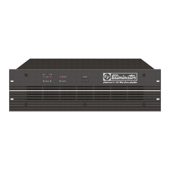
Summary of Contents for Electro-Voice Eliminator
- Page 1 SERVICE MANUAL...
- Page 2 Table of Contents - Safety and Service Instructions - Warranty - Technical specifications - Measuring data - Bill of materials - Spare parts plan - Circuit diagrams Electro-Voice 600 Cecil Street, Buchanan, Michigan 49107 Phone 616/695-6831 Fax 616/695-1304 e-mail fspain@qtm.net...
-
Page 3: Important Safety Instructions
IMPORTANT SAFETY INSTRUCTIONS The lightning flash with arrowhead symbol, within an equi- lateral triangle is intended to alert the user to the presence of uninsulated “dangerous voltage” within the product’s enclosure that may be of sufficient magnitude to constitute a risk of electric shock to persons. The exclamation point within an equilateral triangle is intended to alert the user to the presence of important operating and maintance (servicing) instructions in the... - Page 4 (d): malfunction resulting from misuse or abuse of the product; or (e): malfunction occurring at any time after repairs have been made to the product by anyone other than Electro-Voice or any of its authorized service representatives.
- Page 5 Technical Specifications: S1200, S900, Q44, Q66, Force, Eliminator, Altec Lansing 8140 & 8160 Amplifier at rated conditions, both channels driven with 8Ω loads, unless otherwise specified. S900 / Q44 / S1200 / Q66 / Altec Lansing 8140 / Altec Lansing 8160 /...
-
Page 6: Idling Current Adjustment
MEASUREMENT SPECIFICATIONS: Force & Eliminator power amplifiers printed board assembly names and their corresponding EDP-No.: Force : 84177 Eliminator : 84178 printed board assembly index Main PCB Supply PCB Input PCB LED PCB measuring condition; if not otherwise specified: ∆X = ±1.5 dB... - Page 7 performed at normal room temperature. In case the power amplifier had been operated before, it has to be given several hours for cooling off. 4.2 VCA - OFFSET Periodically (rhythmical) opening and short-circuiting the CNS2.1 and CNS2.2 on the main PCB printed board assembly for channel A;...
-
Page 8: Led Indicator Test
0.9dBu SPEAKER A/B 42.4V 1kHz ∞ Force CH. A 0.9dBu BRIDGED OUT 84.8V 1kHz ∞ Eliminator CH. A/B 0.5dBu SPEAKER A/B 1kHz ∞ Eliminator CH. A 0.5dBu BRIDGED OUT 1kHz 6.2 MAXIMUM INPUT LEVEL: U (E) = +21 dBu 7. GROUND LIFT switch the circuit ground (at the input or the output connector) is measured versus the common ground of the enclosure (contact at the ground terminal, located on the rear panel - or common ground of the mains cord). - Page 9 U(G) U(A) GAIN INPUT(A) S/N-R. Force SPEAKER INPUT A&B OUT A&B -66.2 -55.2 -68.2 -102.2 R(Q) = 50Ω Eliminator SPEAKER INPUT A&B OUT A&B -102 R(Q) = 50Ω Force SPEAKER INPUT A&B OUT A&B -68.2 -57.2 -70.2 R(Q) = 50Ω...
-
Page 12: Bill Of Materials
348415 fan dc 24V 337053 plastic bag 306482 carton 355741 filler, carton 355742 filler, carton 358067 front panel Eliminator 358066 rear panel Eliminator 351353 cover chassis Electronical parts 354645 mains transformer 120/240V 348805 safety component PTC 348341 connector female 3-pin... - Page 13 Ref. No. Part no. Description C0005 329021 cap ceramic 100nF C0006 329021 cap ceramic 100nF C0007 343530 cap electrolytic 47uF/50V C0008 329021 cap ceramic 100nF C0011 354564 cap electr. 6800uF/100V C0012 354564 cap electr. 6800uF/100V C0013 354564 cap electr. 6800uF/100V C0014 354564 cap electr.
- Page 14 Ref. No. Part no. Description C0302 301478 cap electrolytic 22uF/63V C0303 335787 cap ceramic 15pF C0304 335787 cap ceramic 15pF C0305 301458 cap electrolytic 2.2uF/63V C0306 327390 cap mylar 470pF C0307 340988 cap mylar 470nF C0308 301530 cap ceramic 100pF C0309 343532 cap electrolytic 100uF/25V...
- Page 15 Ref. No. Part no. Description D0009 304360 diode 1N 4002 D0010 301254 diode 1N 4148 D0011 301254 diode 1N 4148 D0014 301254 diode 1N 4148 D0015 301254 diode 1N 4148 D0016 304360 diode 1N 4002 D0017 304360 diode 1N 4002 D0018 304360 diode 1N 4002...
- Page 16 Ref. No. Part no. Description D0510 354547 led green D0511 354547 led green D0512 301254 diode 1N 4148 E0001 354859 relay 24V E0100 354859 relay 24V E0300 354859 relay 24V F0001 302582 fuse 1A slow blow F0002 302582 fuse 1A slow blow F0003 348853 fuse 20A slow blow...
- Page 17 Ref. No. Part no. Description Q0105 348421 transistor 2N 3906 Q0106 348422 transistor MPSA 42 Q0107 348423 transistor MPSA 92 Q0108 335763 transistor 2N 3904 Q0109 348421 transistor 2N 3906 Q0110 348422 transistor MPSA 42 Q0111 348423 transistor MPSA 92 Q0112 335763 transistor 2N 3904...
- Page 18 Ref. No. Part no. Description Q0313 348421 transistor 2N 3906 Q0314 335763 transistor 2N 3904 Q0315 348421 transistor 2N 3906 00010 338869 transistor MJE 350 00010 338868 transistor MJE 340 Q0318 348409 transistor 2SC 4793 Q0319 348421 transistor 2N 3906 Q0320 335763 transistor 2N 3904...
- Page 19 Ref. No. Part no. Description R0388 348456 resistor 2x0.22 ohm 5 watt R0391 348456 resistor 2x0.22 ohm 5 watt R0394 348456 resistor 2x0.22 ohm 5 watt R0397 348456 resistor 2x0.22 ohm 5 watt R0408 348593 safety component NTC R0409 348593 safety component NTC R0423 341713...


Need help?
Do you have a question about the Eliminator and is the answer not in the manual?
Questions and answers