
Subscribe to Our Youtube Channel
Related Manuals for Stulz DRH-04


Summary of Contents for Stulz DRH-04
- Page 1 DRH Series GEN1 Ultrasonic Humidifi er Installation, Operation & Maintenance Manual READ AND SAVE THESE INSTRUCTIONS LIRE ET CONSERVER CES INSTRUCTIONS MODELS DRH-04 DRH-08 DRH-06 DRH-16 (April, 2013)
- Page 2 No part of this document may be photocopied, reproduced, or translated into another language for use by anyone other than the owner of the equipment for which this manual is written without the prior written consent of Stulz Air Technology Systems, Inc. (STULZ).
-
Page 3: Table Of Contents
DRH Series GEN1 Ultrasonic Humidifi er Installation, Operation & Maintenance Manual TABLE OF CONTENTS Introduction ........1-1 4.2.1 Air Filter ............4-3 4.2.2 Water Supply Filter/Strainer .......4-3 General ............1-1 4.2.3 Electrical Parts ...........4-3 Safety ............1-1 4.2.4 Float Switches ..........4-4 1.2.1 General ............1-1 4.2.5 Water Tank ..........4-5 1.2.2... -
Page 4: Introduction
STULZ DRH Series Ultrasonic Humidifi ers are de- signed as stand alone direct room humidifi ers. Any CAUTION use beyond this is deemed to be not intended. STULZ is not liable for any damage resulting from improper This unit must be installed according to local use. - Page 5 DRH Series GEN1 Ultrasonic Humidifi er Installation, Operation & Maintenance Manual NOTE CAUTION STULZ offers no warranty protection on humidifi cation systems using controls that are Never attempt to remove the mist guide cover not provided by STULZ. and/or the mist blow tubes while the humidifi - er is operating, or electrical shorts may result.
-
Page 6: Product Warranty
Inc.’s obligation under this warranty is to repair or replace, at its option, free of charge to the customer, any part or parts which are determined by Stulz Air Technology Systems Inc. to be defective for a period of 24 months from date of shipment when a completed start-up form has been submitted to Stulz Air Technology Systems, Inc. -
Page 7: Specifi Cations
DRH Series GEN1 Ultrasonic Humidifi er Installation, Operation & Maintenance Manual 1.4 Specifi cations Type DRH Series Ultrasonic Humidifi er Model DRH-04 DRH-06 DRH-08 DRH-16 Nebulizing capacity (lb/h) 17.6 Qty. of Ultrasonic nebulizers/unit Power source 48VDC Rated power consumption (W) Weight (lb) 19.8... -
Page 8: General Design
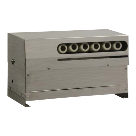
DRH Series GEN1 Ultrasonic Humidifi er Installation, Operation & Maintenance Manual 1.5 General Design The DRH Ultrasonic Humidifi er directly atomizes water, producing a fi ne mist. The humidifi er incorporates high frequency nebulizers to produce ultrasonic waves, a fan to propel the mist out, and an automatic water supply mechanism to maintain the supply water at a constant level. -
Page 9: Solid State Relay
DRH Series GEN1 Ultrasonic Humidifi er Installation, Operation & Maintenance Manual 1.6.12 Solid State Relay Safety control is built into the microprocessor. The voltage applied to the transducer affects the amount The 48 VDC operating voltage for the Ultrasonic of mist produced. Too high a voltage can cause Nebulizer Units is switched on and off by a solid state damage to the transducer and too low a voltage DC relay controlled by the Level Controller. -
Page 10: Installation
STULZ ships all equipment FOB factory. STULZ is not liable for any equipment damage while in transit. STULZ can assist in the claim fi ling process with the freight carrier. Should any such damage be present, notify the STULZ Product Support Group prior to attempting any repairs. Refer to Section 5.0 of this manual for instructions. -
Page 11: Mounting/Placement
Mounting/Placement STULZ ultrasonic humidifi ers are designed for mounting to a fl at surface. Ensure the base is capable of support- ing the weight of the unit. Weight estimates can be found on the installation drawing provided with your unit. -
Page 12: Figure 3- Water Inlet Filter Strainer
DRH Series GEN1 Ultrasonic Humidifi er Installation, Operation & Maintenance Manual CAUTION It is essential that DI or RO water be used as the supply water source to maintain warranty coverage. The use of untreated water will VOID THE WARRANTY. NOTE The water supply piping must be non-corrosive stainless steel or poly tubing rated for use with de-ionized water. -
Page 13: Main Power/Control Wiring
(Amps) 25 ft. 50 ft 75 ft. Prop. On/Off DRH-04 DRH-06 DRH-08 DRH-16 11.8 NOTE: The table above refl ects the correct electrical wire sizing from the control panel to the humidifi ers for three different lengths. Wire sizes listed are for stranded wire only (either THHN or NTW). Do not use solid conductor wire. -
Page 14: Operation
2. Open the water supply valve allowing water to fl ow to the humidifi er. 3. Perform a manual drain cycle to fl ush any particulates from the tank utilizing the system controller (see STULZ Ultra-Series controller IOM manual #OUU0078, Section 5.5.1.2). 4. Set the humidity setpoint to the desired humidity level. -
Page 15: Precautions
DRH Series GEN1 Ultrasonic Humidifi er Installation, Operation & Maintenance Manual 3.4 Precautions Do not remove the air fi lter at the bottom of the humidifi er during operation. Do not block the outlet of the mist blow tubes. It could cause a failure if the mist fl ow is reversed. Drain the water from the water tank for sanitary reasons if the unit is turned off for more than 3 days. -
Page 16: Maintenance/Repairs
When performing maintenance or repairs, care must be taken to ensure small parts such as screws will not be lost. Testing insulation resistance and dielectric withstand voltage should be avoided because the humidifi er incorporates sensitive electronic parts. When parts are replaced, genuine STULZ parts must be used. Contact STULZ Product Support for assistance. (April, 2013) -
Page 17: Maintenance Items And Necessary Tools
DRH Series GEN1 Ultrasonic Humidifi er Installation, Operation & Maintenance Manual Maintenance Items and Necessary Tools Item Cycle Description Necessary Tools Routine Maintenance Air fi lter cleaning. About once a week depending Phillips screwdriver Sect. 4.2.1 on the extent of contamination. The interval should be short- ened if environmental condi- tions are particularly dusty. -
Page 18: Air Filter
DRH Series GEN1 Ultrasonic Humidifi er Installation, Operation & Maintenance Manual 4.2.1 Air Filter 1) Stop the humidifi er. 2) Loosen and remove the fi lter case mounting screws (2 Pcs.) at the lower front of the humidifi er. Photo 1 3) Pull out the fi... -
Page 19: Float Switches
DRH Series GEN1 Ultrasonic Humidifi er Installation, Operation & Maintenance Manual 6) Remove the terminal connectors (3 Ea.) from the sides of the level control board. Photo 6 7) Slide the board out and ensure there is no discoloration, deformation or deterioration of the printed circuit. Photo 7 If any defects are found with the electrical parts, take necessary steps referring to Sect. -
Page 20: Water Tank
DRH Series GEN1 Ultrasonic Humidifi er Installation, Operation & Maintenance Manual 4.2.5 Water Tank 1) Loosen the fan casing mounting screws (4 Pcs.) on the sides of the humidifi er and slide it up from the base. Photo 11 2) Turn the fan casing on it’s side. Remove the screw inside the casing (1 Pcs.) holding the air fl... -
Page 21: Troubleshooting And Repair
DRH Series GEN1 Ultrasonic Humidifi er Installation, Operation & Maintenance Manual 4.3 Troubleshooting and Repair Should any failure occur, make the necessary repairs referring to the following tables. As a rule, power must be turned off when troubleshooting is performed but if it is absolutely necessary to troubleshoot when power is supplied, special attention must be paid to avoid electric shock and short-circuiting. - Page 22 If the humidifi er is operated for a long time with a deteriorated transducer, the nebulizer print plate may fail. The transducers should be replaced using the estimated lifetime of 10,000 to 15,000 hours as the point of reference. STULZ If the cause cannot be located through the above checking, please contact Product Support.
-
Page 23: Preparation For Repairs
DRH Series GEN1 Ultrasonic Humidifi er Installation, Operation & Maintenance Manual Common Repairs/Parts Replacement When parts are replaced, refer to sections “4.4.1 Preparation for Repairs” and “4.4.2 Re-assembling”. 4.4.1 Preparation for Repairs (Removal of Water Tank) 1) Stop the humidifi er, set the power supply circuit breaker (main switch) to “Off”... -
Page 24: Replacing The Temperature Sensor
DRH Series GEN1 Ultrasonic Humidifi er Installation, Operation & Maintenance Manual 4.4.3 Replacing the Temperature Sensor The temperature sensor is mounted to either the fi rst nebulizer print plate or on the front of the water tank depending on when your unit was shipped. Referring to Section 4.4.1, “Preparation for Repairs” steps 1 - 5, place the water tank on a well lit work surface. -
Page 25: Replacing A Transducer
DRH Series GEN1 Ultrasonic Humidifi er Installation, Operation & Maintenance Manual 4.4.4 Replacing a Transducer 1) Referring to Section 4.4.1, “Preparation for Repairs”, place the water tank on a well lit work surface. 2) To replace a transducer, remove the two transducer lead wires, (yellow and orange) from the nebulizer print plate. -
Page 26: Replacing A Nebulizer Print Plate
DRH Series GEN1 Ultrasonic Humidifi er Installation, Operation & Maintenance Manual 4.4.5 Replacing a Nebulizer Print Plate 1) Referring to Section 4.4.1, “Preparation for Repairs”, place the water tank on a well lit work surface. 2) Using a 5.5 mm nut driver, remove the print plate mounting nuts (2 Pcs.) and remove the plate. - Page 27 DRH Series GEN1 Ultrasonic Humidifi er Installation, Operation & Maintenance Manual Note Ensure the elbow is facing the correct direction. 7) Install the new solenoid valve to the fl oat panel and re-install the pipe fi tting. Note Ensure the o-ring is not damaged. If it is damaged, replace it with a new one.
-
Page 28: Product Support Group
STULZ within 30 days of the any other method than UPS ground the customer is purchase date. Spare part sales over 30 days old will responsible for the shipping charges. -
Page 29: Drawings
DRH Series GEN1 Ultrasonic Humidifi er Installation, Operation & Maintenance Manual DRAWINGS 6.1 Layout Drawing of Humidifi er (Covers Removed to Show Parts) The bubble numbers in the drawing coincide with the item numbers listed below: Drain Stub- 1/8” NPT Water Supply Filter/Strainer Level Control Board Mist Guide Tube... -
Page 30: Electrical Circuit Diagrams
DRH Series GEN1 Ultrasonic Humidifi er Installation, Operation & Maintenance Manual 6.2 Electrical Circuit Diagrams Typical Wiring Diagram for Modbus Version From Control Box 48VDC_(-) 48VDC_(+) MODBUS_- MOBBUS_+ MODBUS_GND Termination Resistor Required On Last Unit In The String PCB Level Controller Over Temp Sensor DC(-) - Page 31 DRH Series GEN1 Ultrasonic Humidifi er Installation, Operation & Maintenance Manual Typical Wiring Diagram for Stand-alone Version 48VDC_(-) 48VDC_(+) PCB Level Controller Over Temp Sensor DC(-) DC(+) Solid State Relay Fill Valve Drain Valve High Level Low Level Solenoid Solenoid Switch Switch Pin Number...
- Page 32 DRH Series GEN1 Ultrasonic Humidifi er Installation, Operation & Maintenance Manual (April, 2013) OUD0077D; April, 2013 DRH Series GEN1 Installation, Operation & Maintenance - Specifi ctions are subject to change without notice.
Need help?
Do you have a question about the DRH-04 and is the answer not in the manual?
Questions and answers