
Related Manuals for Stulz DRH


Summary of Contents for Stulz DRH
- Page 1 DRH Series GEN2 Direct Room Humidifier Energy Efficient Ultrasonic Humidifier Installation, Operation and Maintenance Manual Models: DRH 04, 06, 08, 16 Ultrasonic Humidification Installation, Operation and Maintenance Manual...
- Page 2 No part of this document may be photocopied, reproduced, or translated into another language for use by anyone other than the owner of the equipment for which this manual is written without the prior written consent of STULZ Air Technology Systems, Inc. (STULZ).
-
Page 3: Table Of Contents
DRH Series GEN2 Ultrasonic Humidifier IOM Manual Table of Contents Introduction ..................................6 Safety ......................................6 Safety Summary ..............................6 Specifications ....................................8 General Design ....................................9 Main Parts ......................................9 Ultrasonic Nebulizer Unit ............................ 9 Mist Guide ................................. 9 High Water Float Switch ............................ - Page 4 Typical Wiring Diagram for Modbus Version ..................... 36 Typical Wiring Diagram for Stand-Alone Version ..................37 Figures Figure 1. Ultrasonic Humidifier- Model DRH-06 ......................8 Figure 2. Installation of Humidifier ..........................13 Figure 3. Locating the Humidifier ............................ 14 Figure 4. Piping Connections ............................15 Figure 5.
- Page 5 DRH Series GEN2 Ultrasonic Humidifier IOM Manual Nomenclature DRH-04-S Ducted Air Ducted Air Stand Number of Humidifier Humidifier Alone Transducers...
-
Page 6: Introduction
Each unit is designed as a stand-alone direct room humidifier. Any use beyond this is deemed to be not intended. STULZ is not liable for any damage resulting from improper use. The system is designed to be installed indoors unless otherwise noted on the equipment nameplate. - Page 7 Wiring terminations may become loose during transit of the equipment therefore, so verify all wiring terminations are secure prior to operation. Do not attempt to make repairs without the proper tools. STULZ offers no warranty protection on humidification systems using controls that are not provided by STULZ.
-
Page 8: Specifications
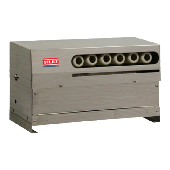
DRH Series GEN2 Ultrasonic Humidifier IOM Manual Figure 1. Ultrasonic Humidifier- Model DRH-06 Specifications Type DRH Series Ultrasonic Humidifier Model DRH-04 DRH-06 DRH-08 DRH-16 Nebulizing capacity (lb/h) 17.6 Qty. of Ultrasonic nebulizers/unit Power source 48VDC Rated power consumption (W) Weight (lb) 19.8... -
Page 9: General Design
51VDC, damage to the transducers and print plates will result. General Design The DRH Ultrasonic Humidifier directly atomizes water, producing a fine mist. The humidifier incorporates high frequency nebulizers to produce ultrasonic waves, a fan to propel the mist out, and an automatic water supply mechanism to maintain the supply water at a constant level. -
Page 10: Water Fill Valve Solenoid
DRH Series GEN2 Ultrasonic Humidifier IOM Manual becoming dirty which would affect the mist output. Water Fill Valve Solenoid The Water Fill Valve Solenoid is a 24VDC solenoid that allows water from the water supply to enter into the tank when energized by the Level Controller. There is an orifice to restrict the flow of water. - Page 11 DRH Series GEN2 Ultrasonic Humidifier IOM Manual must be present at all times to allow the Level Controller microprocessor to monitor the inputs and control the outputs. The microprocessor monitors the on/off command from either the Modbus or the input dry contact (depending on which model was purchased).
-
Page 12: Installation
Any freight claims MUST be done through the freight carrier. STULZ ships all equipment FOB factory. STULZ is not liable for any equipment damage while in transit. STULZ can assist in the claim filing process with the freight carrier. Should any such damage be present, notify... -
Page 13: Site Preparation
DRH Series GEN2 Ultrasonic Humidifier IOM Manual discrepancies to the appropriate authority. Contents of the package: Humidifier Six foot long power cable with moisture-proof, twist-lock connector on one end Installation, Operation and Maintenance manual Avoid dropping or jarring the unit to prevent damage to the internal parts. Always store the unit in a dry location prior to installation. -
Page 14: Mounting/Placement
DRH Series GEN2 Ultrasonic Humidifier IOM Manual The unit must be installed horizontally and level to prevent the float switches from giving a false reading. Prepare hanging bolts for installing from the ceiling or brackets for wall mounting (see Figure 1). The distance from the humidifier to the ceiling should be a minimum of 18”... -
Page 15: Figure 4. Piping Connections
DRH Series GEN2 Ultrasonic Humidifier IOM Manual water conductivity exceeds or is outside the range of standard, routine maintenance intervals to ensure continuous operation will be more frequent than usual. Also, the operating life of the transducers and print plates will be significantly reduced. -
Page 16: Main Power And Control Wiring
DRH Series GEN2 Ultrasonic Humidifier IOM Manual Figure 5. Water Inlet Connector A drain line rated for use with DI water must be provided from the I/8” MPT water tank drain stub in the side of the unit. Connect the drain line to the stub so that overflowing water can be directed into a drain pan or an appropriate place such as an open building drain with an air gap per local and national plumbing codes. -
Page 17: Wire Sizing Control Box To Humidifiers
Figure 6. Electrical Connections Connecting Humidifier(s) to Control Box As a standard, STULZ GEN2 Ultrasonic humidifiers are equipped with a twist lock power connector and (2) RJ45 ports for data communication. The Ultrasonic Control box will also be equipped with an RJ45 port for data communication. The DRH Series Ultrasonic Humidifiers are designed for stand-alone direct room applications. -
Page 18: Multiple Humidifiers (Grouped)
DRH Series GEN2 Ultrasonic Humidifier IOM Manual to make the connection between the field-installed 48VDC power wiring and the factory provided humidifier power cable. RJ45/CAT5 cable (not included) should be used in required length(s) to make the data communications connection between the humidifier and the control box. The factory provided end-of-line termination resistor should be installed in the second RJ45 port. -
Page 19: Operation
Open the water supply valve allowing water to flow to the humidifier. Perform a manual drain cycle to flush any particulates from the tank utilizing the system controller (see STULZ Ultra-Series controller IOM manual #OUU0078, Section 5.5.1.2). Set the humidity setpoint to the desired humidity level. -
Page 20: Precautions
DRH Series GEN2 Ultrasonic Humidifier IOM Manual During operation, the humidifier starts and stops by means of a signal from the control box. The water level in the water tank is maintained by the level controller. If the water level in the tank falls below the safety level for any reason during operation, power to the ultrasonic nebulizers is cut off by the level controller. -
Page 21: Maintenance/Repairs
DRH Series GEN2 Ultrasonic Humidifier IOM Manual Maintenance/Repairs Periodic General Maintenance Systematic, preventive maintenance of the humidifier is recommended for optimum system performance. Routine periodic maintenance should include, but is not limited to the following: • Tightening electrical connections • Cleaning, inspecting the unit’s components visually •... - Page 22 DRH Series GEN2 Ultrasonic Humidifier IOM Manual When parts are replaced, genuine STULZ parts must be used. Contact STULZ Product Support for assistance. Spare replacement parts requests to STULZ Product Support may be made in three ways: Fax: (301) 620-2606 Phone: (888) 529-1266 E-mail: parts@stulz-ats.comMaintenance Items and Tools...
-
Page 23: Air Filter
DRH Series GEN2 Ultrasonic Humidifier IOM Manual Air Filter Stop the humidifier. Loosen and remove the filter case mounting screws (2 Pieces) at the lower front of the humidifier. (Photo 1) Pull out the filter case. (Photo 2) Wash the filter media with clean water. -
Page 24: Float Switches
DRH Series GEN2 Ultrasonic Humidifier IOM Manual • No water leakage from the solenoid valve joint. • No damage to electrical wires or cables. No abnormality of parts then Remove the terminal connectors (3 each) from the sides of the level control board. -
Page 25: Water Tank
DRH Series GEN2 Ultrasonic Humidifier IOM Manual Water Tank Loosen the fan casing mounting screws (4 pieces) on the sides of the humidifier and slide it up from the base. (Photo 11) Turn the fan casing on its side. Remove the screw inside the casing (1 piece) holding the air flow guide (water tank cover).(Photo 12) -
Page 26: Troubleshooting And Repair
DRH Series GEN2 Ultrasonic Humidifier IOM Manual Troubleshooting and Repair See the troubleshooting table below for the remedy to any issues. WARNING Turn off power when undertaking any repairs. Check the humidifier and the surrounding area. Issue Cause Checking Remedy Control box switch turned Visually check switch position. - Page 27 10,000 to 15,000 hours as the point of reference. at (888) 529-1266 or email If the cause cannot be identified, contact STULZ Product Support STULZTechnicalSupport@stulz-ats.com.. If the humidification system is supplied with a water conductivity sensor (optional), ensure the sensor is operating...
-
Page 28: Common Repairs/Parts Replacement
DRH Series GEN2 Ultrasonic Humidifier IOM Manual Common Repairs/Parts Replacement When parts are replaced, refer to Preparation for Repairs and Re- assembling. Preparation for Repairs (Removal of Water Tank) Stop the humidifier, set the power supply circuit breaker (main switch) to Off and close the water supply valve. -
Page 29: Replacing The Temperature Sensor
DRH Series GEN2 Ultrasonic Humidifier IOM Manual Replacing the Temperature Sensor The temperature sensor is mounted to the front of the water tank. Referring to Section 4.4.1, Preparation for Repairs steps 1 to 5, place the water tank on a well-lit work surface. -
Page 30: Replacing A Transducer
DRH Series GEN2 Ultrasonic Humidifier IOM Manual Replacing a Transducer Referring to Section 4.4.1, Preparation for Repairs, place the water tank on a well-lit work surface. To replace a transducer, remove the two transducer lead wires, (yellow and orange) from the nebulizer print plate. (Photo 4) NOTE: Grasp the terminals when removing wires. -
Page 31: Replacing A Nebulizer Print Plate
DRH Series GEN2 Ultrasonic Humidifier IOM Manual Replacing a Nebulizer Print Plate Referring to Section 4.4.1, Preparation for Repairs, place the water tank on a well-lit work surface. Using a 5.5 mm nut driver, remove the print plate mounting nuts (2 Pieces) and remove the plate. -
Page 32: Float Switch
DRH Series GEN2 Ultrasonic Humidifier IOM Manual Float Switch Remove the lock nut on the float switch. Replace the switch with a new one (Photo 10). Level Control Board To replace the level control board, remove the lead wire terminal connectors (3 pieces) from the board (see Photos 6 and 7). -
Page 33: Product Support
Warranty inquiries are to be made through the Technical Support Department at (888) 529- 1266 Monday through Friday from 8:00 a.m. to 5:00 p.m. EST. A service technician at STULZ will troubleshoot the system over the telephone with a field service technician to determine the defect of the part. -
Page 34: Obtaining Spare/Replacement Parts
The customer is responsible for the shipping cost incurred for returning the defective part(s) back to STULZ. Return of defective part(s) must be within 30 days at which time an evaluation of the part(s) is conducted and if the part is found to have an issue a credit will be issued. -
Page 35: Drawings
DRH Series GEN2 Ultrasonic Humidifier IOM Manual Drawings Layout Drawing of Humidifier (Covers Removed to Show Parts) The numbers called out in the drawings above coincide with the unit component item numbers described below: Description Drain Stub- 1/8” MPT With SS Cap... -
Page 36: Electrical Circuit Diagrams
DRH Series GEN2 Ultrasonic Humidifier IOM Manual Electrical Circuit Diagrams Typical Wiring Diagram for Modbus Version... -
Page 37: Typical Wiring Diagram For Stand-Alone Version
DRH Series GEN2 Ultrasonic Humidifier IOM Manual Typical Wiring Diagram for Stand-Alone Version... - Page 38 North American Headquarters STULZ Air Technology Systems, Inc. 1572 Tilco Drive | Frederick, MD 21704 301.620.2033 | Fax: 301.662.5487 | info@stulz-ats.com Technical Support: 888.529.1266 www.stulz-usa.com OUD0134-- Nov. 2019 © STULZ Air Technology Systems, Inc. - Specifications subject to change without notice.
Need help?
Do you have a question about the DRH and is the answer not in the manual?
Questions and answers