Advertisement
Quick Links
12
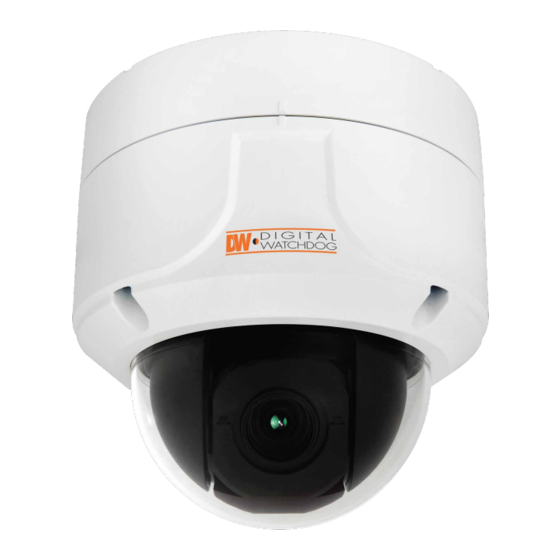
Analog PTZ Outdoor
x
Quick Start Guide
Version 1.01
This equipment has been tested and found to comply with the limits for a Class A digital device, pursuant to part 15 of the FCC Rules.
These limits are designed to provide reasonable protection against harmful interference when the equipment is operated in a
commercial environment. This equipment generates, uses, and can radiate radio frequency energy and, if not installed and used in
accordance with the instruction manual, may cause harmful interference to radio communications. Operation of this equipment in a
residential area is likely to cause harmful interference in which case the user will be required to correct the interferenece at his own
expense.
To disconnect power from the mains, pull out the mains cord plug.
When install the product, ensure that the plug is easily accessible.
PREPARATION
The following items are included with the PTZ camera
DWC-P12CM
Template Sheet
Manual CD
Indoor Ceiling Mount*
Main Body + Surface Mount Bracket
DWC-P12CMS
Quick Manual
Sunshield Ceiling Mount
(Not Included)
Rubber Gasket
9P Terminal Block
DWC-P12WM
DWC-P39POLM
Indoor Wall Mount
Pole Mount
(Not Included)
(Not Included)
Screw & Plastic Anchor-4pcs
DWC-P12WMS
DWC-P39CNM
Sunshield Wall Mount
Corner Mount
Torx Wrench
(Not Included)
(Not Included)
Thank you for purchasing Digital Watchdog's Super Speed Dome PTZ Outdoor Dome Camera.
Before installing the camera, please verify your model and read this guide carefully.
Accessories are optional and sold separately.
TEL: (866) 446-3595
www.Digital-Watchdog.com / technicalsupport@dwcc.tv
Technical Support Hours: Monday-Friday 8:30AM to 8:00PM EST
INSTALLATION
Camera Parts and ID Setup
1
1
1
1
2
2
3
3
2
2
4
4
5
5
Main Body
3
3
6
6
4
4
5
5
7
7
6
6
7
7
Bottom of Main Body
8
8
8
8
9
9
9
9
Surface Mount
Bracket
10
10
INSTALLATION
Terminal Block Connections
Alarm Output
1
- It connects to the alarm lights, siren or lamps,
and it is activated according to the OSD menu
setting.
- There are 1 Alarm Output and it is relay
Alarm Output Slot
Power Input Slot
contact type. Therefore, you do not have to
care about polarity, AC/DC, and isolations
Alarm Input/Sensor Slot
RS-485 Slot
1
between channels. Care must be taken for the
power capacity of relay contact type.
- The sensor types are normal open and
normal close.
2
Alarm Input/Sensor
2
- It connects to IR sensor, IrDA sensor or door
switch. If the sensor is activated, it can activate
to move camera to the specific angle and to
connect the alarm device.
3
- A cable of the sensor should connect to input
1 or 2, and the other should be connected to
'COM' slot.
2
- The sensor types are normal open and
normal close.
1
RS-485 Communication (Keyboard Controller/
3
DVR)
For PTZ control, connect this line to keyboard
and DVR.
5
To control multiple cameras at the same time,
RS-485 communication lines of them are
connected in parallel as shown below.
6
Power
4
- Please check the correct rated power.
- The rated power is marked on the bottom of
the camera.
7
Keyboard
3
4
Controller/DVR
2
0 91 9 2 0 1 2
INSTALLATION
Installation Using Surface Mount Bracket
Template Sheet
1
Drilling the Hole
on the Ceiling
Rubber Gasket
Pass cables through
2
3/4" holes & mount
Bracket.
2
4
5
3
INSTALLATION
Installation Using Ceiling / Wall Mount Bracket*
Ceiling Mount Option
1
Rubber
Gasket
2
8
Rubber
Gasket
3
4
5
6
~
Camera 1 Camera 2 Camera n
7
4
INSTALLATION
(SURFACE MOUNT)
Installation Using Sunshield Dome*
Disassemble the main body with the
surface mount before installation the
camera.
Rubber
Drilling 4 Holes on the Ceiling
1
Gasket
Using provided template sheet, drill a hole
(30mm diameter) on the ceiling panel to
pass cables.
Fixing the Surface Mount Bracket
2
Pass the cables through the ¾" pipe hole,
and screw the surface mount bracket to the
ceiling.
Rubber Gasket
- Before installing the gasket, the hole in the
center is to be cut by knife when only necessary.
Connecting the Cables and the Terminal Block
3
Connect the cables to the terminal block and
then put the terminal block in the slot of the
main body.
3
Fixing the Main Body
4
Screw the main body to the surface mount
bracket by screwing 4 lock-up screws.
Detaching the Protection Film
5
Detach the protection film from the dome
cover after finishing all installation.
Accessories are optional and sold separately.
5
INSTALLATION
(INDOOR)
First Time Bootup and Initial Testing
Wall Mount Option
Check Points before Operation
1
1. Before power is applied, please check the cables carefully.
Rubber Gasket
2. The camera ID of the controller must be identical to that of the camera to be
controlled. The camera ID can be check in the system information of OSD menu.
3. If your controller supports multi-protocols, the protocol must be changed to
match to that of the camera.
4. If you changed camera protocol by changing DIP switch, the change will be
e ective after you reboot the camera.
Disassemble the main body with the
surface mount before installation the camera.
5. Since the operation method can be di erent for each controller available, refer
Drilling 4 Holes on the Ceiling/ Wall and Fixing
1
to the manual for your controller if camera cannot be controlled properly.
the Anchor Bolts
To install the ceiling mount bracket, drill four
holes (6mm diameter/50mm depth) on the
9
ceiling and insert the anchor bolts into the
Preset and Pattern Function Pre-check
hole.
Check how to operate preset, pattern, scan and group
Fixing the Ceiling Mount Bracket
function with keyboard controller/DVR in advance to operate
2
1. Drill a hole (20mm diameter) on the pipe of
camera function using them.
the bracket to pass the cables.
(Refer to system keyboard manual)
2. On the fixed anchor bolts, attach the rubber
gasket and screw the ceiling mount bracket.
Start OSD Menu
Fixing the Surface Mount Bracket
Using the OSD menu, preset, pattern, scan, group and alarm
3
Pass the cables through the hole of the surface
input function can be con gured for each application.
mount bracket, screw the surface mount
Enter 'Preset key + 95' .
bracket to the ceiling mount bracket.
Connecting the Cables to the Terminal Block
Auto Calibration
4
Connect the cables to the terminal block and
If the camera is continuously subjected to very
then put the terminal block in the slot of the
high temperatures (over 50°C or 122°F) for a long
main body.
period, the camera can lose focus and produce
Connecting the Terminal Block
blurry images. In this case, it is recommended to
5
Put the terminal block connected to the cables
turn on AUTO CALIBRATION by running preset 165.
in the slot of the main body.
Fixing the Main Body
If you execute AUTO CALIBRATION, the camera
6
Screw the main body to the surface mount
will calibrate its focus for 10 seconds every 24
bracket by screwing 4 lock-up screws.
hours. To turn OFF this function, please run
preset 166.
Detaching the Protection Film
7
Detach the protection film from the dome
cover after finishing all installation.
Accessories are optional and sold separately.
6
(OUTDOOR)
Wall Mount
1
Ceiling Mount
Option
Rubber Gasket
Option
Disassemble the main body with the surface
2
mount before installation the camera.
Drilling a Hole on the Ceiling and Fixing
1
the Anchor Bolts
To install the ceiling mount bracket, drill four
holes (6mm diameter/50mm depth) on the
ceiling and insert the anchor bolts into the
hole.
Fixing the Ceiling Mount Bracket
2
1. Drill a hole (20mm diameter) on the pipe of
the bracket to pass the cables.
2. On the fixed anchor bolts, attach the
rubber gasket and screw the ceiling
mount bracket.
Fixing the Sunshield Dome
3
Pass the cables through the hole of the
3
Sunshield Dome. Screw the Sunshield Dome to
the ceiling mount bracket.
Connecting the Cables to the Terminal Block
4
Connect the cables to the terminal block and
then put the terminal block in the slot of the
4
main body.
5
Connecting the Terminal Block
5
6
Put the terminal block connected to the
cables in the slot of the main body.
Fixing the Main Body
6
Screw the main body to the surface mount
7
bracket by screwing 4 lock-up screws.
Detaching the Protection Film
7
Detach the protection film from the dome
cover after finishing all installation.
7
8
Advertisement

Subscribe to Our Youtube Channel
Related Manuals for DW x12


Summary of Contents for DW x12
- Page 1 INSTALLATION INSTALLATION INSTALLATION (SURFACE MOUNT) (OUTDOOR) Installation Using Sunshield Dome* Camera Parts and ID Setup Installation Using Surface Mount Bracket Wall Mount Ceiling Mount Option Rubber Gasket Disassemble the main body with the Option Template Sheet surface mount before installation the camera.
-
Page 2: Group Setup
GROUP SETUP OSD MENU RESERVED PRESETS SCAN SETUP (FOR DW’S VMAX, VMAX480 & VMAX Flex) Preset 95 Some preset numbers are reserved to special functions. By using the scan function, you can make the camera to move between 2 he group function allows you to run sequence of presets, pattern,...
Need help?
Do you have a question about the x12 and is the answer not in the manual?
Questions and answers