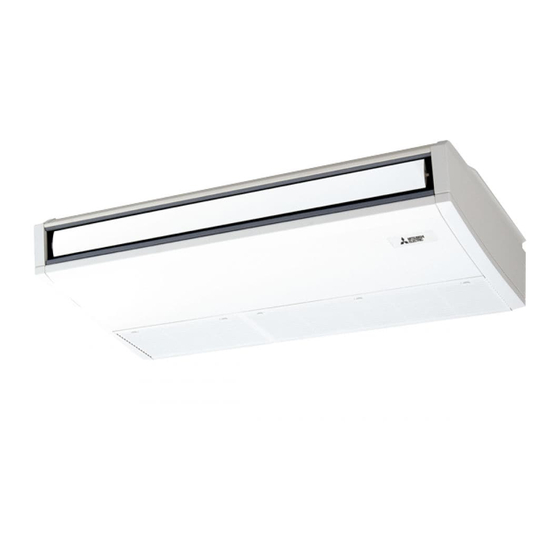
Mitsubishi Electric City Multi Series PCFY-P15NKMU-E Technical & Service Manual
Split-type, heat pump air conditioners
Hide thumbs
Also See for City Multi Series PCFY-P15NKMU-E:
- Technical & service manual (36 pages) ,
- Manual (37 pages) ,
- Operation manual (56 pages)
Table of Contents
Advertisement
SPLIT-TYPE, HEAT PUMP AIR CONDITIONERS
TECHNICAL & SERVICE MANUAL
[Model names]
[Service Ref.]
PCFY-P15NKMU-E
PCFY-P24NKMU-E
PCFY-P30NKMU-E
PCFY-P36NKMU-E
INDOOR UNIT
CONTENTS
1. TECHNICAL CHANGES ......................... 2
2. PART NAMES AND FUNCTIONS .......... 2
3. SPECIFICATION ..................................... 4
4. OUTLINES AND DIMENSIONS .............. 8
5. WIRING DIAGRAM ............................... 11
6. REFRIGERANT SYSTEM DIAGRAM ........ 13
7. MICROPROCESSOR CONTROL ............... 14
8. TROUBLESHOOTING .......................... 21
9. DISASSEMBLY PROCEDURE ............. 30
PARTS CATALOG (OCB500)
Model name
indication
April 2012
No. OCH500
REVISED EDITION-A
R410A
R22
Revision:
• PCFY-P15/24/30/36NKMU-
ER1 have been added in
REVISED EDITION-A.
• Some descriptions have
been modified.
• Please void OCH500.
Note:
• This manual describes only
service data of the indoor
units.
• RoHS compliant products
have <G> mark on the spec
name plate.
Advertisement
Table of Contents

Related Manuals for Mitsubishi Electric City Multi Series PCFY-P15NKMU-E


Summary of Contents for Mitsubishi Electric City Multi Series PCFY-P15NKMU-E
-
Page 1: Table Of Contents
SPLIT-TYPE, HEAT PUMP AIR CONDITIONERS April 2012 No. OCH500 REVISED EDITION-A TECHNICAL & SERVICE MANUAL R410A Indoor unit [Model names] [Service Ref.] PCFY-P15NKMU-E.TH PCFY-P15NKMU-E Revision: • PCFY-P15/24/30/36NKMU- ER1 have been added in PCFY-P15NKMU-ER1.TH REVISED EDITION-A. • Some descriptions have PCFY-P24NKMU-E.TH been modified. -
Page 2: Indoor Unit
Use the specifi ed refrigerant only Never use any refrigerant other than that specifi ed. Doing so may cause a burst, an explosion, or fi re when the unit is being used, serviced, or disposed of. Correct refrigerant is specifi ed in the manuals and on the spec labels provided with our products. We will not be held responsible for mechanical failure, system malfunction, unit breakdown or accidents caused by failure to follow the instructions. -
Page 3: Wired Remote Controller
Wired remote controller Note: The phrase "Wired remote controller" in this manual refers only to the PAR-21MAA. If you need any information for the other remote controller, please refer to either the installation manual or initial setting manual which are included in remote controller's box. -
Page 4: Specification
SPECIFICATION 3-1. SPECIFICATIONS PCFY-P15NKMU-E.TH PCFY-P24NKMU-E.TH PCFY-P30NKMU-E.TH PCFY-P36NKMU-E.TH Service ref. PCFY-P15NKMU-ER1.TH PCFY-P24NKMU-ER1.TH PCFY-P30NKMU-ER1.TH PCFY-P36NKMU-ER1.TH Power source 1-phase 208/230V 60Hz Cooling capacity *1 kW 10.6 *1 Btu/h ( Nominal ) 15 , 000 24 , 000 30 , 000 36 , 000 Power input 0.03 0.04... -
Page 5: Sound Level
3-2. ELECTRICAL PARTS SPECIFICATIONS PCFY-P30NKMU-E.TH Service Ref. PCFY-P30NKMU-ER1.TH PCFY-P15NKMU-E.TH PCFY-P24NKMU-E.TH Symbol PCFY-P15NKMU-ER1.TH PCFY-P24NKMU-ER1.TH PCFY-P36NKMU-E.TH PCFY-P36NKMU-ER1.TH Parts name Room temperature TH21 Resistance 30°F/15.8kΩ, 50°F/9.6kΩ, 70°F/6.0kΩ, 80°F/4.8kΩ, 90°F/3.9kΩ, 100°F/3.2kΩ thermistor Liquid pipe thermistor TH22 Resistance 30°F/15.8kΩ, 50°F/9.6kΩ, 70°F/6.0kΩ, 80°F/4.8kΩ, 90°F/3.9kΩ, 100°F/3.2kΩ Gas pipe thermistor Resistance 30°F/15.8kΩ, 50°F/9.6kΩ, 70°F/6.0kΩ, 80°F/4.8kΩ, 90°F/3.9kΩ, 100°F/3.2kΩ... - Page 6 3-4. NC CURVES PCFY-P15NKMU-E.TH PCFY-P24NKMU-E.TH PCFY-P15NKMU-ER1.TH PCFY-P24NKMU-ER1.TH External static pressure : 0Pa External static pressure : 0Pa Power source : 208V, 230V, 60Hz Power source : 208V, 230V, 60Hz High Middle2 High Middle2 Middle1 Middle1 70.0 70.0 65.0 65.0 60.0 60.0 NC-60 NC-60...
- Page 7 3-5. FRESH AIR INTAKE AMOUNT & STATIC PRESSURE CHARACTERISTICS ■ PCFY-P15NKMU-E.TH PCFY-P15NKMU-ER1.TH How to read curves 50(20) Duct characteristics Curve in the at site graphs Q … Designed amount of fresh air intake -50(-20) <CMM(CFM)> A … Static pressure loss of fresh air -100(-40) intake duct system with airflow -150(-60)
-
Page 8: Outlines And Dimensions
OUTLINES AND DIMENSIONS PCFY-P15NKMU-E.TH Unit : inch(mm) PCFY-P15NKMU-ER1.TH OCH500A... - Page 9 PCFY-P24NKMU-E.TH Unit : inch(mm) PCFY-P24NKMU-ER1.TH OCH500A...
- Page 10 PCFY-P30NKMU-E.TH Unit : inch(mm) PCFY-P30NKMU-ER1.TH PCFY-P36NKMU-E.TH PCFY-P36NKMU-ER1.TH OCH500A...
-
Page 11: Wiring Diagram
WIRING DIAGRAM PCFY-P15NKMU-E.TH PCFY-P24NKMU-E.TH PCFY-P30NKMU-E.TH PCFY-P36NKMU-E.TH LED on indoor board for service NAME SYMBOL NAME SYMBOL Mark Meaning Function I. B INDOOR CONTROLLER BOARD TH22 THERMISTOR PIPE TEMP. DETECTION / LIQUID Main Power supply (Indoor unit) LED1 Main power supply CN24 (32ºF/15ΚΩ, 77ºF/5.4ΚΩ... - Page 12 PCFY-P15NKMU-ER1.TH PCFY-P24NKMU-ER1.TH PCFY-P30NKMU-ER1.TH PCFY-P36NKMU-ER1.TH LED on indoor board for service NAME SYMBOL NAME SYMBOL Mark Meaning Function I. B INDOOR CONTROLLER BOARD TH22 THERMISTOR PIPE TEMP. DETECTION / LIQUID Main Power supply (Indoor unit) LED1 Main power supply (32ºF/15kΩ, 77ºF/5.4kΩ Detect) CN24 EXTERNAL HEATER CONNECTOR...
-
Page 13: Refrigerant System Diagram
REFRIGERANT SYSTEM DIAGRAM PCFY-P15NKMU-E.TH PCFY-P24NKMU-E.TH PCFY-P30NKMU-E.TH PCFY-P36NKMU-E.TH PCFY-P15NKMU-ER1.TH PCFY-P24NKMU-ER1.TH PCFY-P30NKMU-ER1.TH PCFY-P36NKMU-ER1.TH Refrigerant flow in cooling Refrigerant flow in heating Strainer (#100 mesh) Gas pipe thermistor TH23 Gas pipe Liquid pipe thermistor TH22 Flare connection Liquid pipe Heat exchanger Linear expansion valve Strainer1 (#50 mesh) Strainer2 (#100 mesh) Strainer (#100 mesh) -
Page 14: Microprocessor Control
MICROPROCESSOR CONTROL INDOOR UNIT CONTROL 7-1. COOL OPERATION <How to operate> Press POWER ON/OFF button. TIME SUN MON TUE WED THU FRI SAT TIMER AFTER AFTER Press the operation MODE button to display COOL. ERROR CODE FUNCTION û Fû C FILTER û... - Page 15 Control modes Remarks Control details 3. Drain pump 3-1. Drain pump control •Drain pump is always ON during the COOL and DRY mode operation. (Regardless of the thermo ON/OFF) •When the operation mode has changed from the COOL or DRY to the others (including Stop), the drain pump will be kept on for 3 minutes, then turns OFF.
-
Page 16: Dry Operation
7-2. DRY OPERATION <How to operate> Press POWER ON/OFF button. TIME SUN MON TUE WED THU FRI SAT TIMER AFTER AFTER Press the operation MODE button to display DRY. ERROR CODE FUNCTION û Fû C FILTER û Fû C WEEKLY Press the TEMP. -
Page 17: Fan Operation
7-3. FAN OPERATION <How to operate> Press POWER ON/OFF button. TIME SUN MON TUE WED THU FRI SAT Press the operation MODE button to display FAN. TIMER AFTER AFTER ERROR CODE FUNCTION û Fû C FILTER û Fû C WEEKLY SIMPLE ONLY1Hr. -
Page 18: Heat Operation
7-4. HEAT OPERATION <How to operate> Press POWER ON/OFF button. Press the operation MODE button to display HEAT. TIME SUN MON TUE WED THU FRI SAT Press the TEMP. button to set the desired temperature. TIMER AFTER AFTER ERROR CODE FUNCTION NOTE: The set temperature changes 2°F when the button is... - Page 19 From the preceding page Control modes Control details Remarks 2-3. Thermo OFF mode 2. Fan When the thermostat function changes to OFF, the indoor fan operates in [Extra low]. 2-4. Heat defrosting mode The indoor fan stops. 3-1. Drain pump control 3.
- Page 20 7-5. AUTO OPERATION [AUTOMATIC COOL/HEAT CHANGE OVER OPERATION] <How to operate> Press POWER ON/OFF button. TIME SUN MON TUE WED THU FRI SAT Press the operation MODE button to display AUTO. TIMER AFTER AFTER ERROR CODE FUNCTION Press the TEMP. button to set the desired temperature. û...
-
Page 21: Troubleshooting
TROUBLESHOOTING 8-1. HOW TO CHECK THE PARTS PCFY-P15NKMU-E.TH PCFY-P24NKMU-E.TH PCFY-P30NKMU-E.TH PCFY-P36NKMU-E.TH PCFY-P15NKMU-ER1.TH PCFY-P24NKMU-ER1.TH PCFY-P30NKMU-ER1.TH PCFY-P36NKMU-ER1.TH Parts name Check points Room temperature Disconnect the connector then measure the resistance with a tester. thermistor (TH21) (At the ambient temperature 50 F~86 F) Liquid pipe thermistor (TH22) Normal... - Page 22 8-1-1. Thermistor <Thermistor characteristic graph> < Thermistor for lower temperature > Room temperature thermistor (TH21) Thermistor for Liquid pipe temperature thermistor (TH22) lower temperature Gas pipe temperature thermistor (TH23) Thermistor R =15kΩ ± 3% Fixed number of B=3480 ± 2% Rt=15exp { 3480( 273+(t-32)/1.8 30°F...
- Page 23 <Output pulse signal and the valve operation> Closing a valve : 1 → 2 → 3 → 4 → 1 Output Output Opening a valve : 4 → 3 → 2 → 1 → 4 (Phase) The output pulse shifts in above order. Φ1 Φ2 Note:...
- Page 24 8-1-3. DC Fan motor (fan motor/indoor controller circuit board) Check method of DC fan motor (fan motor/indoor controller circuit board) Notes · High voltage is applied to the connecter (CNMF) for the fan motor. Pay attention to the service. · Do not pull out the connector (CNMF) for the motor with the power supply on. (It causes trouble of the indoor controller circuit board and fan motor.) Self check...
-
Page 25: Function Of Dip Switch
8-2. FUNCTION OF DIP SWITCH Operation by switch Effective Switch Pole Function Remarks timing Thermistor <Room temperature Address board Built-in remote controller Indoor unit detection> position <Initial setting> Filter clogging detection Provided Not provided Filter cleaning 2,500 hr 100 hr 1 2 3 4 5 6 7 8 9 10 Note : Fresh air intake... - Page 26 Effective Switch Pole Operation by switch Remarks timing Address board * Ceiling height can be changed depending on SWA setting. (High ceiling) Under <Initial setting> Ceiling operation (Standard) height (Silent) selector suspension High ceiling Silent Standard P15, P24 8.2ft.(2.5m) 8.9ft.(2.7m) 11.5ft.(3.5m) 13.8ft.(4.2m) P30, P36...
- Page 27 Effective Switch Pole Operation by switch Remarks timing <Initial setting> • To operate each indoor unit by each remote controller when installed 2 indoor units or more are near, Pair No. setting is necessary. Pattern A Pair No. setting is available with the 4 patterns (Setting patters A to D). Make setting for J41, J42 of indoor controller board and the Pair No.
- Page 28 8-3. TEST POINT DIAGRAM 8-3-1. Indoor controller board PCFY-P15NKMU-E.TH PCFY-P24NKMU-E.TH PCFY-P30NKMU-E.TH PCFY-P36NKMU-E.TH PCFY-P15NKMU-ER1.TH PCFY-P24NKMU-ER1.TH PCFY-P30NKMU-ER1.TH PCFY-P36NKMU-ER1.TH CN4Y CN60 i-See sensor Linear expansion valve (LEV) output 12VDC pulse output CN6Y CN52 i-see sensor motor output Remote indicator 12VDC pulse output 1-2: Status lamp 12VDC (1 : +) CN3A Fan motor output (SW1-5 OFF) Connect to the terminal block (TB15)
- Page 29 8-3-2. Address board PCFY-P15NKMU-E.TH PCFY-P24NKMU-E.TH PCFY-P30NKMU-E.TH PCFY-P36NKMU-E.TH PCFY-P15NKMU-ER1.TH PCFY-P24NKMU-ER1.TH PCFY-P30NKMU-ER1.TH PCFY-P36NKMU-ER1.TH Ceiling height Function setting selector SW12 SW11 SW14 Address setting Address setting Option selector Branch No. 10ths DIGIT 1st DIGIT OCH500A...
-
Page 30: Disassembly Procedure
DISASSEMBLY PROCEDURE PCFY-P15NKMU-E.TH PCFY-P24NKUM-E.TH Be careful when removing heavy parts. PCFY-P30NKMU-E.TH PCFY-P36NKMU-E.TH (Photo: PCFY-P36NKMU-E.TH) PCFY-P15NKMU-ER1.TH PCFY-P24NKUM-ER1.TH PCFY-P30NKMU-ER1.TH PCFY-P36NKMU-ER1.TH OPERATING PROCEDURE PHOTOS & ILLUSTRATIONS Figure 1 1. Removing the air intake grille (1) Slide the air intake grille holding knobs (at 2 or 3 loca- tions) to the rear to open the air intake grille. - Page 31 OPERATING PROCEDURE PHOTOS & ILLUSTRATIONS 3. Removing the room temperature thermistor (TH21) Photo 4 Casing (1) Remove the air intake grille. (See Figure 1, 2) (2) Remove the screw from the beam and remove the beam. (See Photo 1) (3) Remove 2 screws from the electrical cover, and remove the electrical cover.
- Page 32 OPERATING PROCEDURE PHOTOS & ILLUSTRATIONS 5. Removing the fan (3 connection) (1) Remove the air intake grille. (See Figure 1, 2) Photo 9 (2) Remove the screw from the beam and remove the beam. (See Photo 1) (3) Remove 2 screws from the electrical cover, and remove the electrical cover.
- Page 33 OPERATING PROCEDURE PHOTOS & ILLUSTRATIONS Photo 12 7. Removing the vane motor (1) Remove the air intake. (See Figure 1, 2) Vane motor and cover Connector (2) Remove the right side panel. (See Figure 3) (3) Remove the connector of vane motor. (4) Remove 2 screws of vane motor cover , then remove vane motor.
- Page 34 OPERATING PROCEDURE PHOTOS & ILLUSTRATIONS Photo 17 10. Removing the pipe thermistors/Liquid (TH22) and Gas (TH23) (1) Remove the air intake grille. (See Figure 1, 2) (2) Remove the left and right side panels. (See Figure 3) (3) Remove the under panel. (See Photo 13) (4) Remove the drain pan.
- Page 35 OPERATING PROCEDURE PHOTOS & ILLUSTRATIONS Photo 21 13. Removing the heat exchanger and LEV (1) Remove the air intake grille. (See Figure 1, 2) (2) Remove the beam. (See Photo 1) (3) Remove the electrical cover. (See Photo 1) (4) Pull the electrical box downward. (See Photo 2) (5) Disconnect the connector CN60 (white) from the indoor controller board.
- Page 36 HEAD OFFICE : TOKYO BLDG., 2-7-3, MARUNOUCHI, CHIYODA-KU TOKYO 100-8310, JAPAN Copyright 2011 MITSUBISHI ELECTRIC CORPORATION Distributed in Apr. 2012 No. OCH500 REVISED EDITION-A Distributed in Aug. 2011 No. OCH500 New publication, effective Apr. 2012 Made in Japan Specifications are subject to change without notice.