Table of Contents
Advertisement
NOTICE: SAVE THESE INSTRUCTIONS
model(s):
PF100 Pellet Pro Furnace
PlEASE rEAd ThIS ENTIrE mANuAl bEFOrE YOu INSTAll ANd uSE YOur NEw FurNACE. FAIlurE TO
FOllOw INSTruCTIONS mAY rESulT IN PrOPErTY dAmAgE, bOdIlY INjurY, Or EvEN dEATh.
FOr uSE IN ThE u.S. ANd CANAdA. SuITAblE FOr INSTAllATION IN mObIlE hOmES (SEE Pg. 17).
IF ThIS PEllET FurNACE IS NOT PrOPErlY INSTAllEd, A hOuSE FIrE mAY rESulT. FOr YOur SAFETY, FOllOw
INSTAllATION dIrECTIONS.
CONTACT lOCAl buIldINg Or FIrE OFFICIAlS AbOuT rESTrICTIONS ANd INSTAllATION INSPECTION
rEQuIrEmENTS IN YOur ArEA.
CONTACT YOur lOCAl AuThOrITY (SuCh AS muNICIPAl buIldINg dEPArTmENT, FIrE dEPArTmENT, FIrE
PrEvENTION burEAu, ETC.) TO dETErmINE ThE NEEd FOr A PErmIT.
CETTE guIdE d'uTIlISATION EST dISPONIblE EN FrANCAIS. ChEz vOTrE CONCESSIONNAIrE dE hArmAN.
Installation & Operating manual
SAFETY NOTICE
SAvE ThESE INSTruCTIONS.
!
hOT SurFACES!
Glass and other surfaces are hot during
operation and cool down.
hot glass will cause burns.
• Do not touch glass until it is cooled
• NEVER allow children to touch glass
• Keep children away
• CAREFULLY SUPERVISE children in same room as
stove.
• Alert children and adults to hazards of high temperatures.
high temperatures may ignite clothing or other
flammable materials.
• Keep clothing, furniture, draperies and other flammable
materials away.
NOTE
To obtain a French translation of this manual, please
contact your dealer or visit www.harmanstoves.com
Pour obtenir une traduction française de ce manuel, s'il
vous plaît contacter votre revendeur ou visitez www.
harmanstoves.com
WARNING
3-90-08101R23_06/13
Advertisement
Table of Contents

Related Manuals for Harman PF100


Summary of Contents for Harman PF100
- Page 1 IN YOur ArEA. CONTACT YOur lOCAl AuThOrITY (SuCh AS muNICIPAl buIldINg dEPArTmENT, FIrE dEPArTmENT, FIrE PrEvENTION burEAu, ETC.) TO dETErmINE ThE NEEd FOr A PErmIT. CETTE guIdE d’uTIlISATION EST dISPONIblE EN FrANCAIS. ChEz vOTrE CONCESSIONNAIrE dE hArmAN. SAvE ThESE INSTruCTIONS. 3-90-08101R23_06/13...
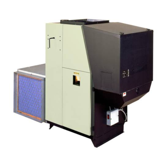
- Page 2 Parts locator Fan Control Hopper Lid Latches Vent Pipe Hopper Combustion Blower cover Heat Exchanger Shaker Handle Combustion Blower 3 Speed Switch Control Cover Outer Door Latches Outer Door Viewing Glass Filter Box 3-90-08101R23_06/13...
-
Page 3: Table Of Contents
= Contains updated information harman Central heating Appliances are built and tested to be complete home heating solutions. As with any Central heat system, a backup heating system may be required in the event of power outages or during appliance service or maintenance. -
Page 4: Assembly
Assembly Filter box (Cold Air return) Top (same as bottom) Solid Side Panel Switch Blower access Panel Filter Frame Panel Blower access Panel Cover Bottom (same as top) Fig. 3 Assembling Filter box Tek screw from outside The cold air return filter box can be assembled with the filter Solid Side Panel frame on either side or the back, provided there is access to the combustion blower and flue area. - Page 5 Assembly Assembling Filter box, Cont’d Filter Frame Panel 3. Place the filter frame panel inside the bottom and inside the solid panel corner. See Fig. 6 for corner detail. Make sure that the filter opening is up.See Fig. 5 Hold the filter Filter opening must be up panel to the solid panel with a Tek screw in the middle hole of the solid panel, and one in the bottom middle hole under the filter opening. NOTE: do not put any screws into any of the top holes at this time. Fig. 5 Fig. 6 4. Place the remaining panel, (in this case the blower access Open Side Panel panel) in the bottom panel and into the corner of the solid panel. See Fig. 7. Make sure that the panel is in the upright position. There are no cover mounting holes in the bottom...
- Page 6 Assembly Assembling Filter box, Cont’d 5. Place the top on the filter box as shown in figure 8. At this time all Tek screws can be inserted around the filter box. Note: Except for the (6) screws that attach the blower access panel in place. There should not be any screws protruding from the box on the side toward the furnace. Also DO NOT put a screw into the top center of the filter panel as a screw in this location will interfere with the filter access cover. 6. Pry out the two knockouts in the top of the box and install the flex connector and the switch. See Fig. 9. Note: Don’t forget the HI-MED-LO switch label on the switch before the locknut.Make sure that the setscrew on the flex connector is not pointing toward the furnace end of the box when the locknut is fully tightened.The filter box is now ready Fig. 8 to install onto the furnace. Follow the Blower mounting instructions on page 7 before continuing to step #7. 3 Speed Switch Note: The blower should be mounted on the furnace before the filter box for ease of distribution blower installation. Note: It is best to wait until the blower, filter box, and cold air return duct work is installed before installing the filter and Flex connector side panel. 7. After the Filter Box is installed on the furnace the electrical wiring to the three speed switch needs to be completed.
- Page 7 Assembly blower Assembly Install the blower mounting brackets on the blower as shown in Fig. 11. 1. Install (4) Tek screws on each side where shown in Fig. 11. Start with the two center screws. NOTE: There are two small holes in the discharge end of the blower that match the two center holes on the small angle of the blower bracket. The two (2) outer holes are drilled by theTek screws. 2. Mount blower with brackets installed on the furnace as shown in Fig. 12. Each side will require 6 Tek screws. NOTE: The furnace blower opening is made large enough for Fig. 11 Mounting Screws the use of any of the 3 offered blowers. The blower mounting brackets will fit either blower. The inner hole pattern is for the 1000 CFM blower and the outer pattern is for the 1450 or 1638 CFM blowers. NOTE: These blower motors are not designed to be operated without any positive static back pressure. OPErATION wIThOuT SuPPlY duCTwOrK Or IN FrEE AIr wIll CAuSE mOTOr OvErlOAd ANd PrEmATurE FAIlurE.
- Page 8 Assembly Firebrick installation-required Firebrick The firebrick is shipped in the ash pan. It will need to be placed on the brick shelf as shown in Fig. 15. It can be installed with either face to the fire. Hold the brick longways and slide it down into the slot on the shelf. There is a stop at the rear of the shelf to stop the rearward travel.The brick just sits on the shelf in the upright position. Fig. 15 Baffle installation The upper heat exchanger baffle comes shipped along side the ashpan. Remove the ashpan and the baffle. This upper baffle needs to be installed before operating the furnace.
-
Page 9: Venting
venting design The first thing needed is deciding where and how the furnace will be installed. Things that need to be taken into consideration are Venting, Supply and Return Ducting, Electrical, and Condensation Drainage (if A/C is installed). Don’t forget access to the furnace for service. When the return air inlet position is known, the filter box and distribution blower can be installed. After the furnace is set into place, the venting can be completed. Fig. 1 venting use 4” pellet vent pipe only. A combustion blower is used to extract the combustion gases from the firebox. This creates a negative pressure in the firebox and a positive pressure in the venting system as shown in fig. 2. The longer the vent pipe and more elbows... - Page 10 venting NOTE: use only 4” diameter “Pl” venting system. Fig. 18 be sure to inspect and clean exhaust venting system frequently. INSTAllATION IS TO bE PErFOrmEd bY A QuAlIFIEd 1” INSTAllEr. dO NOT INSTAll A FluE dAmPEr IN ThE EXhAuST vENTINg SYSTEm OF ThIS uNIT. 4”...
- Page 11 venting Venting Configuration Graph Fig. 19 To reduce probability of reverse drafting during a Hearth & Home Technologies strongly recommends the use power failure, hearth & home Technologies strongly of outside air for all pellet furnace applications. recommends: Per national building codes, consideration must be given • Installing the pellet vent with a minimum vertical rise of to combustion air supply for all appliances in the vicinity five feet. Preferably terminating above the roof line.
- Page 12 venting requirements for Terminating the venting J. The clearance to a non-mechanical air supply inlet to the building or the combustion air inlet to any other appliance WARNING: Venting terminals must not be recessed into a must be a minimum of 48”. wall or siding. K. The clearance to a mechanical air supply inlet must be a NOTE: Only PL vent pipe wall pass-throughs and fire stops minimum of 10 feet. should be used when venting through combustible materials. L. The clearance above a paved sidewalk or a paved NOTE: Always take into consideration the effect the driveway located on public property must be a minimum prevailing wind direction or other wind currents will cause of 7 feet.
- Page 13 venting and Clearances Clearances to combustibles If installing the furnace in a room separated from the remaining living spaces, the minimum size of the room must be no smaller than 8’ x 8’. See Fig. 21. The reason for this is heat build-up and required space for service and normal operation.This is the minimum size of the room even if it is built of non-combustible material. High and low air vents MUST be installed between the room and the remaining living space. Each vent should be at least 72 square inches in area. ( The vent size will need to be increased if there is no return air ducting system.) The striped areas are the minimum clearances to combustibles Floor Protector which is 36” from stove body, not the hopper or blower. The shaded area indicates the required floor protection area. The furnace requires 48” x 52” of floor protection centered around the skidplate footprint. Flooring should be a minimum of 26 gauge sheet metal covering the installation clearance area and 18” in front of, and 8” to either side of the ash pan door. 18” The 18” clearance from the hopper end is a manufacturer’s recommendation for adding pellets and/or servicing the feeder 48” wide mechanism.
- Page 14 venting and Installation The shaded area is where the clearance for the PL vent pipe must be maintained at 3”. After the venting leaves the shaded area it may be installed as per the vent manufacturer instructions. (Only listed 4” pellet vent wall pass-throughs and fire stops may be used.) See Fig. 23 & 25. ” ” See NOTES: on page 12 Fig. 25 Fig. 23 This furnace may be used and installed into an existing Chimneys taller than 20’ above the connection will require a masonry or Class A metal chimney.
-
Page 15: Installation
Installation Outside Air The use of outside air is optional. Connecting to outside air may be required by local codes, and is strongly recommended. To install outside air, use 2¾” I.D. metal flex pipe, part # 2-00-08544 (12’6”length) or part #2-00- 08545 (25’ length). There is a break-away hole on the rear panel which must be removed before connecting the flex pipe. See Fig. 28. The pipe should be run outside and terminate 3 feet or more below or 1 foot or more to the Inlet Cover part# side of the vent pipe outlet. Never terminate the outside 1-10-09542 Fig. 27 air above the vent pipe outlet. The maximum length of this pipe is 25 feet. Inlet cover, part #1-10-09542 should be used to keep birds, rodents etc.out of the inlet pipe. See Fig. 27. NOTE: If outside air is installed, the inlet cover should not be placed in an area where drifting of snow or ice will build Outside Air Pipe Knockout up, blocking the intake air supply. Only metal Intake Flex should be used for the Outside Air Supply connection. Only a screened or rodent protected Outside Air Intake cover should be used as an outside weather cover. The Outside Air Intake Pipe is inside the Feeder Cover and to the right of the feeder motor. The 2 ¾” steel flex pipe is made to slide over the outside of the Air Intake Pipe. See Fig. 29. It should be held into place with some silicone, foil tape, or a hose clamp.(not supplied) Heat rises in the house and leaks out at upper levels. This air must be replaced with cold air from outdoors which flows into lower levels of the house. Vents and chimneys into Fig. - Page 16 Installation wall Control wiring The Wall Control sends and receives information from the control board through a 4 wire Datacom cable. There is a 100’ length of this cable supplied with the furnace. 100’ lengths of this cable can also be ordered separately, part #3-20-02583. Alternately, any Datacom cable -CAT3- 2 twisted pair 24ga solid wire can be acquired at a local electrical supply house. Also any CAT3-24ga. solid wire 2, 3, or 4 pair cable can be used because they all have the same pair color combinations. The maximum length of wall control wiring is 100 feet. The furnace connecting point is a 4 pole screw terminal block on the side of the hopper just around the corner to the right of the control. Follow the wiring instructions on the label alongside the terminal block. See Fig. 31. Fig. 30 CAuTION: With this small gauge of wire, care must be taken not to overtighten the terminal screws thus, breaking the wire. There are tie-wrap holes in the face of the hopper aprox. every 6” to keep the cable secure and out of the way. The Wall Control is made to fit on a standard wall case electrical box. It could also be mounted directly to a stud using 2 drywall screws. In either case the screws should be turned in and tested for a snug fit when the Wall Control is...
-
Page 17: Mobile Home Requirements
1. The furnace must be hooked up to an outside air source. (see page 15) 2. The furnace must be secured or bolted to the floor of the mobile home. Use lag bolts through the provided holes (see below). 3. The furnace must be grounded to the frame of the mobile home. PF100 4. Floor protection and clearance specifications must be followed, including the minimum room size of 8 feet by 8 feet. EXISTINg 5. As in any installation, the furnace must be vented to uNIT the outside, using only approved 4 inch pellet venting materials. - Page 18 Installing duct recommendations for Supply Air and return Air duct Adding Air Conditioning to the pellet furnace. sizing. An easy rule of thumb for A/C CFM blower size is, .75 to The speed or velocity of air moving through duct systems 1 CFM for each square foot of conditioned space. (std. 8’ increases as the duct decreases in size with the same CFM ceiling height) blower. The sound of air flowing through the duct increases This furnace can be fitted with an air conditioning coil as the velocity increases. Therefore the largest duct size mounted in the supply air plenum.
- Page 19 Installation FAN/hIgh lImIT CONTrOl High limit fan control Installation & Set-up 1. The Fan Control must be placed in the discharge plenum approximately 11 inches above the discharge opening of the furnace, as close to center as possible. Note: The best place is on the same side as the ash door because of ease of access. See Fig. 35. Note: Care must be taken when installing the Fan Control when an air conditioning A Coil is used. The Fan Control must always be installed below the A Coil in low plenum installations. 2. Install the flex and wiring. 3. Make sure that the flue venting will not interfere with the flex to the Fan Control. 4. Pry out one of the bottom knockouts of the Fan Control. Fig. 35 Install the 90 degree flex connector as shown in Fig. 36.
- Page 20 Installation Installing Electrical Power: To install power to the furnace first remove the cover on the circuit breaker junction box shown. Inside you will find the main terminal block.(See wiring diagram on page 36 for location of main terminal block and proper power connections). In the bottom of the box a knockout hole is provided for the incoming wire. The minimum recommended circuit is 15 Amp 120 V.A.C. 60 Hz. This furnace should be the only appliance on the circuit. This furnace should never be powered by the use of an extension cord. The recommended high and low voltages are, 130 V.A.C. 60 Hz maximum high voltage, and 113 V.A.C. 60 Hz minimum low voltage. The furnace will continue to operate at voltages as low as 105 V.A.C. , although it can not be guaranteed that automatic ignition will occur. Also, there is the possibility of a distribution...
-
Page 21: Operation
Operation Fan Control Hopper Lid Latches Vent Pipe Hopper Combustion Blower Cover Heat Exchanger Combustion Blower Cleaning Handle 3 Speed Switch Control Cover Outer Door Latches Outer Door Filter Box Fig. 40 Viewing Glass The Control The control can be covered as shown above, or uncovered as shown at left. There is a pair of slots provided for each position. Simply move the cover to the desired position by placing the tabs on the cover in the proper slots. WARNING dO NOT STOrE FuEl Or OThEr COmbuSTIblE mATErIAl wIThIN INSTAllATION ClEArANCE... -
Page 22: Combustion Blower
Operation Power Light Feed adjuster Indicates power to the Sets the maximum feed rate control, and is also used during “Test” to check Test the Low Fuel Sensor Runs all motors ** at full operation. speed for one minute to check operation. - Page 23 Operation wall Control The wall control acts like a thermostat, a thermister in the wall control is sending temperature information back to the micro processor on the furnace. This information is used to Temperature Dial determine the need to increase or decrease the size of the fire according to the temperature demand. Setting The room Temperature To set the room temperature, simply turn the temperature dial to the desired setting. The control and the furnace will then perform to achieve the set temperature. Note: The minimum temperature you can set with a full counter-clockwise knob position is 58 degrees. The maximum temperature you can set with a full clockwise knob Low Fuel Light position is 90 degrees.
- Page 24 Operation Starting A Fire Automatically ImPOrTANT: be sure there is no fuel or other combustibles in the ash pan prior to lighting. 1. Turn mode Selector to “OFF”. This resets the control in addition to turning it off. 2. Fill hopper with pellets. When filling the hopper check for excessive fines in the bottom of the hopper. Fines are small pieces of broken pellets (sawdust). Fines do not flow easily and often build up on the hopper funnel bottom angles. These fines can be pushed into the feeder opening and then fill the hopper with pellets. As Fig. 46 the system works, they will be burned. 3. Clean burnpot with scraper, if necessary. This is usually a weekly maintenance procedure. Cleaning the burn pot with the scraper with a small amount of new fuel in the...
- Page 25 Operation 4. If starting after an empty hopper, turn Feed Adjuster to “TEST” (for one 60 second cycle). This will charge pellets into the auger tube and also allow you to check the motors for operation. NOTE: The auger motor will not operate with the furnace door open. 5. Turn Feed Adjuster to #4. If this is your first fire, or you are trying different pellets, set the feed adjuster to #4, Fig. 50. This is a conservative number and will probably need to be increased if maximum BTU output is desired.
- Page 26 NOTE: do not burn garbage, gasoline, naphtha, engine oil, or other inappropriate materials in the PF100. Store pellets in the manufacturer’s wrapping until needed to prevent pellets from absorbing moisture. do not store fuel within the appliance installation clearances, or within the space required for fueling, ash removal, and other Fig.
- Page 27 Operation lighting A Fire manually Lighting the fire manually will not be necessary unless the igniter system fails. Follow steps 1 through 5 of the instructions for automatic lighting. 6. Flip the Igniter Switch down into the “MANUAL-LIGHT” Fig. 55 position. See Fig. 55. 7. Open inner and outer ash doors as shown in figs. 63, 64, 65, on page 30.
- Page 28 Operation Shut down Procedure: The proper way to shut down the furnace is to turn the mode selector to “OFF”. The control will decrease the feed rate to cool the fire. Once the ESP cools enough, the feeder will stop running. In order to ensure removal of smoke and gases from the remaining fuel in the burn pot, the combustion blower will operate until the ESP cools to a safe temperature. Depending on the size of the fire at the time the unit is turned to “OFF”, this process could take as long as one hour. Another method of shut down which is recommended at the end of the burn season, is to simply let the unit run out of fuel. This way, the hopper is empty for the off season. Never turn off the circuit breaker or otherwise disconnect Fig. 59 power to the unit for shut down purposes! 11. Apply starting gel as shown in Fig. 58. NOTE: Stirring the starting gel into the pellets usually allows the fire to become established quicker.
-
Page 29: Maintenance
maintenance burnpot cleaning: The burnpot should be cleaned no less than once a week. For best operation the burnpot should be cleaned every time the hopper is filled with pellets. The fire does not have to be out to scrape the burnpot although it is recomended the furnace be on minimum burn at the time of cleaning. Note: The furnace can easily be turned to minimum burn regardless of present operation. Simply turn the Mode Selector to SERVICE. Then turn the Temp Dial to the #1 setting. If this is done before starting to refill the hopper the furnace will not be as hot when scraping the burnpot. When the burnpot cleaning is completed don’t forget to turn the control back to the Wall Control positions. - Page 30 maintenance Ash removal It is recommended to remove the ashes when the furnace is not in operation. This lessens the chances of coming in contact with hot surfaces. Ashes can be removed while in operation but, extra care must be taken. Open Outer Ash door Lift the two latches shown in figure 63 and open the outer door as shown in figure 64. If the Distribution Blower is running when the outer door is open, some air will escape around the door opening. This is not a problem, however any dust that is caused in the ash removal process can potentially be blown around. Outer Door Latches Open Inner Ash door Lift latches shown in figure 64 and open the inner door as shown in figure 65. Fig. 63 NOTE: Keep hopper lid and ash pan doors closed during operation and maintain all seals in good condition.
- Page 31 maintenance Cleaning the accordion heat exchanger/firebox: This cleaning should be done monthly, or after each ton of pellets used. The frequency of this cleaning will be directly related to the quality and the quantity of the pellets being used. Keep in mind that the cleaner the heat exchanger Upper Baffle surface is kept, the higher the heat transfer efficiency will be. Due to it’s ease of restarting it is recommended that the furnace be OFF and COOl before cleaning.
- Page 32 maintenance Combustion blower Cleaning Remove the combustion blower heat shield.There are two latches that hold the shield in place . See Fig. 69 Flip the latches up and pull the shield away from the furnace. It can not be fully removed, it can only be moved down over the wire until it hangs on the junction box. latch The furnace muST be OFF and COOl before you should attempt to clean the combustion blower. The wire to the combustion blower doesn’t need to be disconnected during the cleaning process. Loosen the three (3) thumb screws about 4 turns each. See Fig. 70. Hold the motor head with one hand and the blower plate handle with the other hand. Pull outward on the plate handle until the complete unit comes loose. Now rotate the Fig. 69 plate counter-clockwise about 1/8 turn. This will allow the complete assembly to be removed from the blower chamber. Clean the blower fan blades and the blower plate sealing overlap. See Fig. 71. Thumb Screws Note: Be careful not to bend the fan blades, this will throw the fan blade out of balance or it may rub the inner chamber, which may affect the performance of the furnace. Any horizontal and vertical flue pipe directly above the unit should...
- Page 33 maintenance Clean the flue outlet throat ( this is the hole that goes up into the flue pipe). See Fig. 72. Note: The ESP sensing tip extends into this same area. CArE muST bE TAKEN NOT TO dAmAgE ThE ESP durINg ClEANINg. Bending of the ESP will make it difficult Sealing overlap to remove if it should become necessary. See Fig. 72. Clean the inner chamber of the blower. See Fig 72. Clean the furnace blower plate, sealing overlap. See Fig 72. Inspect the tops of the heat exchanger tubes where the chain shaker mechanism is located. Make sure there are no fly ash buildups that may block the easy flow of flue gasses into the combustion blower inlet hole. (A flashlight may be necessary.) Inspect the chain shaker mechanism for proper operation. Note: Fly ash can build up to the top edges of the heat exchanger tubes without affecting operation. The chain Access to flue outlet throat shaker will cause any excess to fall down into the chamber...
-
Page 34: Troubleshooting
Troubleshooting FEEdEr dOES NOT FEEd SmOKE IS vISIblE COmINg OuT OF vENT 1. No pellets in hopper. 1. Air-fuel ratio is too rich. 2. Firebox draft may be too low for low draft pressure switch a. Feed rate too high in feeder circuit to operate. Check for closed doors, b. Draft too low caused by a gasket leak. loose or missing gasket on doors or hopper lid, or a faulty lOw hEAT OuTPuT pressure switch. 1. Feed rate too low 3. Feed motor will not run until ESP senses 165°F. Maybe 2. Draft too low because of gasket leak. you did not put enough pellets in the burn pot before lighting the fire manually. -
Page 35: Specifications
Specifications 62.474 37.961 20.220 WITHOUT BLOWER BOX INSTALLED 44.478 4.060" I.D. 4.188" O.D. 27.238 16.802 25.254 22.035 3.215 3.215 26.014 24.965 Electrical 120 vAC 60 hz. bTu Input range 0 - 8500 to 112,000 Combustion Blower 1.4 Amps 0 if system is satisfied, then Auger Motor 0.7 Amps min. burn = 1 pound per hour Igniter Element 3.7 Amps max. burn = 13 pounds per hour... -
Page 36: Wiring Diagram
wiring diagram VIOLET VIOLET WHITE SKY BLUE WHITE WHITE VIOLET PURPLE BLUE BLACK VIOLET 120 VAC INPUT YELLOW BLACK 10 AMP CIRCUIT BREAKER MAIN JUNCTION BOX 3-90-08101R23_06/13... - Page 37 door Parts 3-90-08101R23_06/13...
-
Page 38: Service Parts
PF100 Pellet Service Parts beginning manufacturing date: N/A Pellet Furnace Ending manufacturing date: Active 1-70-08100 IMPORTANT: THIS IS DATED INFORMATION. When requesting service or replacement parts for Stocked your appliance please provide model number and serial number. All parts listed in this manual may be ordered from an authorized dealer. at depot ITEm description COmmENTS PArT NumbEr Pre 004350582 or 008350087 1-10-73329 Hopper Assembly Post 004350582 or 008350087 1-10-08224A Hopper Lid Assembly - Swell latch Pre 004350582 or 008350087 1-10-73333A Hopper Lid Assembly - Spring Latch Post 004350582 or 008350087 1-10-73491A Swell latch 1-00-199110 Spring Catch... - Page 39 PF100 Pellet Service Parts beginning manufacturing date: N/A Ending manufacturing date: Active #11 Feeder Assembly Pre SN 004350582 or 008350087 11.2 11.3 11.1 11.4 11.5 11.6 11.12 11.11 11.7 11.8 11.9 11.10 IMPORTANT: THIS IS DATED INFORMATION. When requesting service or replacement Stocked parts for your appliance please provide model number and serial number. All parts listed in this manual may be ordered from an authorized dealer. at depot ITEm description...
- Page 40 PF100 Pellet Service Parts beginning manufacturing date: N/A Ending manufacturing date: Active #12 Post Feeder Assembly SN #004350582 or 008350087 12.1 12.12 12.15 12.16 12.14 12.2 12.13 12.11 12.3 12.10 12.9 12.4 12.5 12.8 12.7 12.6 IMPORTANT: THIS IS DATED INFORMATION. When requesting service or replacement Stocked parts for your appliance please provide model number and serial number. All parts listed in this manual may be ordered from an authorized dealer.
- Page 41 PF100 Pellet Service Parts beginning manufacturing date: N/A Ending manufacturing date: Active IMPORTANT: THIS IS DATED INFORMATION. When requesting service or replacement Stocked parts for your appliance please provide model number and serial number. All parts listed in this manual may be ordered from an authorized dealer. at depot ITEm description COmmENTS PArT NumbEr A/C double Pole relay 3-20-38056 Arrow Burn Pot Scraper Pkg of 10 2-00-773850-10 Ash Door Ash Slide 2-00-73371B Ash Pan 1-10-73351 Battery back-up 3-20-512 Blower Air Jacket 2-00-73334B Blower Box, Access Side 2-00-73423B Blower Box, Cover 2-00-73429B...
- Page 42 PF100 Pellet Service Parts beginning manufacturing date: N/A Ending manufacturing date: Active IMPORTANT: THIS IS DATED INFORMATION. When requesting service or replacement Stocked parts for your appliance please provide model number and serial number. All parts listed in this manual may be ordered from an authorized dealer. at depot ITEm description COmmENTS PArT NumbEr Distribution Blower assembly 1000 Cfm 1-10-01006 Air fi lter - 20 x 20 x 1 Pkg of 12 3-40-20201-12 Blower assembly 1450 Cfm 1-00-00862 Blower assembly 1638 Cfm 3-21-19599 Draft Meter Assembly 1-00-00637 Draft Meter Bolt & Tube 1-00-04004 ESP (Exhaust Sensing Probe)
-
Page 43: Testing Label
Utilisez un système de ventilation de 4” de diamètre de type “L” ou “PL”. A Harman PF 100 may be connected to an existing furnace or heat pump duct system. Une Harman PF 100 peut être connecté à une fournaise ou un système de pompe de chauffage déjà... -
Page 44: Warranty
warranty hearth & home Technologies lImITEd lIFETImE wArrANTY Hearth & Home Technologies, on behalf of its hearth brands (”HHT”), extends the following warranty for HHT gas, wood, pellet, coal and electric hearth appliances that are purchased from an HHT authorized dealer. wArrANTY COvErAgE: HHT warrants to the original owner of the HHT appliance at the site of installation, and to any transferee taking ownership of the appliance at the site of installation within two years following the date of original purchase, that the HHT appliance will be free from defects in materials and workmanship at the time of manufacture. After installation, if covered compo- nents manufactured by HHT are found to be defective in materials or workmanship during the applicable warranty period, HHT will, at its option, repair or replace the covered components. HHT, at its own discretion, may fully discharge all of its obligations under such warranties by replacing the product itself or refunding the verified purchase price of the product itself. The maximum amount recoverable under this warranty is limited to the purchase price of the product. This warranty is subject to conditions, exclusions and limitations as described below. wArrANTY PErIOd: Warranty coverage begins on the date of original purchase. In the case of new home construction, warranty coverage begins on the date of first occupancy of the dwelling or six months after the sale of the product by an independent, authorized HHT dealer/ distributor, whichever occurs earlier. The warranty shall commence no later than 24 months following the date of product shipment from HHT, regardless of the installation or occupancy date. The warranty period for parts and labor for covered components is produced in the following table. The term “Limited Lifetime” in the table below is defined as: 20 years from the beginning date of warranty coverage for gas appliances, and 10 years from the beginning date of warranty coverage for wood, pellet, and coal appliances. These time periods reflect the minimum expected useful lives of the designated components under normal operating conditions. Warranty Period HHT Manufactured Appliances and Venting Components Covered Parts Labor Wood Pellet Coal Electric Venting Wood All parts and material except as covered by Conditions,... - Page 45 warranty wArrANTY CONdITIONS: • This warranty only covers HHT appliances that are purchased through an HHT authorized dealer or distributor. A list of HHT authorized dealers is available on the HHT branded websites. • This warranty is only valid while the HHT appliance remains at the site of original installation. • This warranty is only valid in the country in which the HHT authorized dealer or distributor that sold the appliance resides. • Contact your installing dealer for warranty service. If the installing dealer is unable to provide necessary parts, contact the nearest HHT authorized dealer or supplier. Additional service fees may apply if you are seeking warranty service from a dealer other than the dealer from whom you originally purchased the product. • Check with your dealer in advance for any costs to you when arranging a warranty call. Travel and shipping charges for parts are not covered by this warranty. wArrANTY EXCluSIONS: This warranty does not cover the following: • Changes in surface finishes as a result of normal use. As a heating appliance, some changes in color of interior and exterior surface finishes may occur. This is not a flaw and is not covered under warranty. • Damage to printed, plated, or enameled surfaces caused by fingerprints, accidents, misuse, scratches, melted items, or other external sources and residues left on the plated surfaces from the use of abrasive cleaners or polishes. • Repair or replacement of parts that are subject to normal wear and tear during the warranty period. These parts include: paint, wood, pellet and coal gaskets, firebricks, grates, flame guides, batteries and the discoloration of glass. • Minor expansion, contraction, or movement of certain parts causing noise. These conditions are normal and com- plaints related to this noise are not covered by this warranty. • Damages resulting from: (1) failure to install, operate, or maintain the appliance in accordance with the installation instructions, operating instructions, and listing agent identification label furnished with the appliance; (2) failure to install the appliance in accordance with local building codes; (3) shipping or improper handling; (4) improper opera- tion, abuse, misuse, continued operation with damaged, corroded or failed components, accident, or improperly/ incorrectly performed repairs; (5) environmental conditions, inadequate ventilation, negative pressure, or drafting caused by tightly sealed constructions, insufficient make-up air supply, or handling devices such as exhaust fans or forced air furnaces or other such causes; (6) use of fuels other than those specified in the operating instructions; (7) installation or use of components not supplied with the appliance or any other components not expressly authorized and approved by HHT; (8) modification of the appliance not expressly authorized and approved by HHT in writing;...
- Page 46 back-up Power Supply This wiring schematic shows the optional use of a standard UPS (uninterrupted power supply). In the event of a power failure, this will provide power to the combustion blower to remove smoke and other exhaust gases from the furnace. 10 AMP CIRCUIT BREAKER MAIN JUNCTION BOX 3-90-08101R23_06/13...
-
Page 47: Fuel Specifications
Fuel Specifications Fuel and Fuel Storage We recommend that you buy fuel in multi-ton lots Pellet fuel quality can fluctuate from manufacturer to whenever possible. However, we do recommend trying manufacturer, and even from bag to bag. different brands prior to purchasing multi-ton lots, to Hearth & Home Technologies recommends using only fuel ensure your satisfaction. that is certified by the Pellet Fuels Institute (PFI). CAUTION! Tested and approved for use with wood pellets Fuel Material ONLY. Burning of any other fuel will void your warranty. • Made from sawdust and/or other wood by-products • Source material typically determines ash content When changing from “Premium” grade pellets to a “Standard” or “Economy” grade fuel, the FEED ADJUSTER Higher Ash Content Material will likely need adjusted to a lower setting. When under •... - Page 48 3-90-08101R23_06/13...
- Page 49 At Harman, we build each product to a standard, not a price. This powerful heating appliance boasts uncompromising attention to detail and helps preserve our planet by using environmentally responsible fuels. (Signature of Boxer) Your premium quality hearth product designed and assembled by the experienced and skilled members at Harman in Halifax, PA, USA.
Need help?
Do you have a question about the PF100 and is the answer not in the manual?
Questions and answers