Table of Contents
Advertisement
Installation & Operating manual
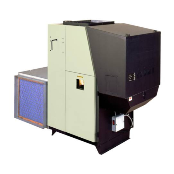
The harman PF 100 Pellet Pro Furnace
"Ce manuel est disponible en Français sur demande"
r19
SAFETY NOTICE
PlEASE rEAd ThIS ENTIrE mANuAl bEFOrE YOu INSTAll ANd uSE YOur NEw FurNACE. FAIlurE TO
FOllOw INSTruCTIONS mAY rESulT IN PrOPErTY dAmAgE, bOdIlY INjurY, Or EvEN dEATh.
FOr uSE IN ThE u.S. ANd CANAdA. SuITAblE FOr INSTAllATION IN mObIlE hOmES (SEE Pg. 17).
IF ThIS PEllET FurNACE IS NOT PrOPErlY INSTAllEd, A hOuSE FIrE mAY rESulT. FOr YOur SAFETY,
FOllOw INSTAllATION dIrECTIONS.
CONTACT lOCAl buIldINg Or FIrE OFFICIAlS AbOuT rESTrICTIONS ANd INSTAllATION INSPECTION
rEQuIrEmENTS IN YOur ArEA.
CONTACT YOur lOCAl AuThOrITY (SuCh AS muNICIPAl buIldINg dEPArTmENT, FIrE dEPArTmENT, FIrE
PrEvENTION burEAu, ETC.) TO dETErmINE ThE NEEd FOr A PErmIT.
CETTE guIdE d'uTIlISATION EST dISPONIblE EN FrANCAIS. ChEz vOTrE CONCESSIONNAIrE dE hArmAN.
SAvE ThESE INSTruCTIONS.
Item # 3-90-08101
Advertisement
Table of Contents

Related Manuals for Harman PF100


Summary of Contents for Harman PF100
- Page 1 CONTACT YOur lOCAl AuThOrITY (SuCh AS muNICIPAl buIldINg dEPArTmENT, FIrE dEPArTmENT, FIrE PrEvENTION burEAu, ETC.) TO dETErmINE ThE NEEd FOr A PErmIT. CETTE guIdE d’uTIlISATION EST dISPONIblE EN FrANCAIS. ChEz vOTrE CONCESSIONNAIrE dE hArmAN. SAvE ThESE INSTruCTIONS. Item # 3-90-08101...
- Page 2 Parts locator Fan Control Hopper Lid Latches Vent Pipe Hopper Combustion Blower cover Heat Exchanger Shaker Handle Combustion Blower 3 Speed Switch Control Cover Outer Door Latches Outer Door Viewing Glass Filter Box...
-
Page 3: Table Of Contents
SAvE ThESE INSTruCTIONS Hearth & Home Technologies, Inc. 352 Mountain House Road Halifax, PA 17032 Appliance Certification. model: Pellet Furnace - PF100 Test lab: Omni-Test Laboratories, Inc. report #: 135-S-02-2 Type: Pellet Fueled Central/Supplementary For Residential Use Note: This appliance is also approved for Standard(s): CAN/CSA B366.1-M91, UL 391,... -
Page 4: Assembly
Assembly Filter box (Cold Air return) Top (same as bottom) Solid Side Panel Switch Blower access Panel Filter Frame Panel Blower access Panel Cover Bottom (same as top) Fig. 3 Assembling Filter box Tek screw from outside Solid Side Panel The cold air return filter box can be assembled with the filter frame on either side or the back, provided there is access to the combustion blower and flue area. - Page 5 Assembly Assembling Filter box, Cont’d Filter Frame Panel 3. Place the filter frame panel inside the bottom and Filter opening must be up inside the solid panel corner. See Fig. 6 for corner detail. Make sure that the filter opening is up.See Fig.
- Page 6 Assembly Assembling Filter box, Cont’d 5. Place the top on the filter box as shown in figure 8. At this time all Tek screws can be inserted around the filter box. Note: Except for the (6) screws that attach the blower access panel in place.
-
Page 7: Blower Assembly
Assembly blower Assembly Install the blower mounting brackets on the blower as shown in Fig. 11. 1. Install ( 4) Tek screws on each side where shown in Fig. 11. Start with the two center screws. NOTE: There are two small holes in the discharge end of the blower that match the two center holes on the small angle of the blower bracket. - Page 8 Assembly Firebrick Firebrick installation-required The firebrick is shipped in the ash pan. It will need to be placed on the brick shelf as shown in Fig. 15. It can be installed with either face to the fire. Hold the brick longways and slide it down into the slot on the shelf.
-
Page 9: Venting
Installation design The first thing needed is deciding where and how the furnace will be installed. Things that need to be taken into consideration are Venting, Supply and Return Ducting, Electrical, and Condensation Drainage (if A/C is installed). Don’t forget access to the furnace for service. When the return air inlet position is known, the filter box and distribution blower can be installed. - Page 10 venting Fig. 18 NOTE: use only 4” diameter “Pl” venting system. be sure to inspect and clean exhaust venting system frequently. 1” INSTAllATION IS TO bE PErFOrmEd bY A QuAlIFIEd INSTAllEr. 4” Type “L” dO NOT INSTAll A FluE dAmPEr IN ThE or “PL”...
- Page 11 venting venting Configuration graph Fig. 19 To reduce probability of reverse drafting during Hearth & Home Technologies strongly recommends a power failure, hearth & home Technologies the use of outside air for all pellet furnace strongly recommends: applications. •Installing the pellet vent with a minimum vertical Per national building codes, consideration must be rise of five feet.
- Page 12 venting I. The clearance to service regulator vent outlet must be Requirements for Terminating the Venting a minimum of 6 feet. WARNING: Venting terminals must not be recessed J. The clearance to a non-mechanical air supply inlet into a wall or siding. to the building or the combustion air inlet to any other NOTE: Only PL vent pipe wall pass-throughs and fire appliance must be a minimum of 48”.
-
Page 13: Clearances To Combustibles
venting and Clearances Clearances to combustibles If installing the furnace in a room separated from the remaining living spaces, the minimum size of the room must be no smaller than 8’ x 8’. See Fig. 21. The reason for this is heat build-up and required space for service and normal operation.This is the minimum size of the room even if it is built of non-combustible material. - Page 14 venting and Installation The shaded area is where the clearance for the PL vent pipe must be maintained at 3”. After the venting leaves the shaded area it may be installed as per the vent manufacturer instructions. (Only listed 4” pellet vent wall pass-throughs and fire stops may be used.) See Fig.
-
Page 15: Installation
Installation Outside Air The use of outside air is optional. Connecting to outside air may be required by local codes, and is strongly recommended. To install outside air, use 2¾” I.D. metal flex pipe, part # 2-00-08544 (12’6”length) or part #2-00-08545 (25’ length). There is a break-away hole on the rear panel which must be removed before connecting the flex pipe. - Page 16 Installation wall Control wiring The Wall Control sends and receives information from the control board through a 4 wire Datacom cable. There is a 100’ length of this cable supplied with the furnace. 100’ lengths of this cable can also be ordered separately, part #3-20-02583. Alternately, any Datacom cable -CAT3- 2 twisted pair 24ga solid wire can be acquired at a local electrical supply house.
-
Page 17: Mobile Home Installation
1. The furnace must be hooked up to an outside air source.(see page 15) 2. The furnace must be secured or bolted to the floor of the mobile home. Use lag bolts through the PF100 provided holes (see below). EXISTINg 3. The furnace must be... - Page 18 Installing duct Adding Air Conditioning to the pellet furnace. recommendations for Supply Air and return Air duct sizing. An easy rule of thumb for A/C CFM blower size The speed or velocity of air moving through duct is, .75 to 1 CFM for each square foot of conditioned systems increases as the duct decreases in size with space.
- Page 19 Installation FAN/hIgh lImIT CONTrOl Installation & Set-up High limit fan control 1. The Fan Control must be placed in the discharge plenum approximately 11 inches above the discharge opening of the furnace, as close to center as possible. Note: The best place is on the same side as the ash door because of ease of access.
- Page 20 Installation Installing Electrical Power: To install power to the furnace first remove the cover on the circuit breaker junction box shown. Inside you will find the main terminal block.(See wiring diagram on page 36 for location of main terminal block and proper power connections).
-
Page 21: Operation
Operation Fan Control Hopper Lid Latches Vent Pipe Combustion Hopper Blower Cover Heat Exchanger Combustion Cleaning Handle Blower 3 Speed Switch Control Cover Outer Door Latches Outer Door Fig. 40 Filter Box Viewing Glass The Control The control can be covered as shown above, or uncovered as shown at left. - Page 22 Operation Power Light Feed adjuster Indicates power to the Sets the maximum feed control, and is also rate used during “Test” to Test check the Low Fuel Runs all motors ** at full Sensor operation. speed for one minute t o c h e c k o p e r a t i o n . Status Light After one minute the Will be lit in either...
- Page 23 Operation wall Control The wall control acts like a thermostat, a thermister in the wall control is sending temperature information back to the micro processor on the furnace. This information is used to determine the need to increase or decrease Temperature Dial the size of the fire according to the temperature de- mand.
- Page 24 Operation Starting A Fire Automatically ImPOrTANT: be sure there is no fuel or other combustibles in the ash pan prior to lighting. 1. Turn mode Selector to “OFF”. This resets the control in addition to turning it off. 2. Fill hopper with pellets. Fig.
- Page 25 Operation 4. If starting after an empty hopper, turn Feed Adjuster to “TEST” (for one 60 second cycle). This will charge pellets into the auger tube and also allow you to check the motors for operation. NOTE: The auger motor will not operate with the furnace door open.
- Page 26 This is the Control setting that will allow the Wall naphtha, engine oil, or other inappropriate Control to function. materials in the PF100. Store pellets in the manufacturer’s wrapping until needed to prevent pellets from absorbing moisture. do not store fuel within the appliance...
- Page 27 Operation lighting A Fire manually Lighting the fire manually will not be necessary unless the igniter system fails. Follow steps 1 through 5 of the instructions for automatic lighting. Fig. 55 6. Flip the Igniter Switch down into the “MANUAL-LIGHT” position. See Fig. 55. 7.
-
Page 28: Shut Down Procedure
Operation Shut down Procedure: The proper way to shut down the furnace is to turn the mode selector to “OFF”. The control will decrease the feed rate to cool the fire. Once the ESP cools enough, the feeder will stop running. In order to ensure removal of smoke and gases from the remaining fuel in the burn pot, the combustion blower will operate until the ESP cools to a safe... -
Page 29: Maintenance
maintenance burnpot cleaning: The burnpot should be cleaned no less than once a week. For best operation the burnpot should be cleaned every time the hopper is filled with pellets. The fire does not have to be out to scrape the burnpot although it is recomended the furnace be on minimum burn at the time of cleaning. -
Page 30: Ash Removal
maintenance Ash removal It is recommended to remove the ashes when the furnace is not in operation. This lessens the chances of coming in contact with hot surfaces. Ashes can be removed while in operation but, extra care must be taken. - Page 31 maintenance Cleaning the accordion heat exchanger/firebox: This cleaning should be done monthly, or after each ton of pellets used. The frequency of this cleaning will be directly related to the quality and upper baffle the quantity of the pellets being used. Keep in mind that the cleaner the heat exchanger surface is kept, the higher the heat transfer efficiency will be.
- Page 32 maintenance Combustion blower Cleaning Remove the combustion blower heat shield.There are two latches that hold the shield in place . See Fig. 69 Flip the latches up and pull the shield away from the furnace. It can not be fully removed, it can only be latch moved down over the wire until it hangs on the junction box.
- Page 33 maintenance Clean the flue outlet throat ( this is the hole that goes up into the flue pipe). See Fig. 72. Note: The ESP sensing tip extends into this same area. CArE muST bE TAKEN NOT TO dAmAgE ThE ESP durINg ClEANINg. Bending of the Sealing overlap ESP will make it difficult to remove if it should become necessary.
-
Page 34: Troubleshooting
Troubleshooting FEEdEr dOES NOT FEEd SmOKE IS vISIblE COmINg OuT OF vENT 1. No pellets in hopper. 1. Air-fuel ratio is too rich. 2. Firebox draft may be too low for low draft pressure A. Feed rate too high switch in feeder circuit to operate. Check for closed B. -
Page 35: Specifications
Specifications 49.652 11.00 20.065 65.525 25.966 15.883 9.743 25.250 49.652 22.035 20.065... -
Page 36: Wiring Diagram
wiring diagram PLUG WHITE VIOLET VIOLET WHITE SKY BLUE WHITE WHITE VIOLET PURPLE BLUE BLACK VIOLET 120 VAC INPUT YELLOW BLUE BLUE BLACK BLACK 10 AMP CIRCUIT BREAKER MAIN JUNCTION BOX... -
Page 37: Parts Information
Parts Identification... - Page 38 door Parts...
-
Page 39: Service Parts
PF100 Pellet Service Parts beginning manufacturing date: N/A Pellet Furnace Ending manufacturing date: Active 1-70-08100 IMPORTANT: THIS IS DATED INFORMATION. When requesting service or replacement parts for Stocked your appliance please provide model number and serial number. All parts listed in this manual may be ordered from an authorized dealer. - Page 40 PF100 Pellet Service Parts beginning manufacturing date: N/A Ending manufacturing date: Active #11 Feeder Assembly Pre SN 004350582 or 008350087 11.2 11.3 11.1 11.4 11.5 11.6 11.12 11.11 11.7 11.8 11.9 11.10 IMPORTANT: THIS IS DATED INFORMATION. When requesting service or replacement Stocked parts for your appliance please provide model number and serial number.
- Page 41 PF100 Pellet Service Parts beginning manufacturing date: N/A Ending manufacturing date: Active #12 Post Feeder Assembly SN #004350582 or 008350087 12.1 12.12 12.15 12.16 12.14 12.2 12.13 12.11 12.3 12.10 12.9 12.4 12.5 12.8 12.7 12.6 IMPORTANT: THIS IS DATED INFORMATION. When requesting service or replacement Stocked parts for your appliance please provide model number and serial number.
- Page 42 PF100 Pellet Service Parts beginning manufacturing date: N/A Ending manufacturing date: Active IMPORTANT: THIS IS DATED INFORMATION. When requesting service or replacement Stocked parts for your appliance please provide model number and serial number. All parts listed in this manual may be ordered from an authorized dealer.
- Page 43 PF100 Pellet Service Parts beginning manufacturing date: N/A Ending manufacturing date: Active IMPORTANT: THIS IS DATED INFORMATION. When requesting service or replacement Stocked parts for your appliance please provide model number and serial number. All parts listed in this manual may be ordered from an authorized dealer.
-
Page 44: Testing Label
SampleTesting label PF 100 A Harman PF 100 may be connected to an existing furnace or heat pump Une Harman PF 100 duct system. 352 mountain house road, halifax, PA 17032... -
Page 45: Warranty
HARMAN™ CENTRAL HEATINg PRODUCTS LIMITED WARRANTY Hearth & Home Technologies Inc., on behalf of its Harman™ brand (”HHT”), extends the following warranty for all Harman™ furnace and boiler products (“Products”) that are purchased from an HHT authorized dealer. Warranty Coverage: Subject to the conditions, exclusions and limitations set forth below, HHT warrants to the original... - Page 46 back-up Power Supply This wiring schematic shows the optional use of a standard UPS (uninterrupted power supply). In the event of a power failure, this will provide power to the combustion blower to remove smoke and other exhaust gases from the furnace. WHITE WHITE BLUE...
-
Page 47: Fuel Specifications
Fuel Specifications Fuel and Fuel Storage (38mm) Pellet fuel quality can fluctuate from manufacturer to • Pellet length can vary from lot to lot from the manufacturer, and even from bag to bag. same manufacturer Hearth & Home Technologies recommends using Performance only fuel that is certified by the Pellet Fuels Institute •...
Need help?
Do you have a question about the PF100 and is the answer not in the manual?
Questions and answers